- We offer co-operation on replacement of old installed equipment on equipment at substations with new equipment produced at your factory. We have a large database of documentation for old, end-of-life equipment, and we will adapt your products to replace the old.

- Design of substation equipment in accordance with the technical specifications.

- Design documentation for the manufacture of electrical equipment.

- 3-D models, product drawings, BOM.

- Preparation of technical documentation for participation in tenders.

- Preparation of preliminary standards for material consumption for cost calculation..

- Consulting on projects.

..since August 1998

Proekt-Energo

Area of activity:

- Design of low-voltage, middle-voltage and high-voltage electrical equipment of substations for voltages of 0.4 - 220 kV.
- Development of working documentation in accordance with the technological capabilities of the plant.
- Preparation of preliminary technical documentation for participation in tenders for the supply of equipment.
- Consultations on project approvals.
- Supporting the production of equipment at the plant.

Specialization:

- Switchgear for indoor and outdoor installation for voltages of 6, 10, 20, 35 kV.
- Air-insulated secondary switchgears AIS for voltages 6, 10 kV.
- Complete transformer substations CTS for voltage 10 - 220 kV.
- Disconnectors for voltage 0.4 ... 220 kV.
- Drive to disconnectors.
- Replacement of withdrawable elements and switches in existing switchgear (Retrofit).
- Low-voltage switchgears for voltage 0.4 kV.
- DC 600V switchgears RU-600.

K-301 “Volga” Medium-Voltage Switchgear 35 kV

KRU K-301 “Volga” is a 35 kV modular medium-voltage switchgear line designed for transmission and industrial power systems where reliable clearing of short-circuit currents up to 31.5 kA is required in networks with isolated or compensated neutral. The panels receive and distribute three-phase 50 Hz power, forming modular line-ups in indoor substations, factory-built modular substations, and plant main substations. Each cubicle is a welded/riveted frame made of 2 mm galvanized sheet, optionally Cr III passivated - corrosion resistance > 1000 h in salt-spray testing (ISO 9227). External panels are coated with polyester powder, RAL 7035.

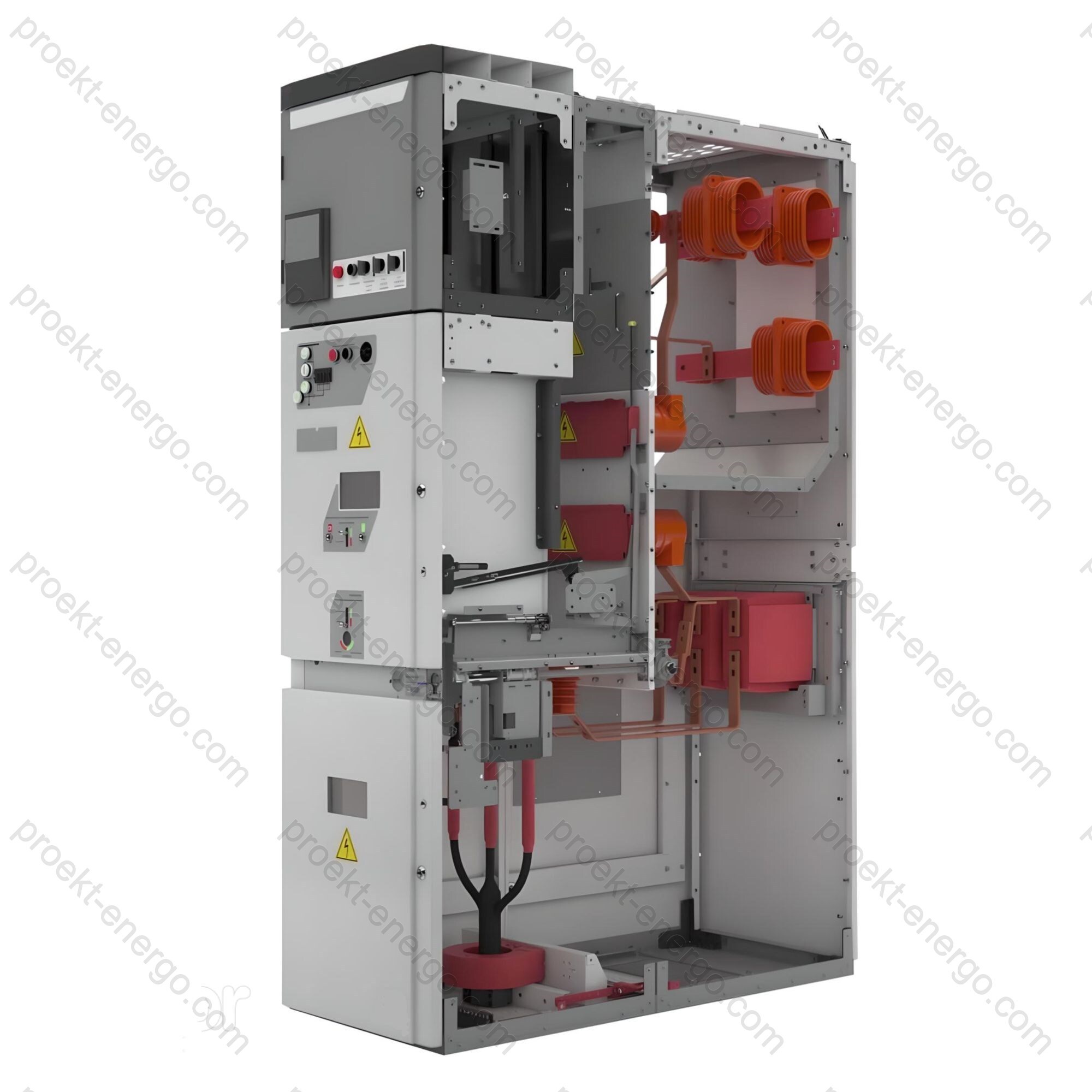
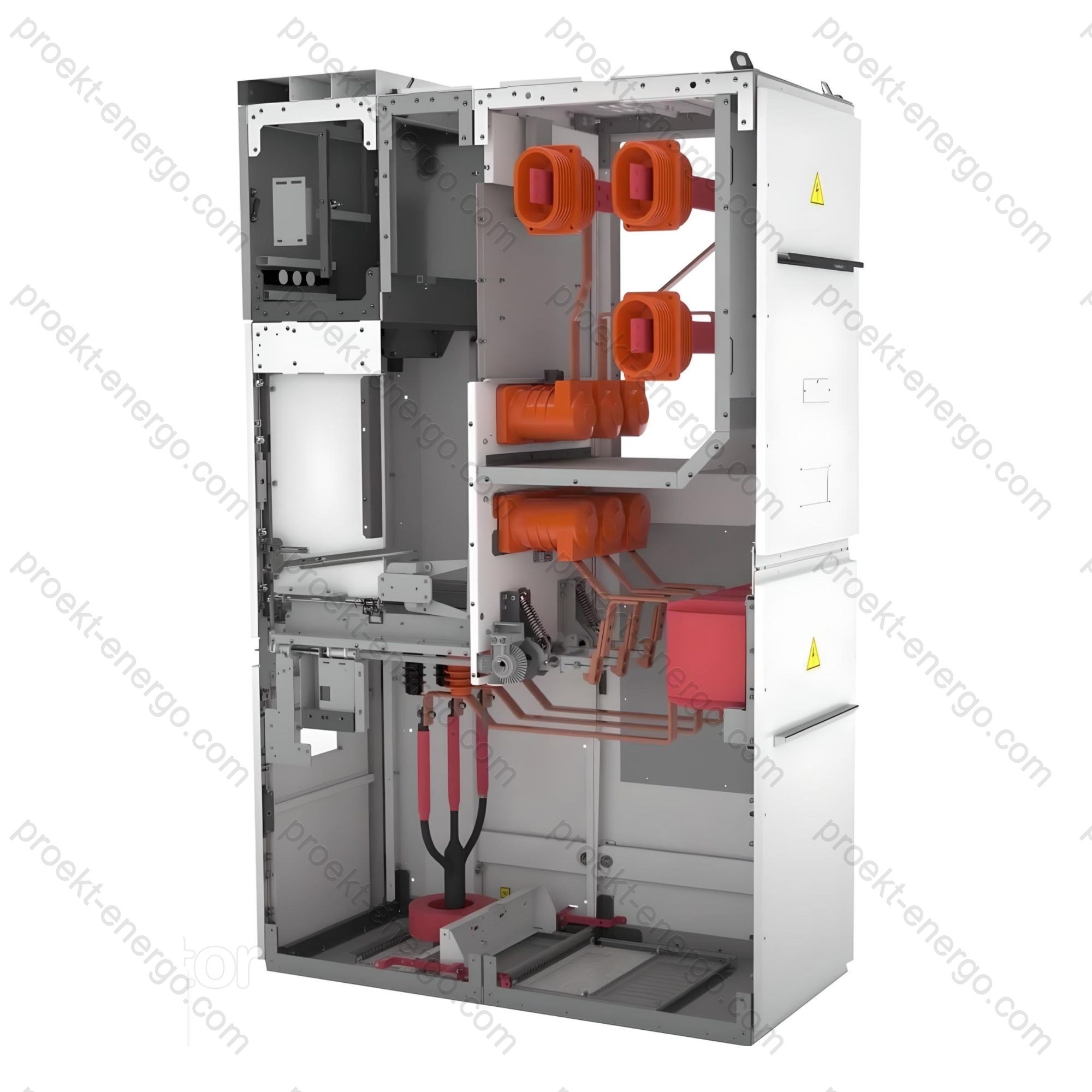
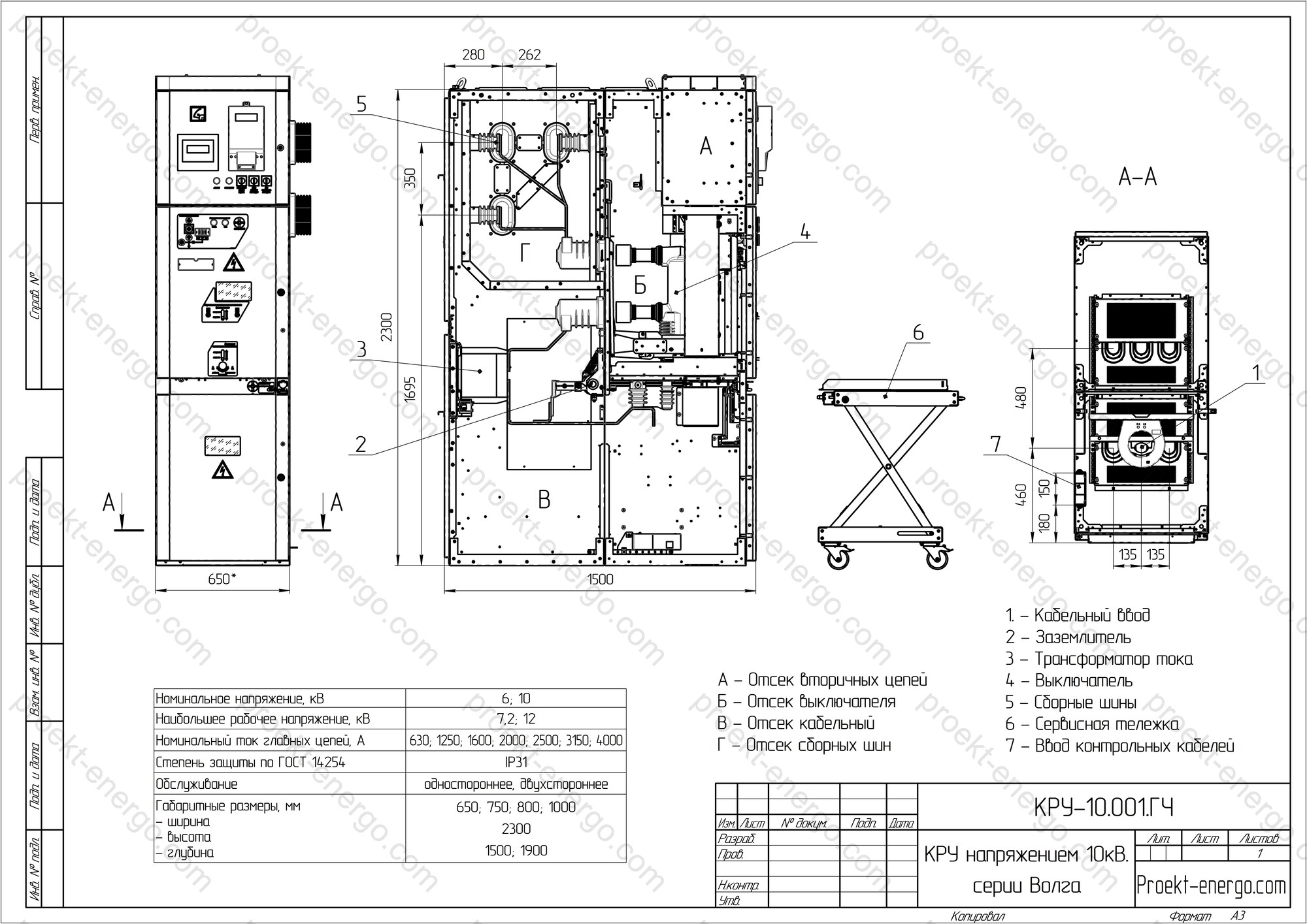
The enclosure is divided into four isolated zones: busbar, withdrawable circuit-breaker, cable, and relay/control compartments. Each has its own pressure-relief duct with rupture membranes that vent hot gases strictly upwards, protecting personnel at the front. Internal-arc tests per IEC 62271-200 confirmed class IAC AFL 31.5 kA 1 s; external surface temperatures did not exceed 240 °C and doors remained operable. A seismic option is available certified for 8-degree MSK-64 with reinforced bracing and M20 anchor bolts.

The withdrawable unit is equipped with a 40.5 kV vacuum circuit-breaker (M2/E2/C2) from VD4 (ABB), SION (Siemens), Susol (LS) or equivalents. The cassette travels on dual channel rails; the “in-service → test” operation is completed in 90 s with a single handle. A motor operator (option) enables remote racking and switching via SCADA. The six-pole primary contact set uses bushing insulators with copper studs; transition resistance ≤ 20 µΩ verified by type test reports.

The cable compartment accommodates a 40 kA earthing switch, 0.2S-class current transformers, ZnO surge arresters, and VDS capacitive voltage indicators for non-contact voltage presence. Busbars are copper: 1 x 10 x 80 mm (up to 1600 A) or a stack 2 x 10 x 80 mm (2000-2500 A); joints use mushroom-head bolts and damping pads to reduce short-circuit forces and magnetostriction. All secondary wiring runs in shielded ducts; a mounting frame is prepared for IEC 61850 Ed.2 IEDs and an LC-to-SC 24-fiber optical patch panel.

Standards and references:

  • IEC 62271-200 (up to 52 kV) - IAC AFL 31.5 kA 1 s;
  • IEC 62271-100 - 40.5 kV circuit-breakers, class M2/E2/C2;
  • IEC 62271-102 - earthing switches, mechanical endurance 5000 cycles;
  • IEC 60071-1 - LI 170 kV / SI 95 kV;
  • EN/IEC 60721-3-3 - environmental conditions (indoor); IEC 60529 - IP 31 (option IP 41/IP 54).

Scope of application

K-301 “Volga” is installed in permanent and fast-deployable indoor MV switchgear:

  • 110/35/6 kV transmission and distribution substations in the oil & gas sector;
  • plant main substations: metallurgy, cement, and chemical industries;
  • auxiliary switchboards of TPP and GTES units rated 100-300 MW;
  • factory-built modular substations for renewable generation and data centers.

Technical data

Rated voltage, kV 35
Maximum system voltage, kV 42
Rated current of main circuits, A 630; 1250; 1600; 2000; 2500
Rated busbar current, A 1600; 2000; 2500
Thermal withstand (3 s), kA 20; 25; 31.5
Dynamic withstand (1 s), kA 51; 64; 81
Maintenance access two-sided
Insulation level (IEC 60071-1) standard
Environmental conditions EN/IEC 60721-3-3 (indoor)
Degree of protection (IP) IP 31 (IEC 60529)
Overall dimensions, mm
- width
- depth
- height

1200
2250
2500

Documentation for manufacturing K-301 “Volga”

Tender package. Single-line diagrams, data sheets, and technical description.

Manufacturing drawings and 3-D models. Layouts, BOMs, secondary schematics, cable schedules.

Enclosures and mechanisms are produced at certified facilities; assembly and routine tests are performed at your site.

Adaptation to existing equipment. We develop drop-in panels to interface with legacy busbars.

Why work with us

Lower staffing costs. Documentation is clear to mid-level engineers.

Series launch without prototypes. We use proven modules and standard solutions.

24/7 support. Assistance with assembly, commissioning, and digital integration.

Contact: inbox@proekt-energo.com

PDF - K-301 “Volga” Technical Brochure

PDF: technical data K-301 “Volga”

K-63 Medium-Voltage Switchgear 6(10) kV

The K-63 series is a family of 6(10) kV medium-voltage switchgear for receiving, distributing, and switching three-phase power at 50/60 Hz in systems with an isolated neutral or a neutral earthed via an arc-suppression reactor / resistor. The metal-clad concept with a withdrawable circuit-breaker, rigid compartmentalization, and comprehensive interlocking enables safe operation and confines fault effects within a single compartment.

KRU K-63 is designed for all types of power plants, utility and plant substations, oil & gas facilities, and urban/rural distribution networks. Panels can be supplied to extend existing switchgear line-ups and connect via transition panels or directly. Installation in factory-built modular buildings (incl. series K-59) and brownfield retrofit of existing switchgear are supported with minimal civil works.

The cabinet body is welded from sheet steel with RAL 7032 powder coating. Each panel comprises a base enclosure, a withdrawable unit (truck), and a relay/control compartment. The primary section may include current/voltage transformers, primary conductors, and separable contacts (providing the disconnector function on the withdrawable unit). The relay compartment houses P&C IEDs, control, metering, annunciation, and terminal blocks for convenient commissioning and service.

A key layout feature of K-63 is the busbars arranged at the bottom with the feeder (line) compartment above. This simplifies work with instrument transformers, earthing switches, and power cables, and provides easy access for busbar terminations. Rear covers of the line and busbar compartments are removable and fitted with viewing windows; through-access to section busbars is available when required. Secondary wiring in MV compartments is protected by covers; cables in the truck compartment are routed along the sidewalls.

The front door of the truck compartment has a viewing window and can remain closed in all truck positions (in-service / test / intermediate). The door carries voltage-presence indicators (feeder / busbar), a mimic showing truck position, and breaker/earthing-switch status to help prevent human error. Shifting the truck to the maintenance position is performed after racking to test; two-sided maintenance access is available.

Standards compliance.

  • IEC 62271-200 - requirements for metal-enclosed MV switchgear; internal-arc classification IAC (as specified);
  • IEC 62271-100 - 12 kV vacuum circuit-breakers; IEC 62271-102 - earthing switches;
  • IEC 60071-1 - insulation coordination (standard insulation level);
  • EN/IEC 60721-3-3 - environmental conditions for indoor installations; IEC 60529 - degree of protection IP31.

Scope of application

K-63 panels are intended for indoor MV switchgear rooms and modular substations in new-build and retrofit projects:

  • utility transmission and distribution substations at 6–10 kV;
  • auxiliary switchgear of TPP/HPP/CCPP units; busbar sectioning;
  • industrial substations (metallurgy, chemicals, pulp & paper, agro-industry);
  • oil & gas infrastructure: CPF/booster stations, well pads, compressor/GPP sites;
  • electrification of utilities, agricultural, logistics, and IT facilities.

Service conditions

  • Climate - EN/IEC 60721-3-3 (indoor, weather-protected); ambient -25...+40 °C (below this range - panel heating required);
  • Altitude up to 1000 m a.s.l. (higher - insulation/thermal derating by calculation);
  • Non-hazardous atmosphere, free of conductive dust;
  • Enclosure degree of protection - IP31; maintenance access - two-sided.

Design features of K-63

  • Bottom busbar arrangement with the line compartment above - convenient for cabling and service;
  • Withdrawable unit with separable contacts; inspection windows and front-panel mimic;
  • Removable rear covers with viewing windows; through-access to section busbars;
  • Protected routing of secondary wiring; cables along the sidewalls of the truck compartment;
  • Mechanical/electrical/key interlocks prevent incorrect operations;
  • Compatibility with modular buildings (incl. K-59); transition options for coupling to existing switchgear.

Configuration and options

  • Vacuum circuit-breaker 12 kV (manufacturer - as specified), CTs/VTs, earthing switch;
  • Functions: incoming, bus-section, outgoing feeders, metering/measurement, VT panel, ATS/AR;
  • Voltage-presence indicators (feeder/busbars), arc-flash protection (on request);
  • P&C IEDs supporting AR/ATS/UFLS, SCADA integration; IEC 61850 if required;
  • Options: enhanced IP, relay-compartment heating, heavy-duty anchors, transition panels for coupling.

Reliability and lifetime

  • Internal-arc effects confined within a single compartment; adjacent panels remain serviceable;
  • M2/E2/C2-class vacuum circuit-breakers - endurance up to 30,000 CO operations;
  • RAL 7032 powder coating; protected secondary routing - durability and EMC robustness;
  • Unified interlocking logic and clear position indication reduce operator error risk.

Technical data

Rated voltage, kV 6; 10
Maximum system voltage, kV 7.2; 12
Rated current of main circuits, A 630; 1250; 1600; 2000; 2500; 3150
Rated busbar current, A 1250; 1600; 2500; 3150
Thermal withstand current (3 s), kA 20; 25; 31.5
Dynamic withstand current (1 s), kA 51; 64; 81
Maintenance access two-sided
Insulation level (IEC 60071-1:2019) standard
Environmental conditions EN/IEC 60721-3-3 (indoor)
Degree of protection (IP) IP31 (IEC 60529)
Overall dimensions, mm
- width
- depth
- height

750; 1125
1400
2300

We offer documentation for manufacturing KRU K-63:

Single-line diagrams, data sheets, technical description, and feasibility inputs.

Manufacturing drawings and 3-D models. Layout/assembly drawings, BOMs, secondary schematics, cable schedules.

Contract manufacturing of subassemblies. We organize enclosure/mechanism production with partners; you perform assembly, wiring, and routine factory tests.

Adaptation and integration. Drop-in panels for interfacing with existing busbars and P&C, expansion of installed switchgear.

Why work with us:

No staff expansion needed. Documentation is tailored to a mid-level engineer.

Series launch without prototypes. Proven modules and standard solutions.

24/7 support. Guidance on assembly, commissioning, and digital integration.

Contact: inbox@proekt-energo.com

PDF - K-63 switchgear Technical Brochure

PDF: technical data K-301 Volga

K-12 (K-XII) Medium-Voltage Switchgear 6(10) kV

KRU K-12 (K-XII) is a complete medium-voltage switchgear system for receiving, distributing, and switching three-phase AC at 50 Hz with rated voltage up to and including 10 kV. The layout is intended for general-purpose distribution switchgear, thermal and hydro power plants, utility substations, and industrial electrical installations.

Environmental conditions comply with EN/IEC 60721-3-3. The equipment is operable at ambient air temperatures down to -25 °C (room heating may be required). The atmosphere must be non-hazardous and non-flammable, free of aggressive gases/vapors that attack metals and insulation, and free of conductive dust.

A typical K-12 panel follows the metal-clad concept with segregated compartments: the base enclosure, a withdrawable unit (truck), a relay/control compartment, and a busbar compartment. For K-12 variants (breaker panels, voltage-transformer panels with fuses, surge-arrester panels, and panels with separable primary contacts) a truck is provided; for other functional panels the truck may be omitted.

The functions of bus and line disconnectors are performed by separable primary contacts: the fixed parts are mounted in the cabinet, the moving parts are on the truck. The truck has three positions: in-service, test (isolated), and maintenance; latching is provided in the in-service and test positions. Transfer to maintenance is performed after racking to test.

The enclosure is a welded sheet-steel structure divided by horizontal and vertical partitions into compartments:

  • truck (withdrawable unit) compartment;
  • upper separable-contact compartment (fixed contacts on post insulators);
  • lower separable-contact compartment (CTs with fixed contacts, earthing switch, zero-sequence CT, cable bar/termination assembly);
  • busbar compartment (busbars on post insulators, separated by a plate with bushing insulators; for double-row line-ups a bus-tie bridge is used).

Protective folding shutters separate the truck from the upper and lower contact compartments; a horizontal shutter is kinematically linked to the leaves and closes/opens automatically as the truck moves. With the truck withdrawn, the shutters can be padlocked. The vertical shutters are split horizontally: with the lower contacts de-energized, only the lower leaves can be opened without touching the upper ones. Pivoting lower edges ensure the required clearances when open.

Earthing switch - moving and fixed contacts with a lever drive; positive latching in the ON/OFF positions and padlocking capability. Interlocks prevent energizing external connections and block truck racking from test to in-service with the earthing switch closed (a mechanical stop tracks the earthing-switch shaft position).

The front door of the truck compartment has a viewing window (per data sheet) and allows truck operations in all fixed positions with the door closed. The façade carries voltage-presence indicators (feeder/busbars) and a mimic diagram showing the truck position (test/in-service), breaker status, and earthing-switch status - helping to prevent operator error.

Standards compliance.

  • IEC 62271-200 - requirements for metal-enclosed MV switchgear; internal-arc classification IAC (as specified);
  • IEC 62271-100 - 12 kV circuit-breakers; IEC 62271-102 - earthing switches;
  • IEC 60071-1 - insulation coordination (standard insulation level);
  • EN/IEC 60721-3-3 - environmental conditions (indoor); IEC 60529 - degree of protection IP31.

Scope of application

K-12 (K-XII) is intended for new and retrofit indoor MV switchgear and factory-built modular substations:

  • auxiliary switchgear of TPP/NPP/CCPP units; sectioning and metering;
  • utility and plant substations at 6-10 kV for industrial facilities;
  • oil & gas power systems, water utilities, and public infrastructure;
  • modernization of existing switchgear retaining interface dimensions and cable routes.

Service conditions

  • Environmental class - EN/IEC 60721-3-3; operating ambient range: -25…+40 °C;
  • Altitude - up to 1000 m a.s.l. (above this - insulation/thermal checks by calculation);
  • Atmosphere - non-hazardous, free of aggressive gases/vapors and conductive dust;
  • Degree of protection - IP31 (higher IP on request).

Design features of K-12 (K-XII)

  • Compartmentalization: truck ⋅ upper/lower separable-contact compartments ⋅ busbars;
  • Separable primary contacts perform bus/line disconnector functions;
  • Folding shutters with mechanical interlock and padlock; split vertical leaves;
  • Bus-tie bridge for coupling sections in double-row arrangements;
  • Mimic and indication on the façade: truck position, breaker, earthing switch, voltage presence.

Reliability and safety

  • Internal-arc effects confined within a compartment by shutters and partitions;
  • Interlocks: no racking with earthing switch closed; positive latching of ES and truck positions;
  • Removable covers and viewing windows for safe inspections and service;
  • Shielded routing of secondary wiring - improved EMC robustness.

Technical data

Rated voltage, kV 6; 10
Maximum system voltage, kV 7.2; 12
Rated current of main circuits, A 630; 1250; 1600; 2000; 2500; 3150
Rated busbar current, A 1250; 1600; 2500; 3150
Thermal withstand current (3 s), kA 20; 25; 31.5
Dynamic withstand current (1 s), kA 51; 64; 81
Maintenance access two-sided
Insulation level (IEC 60071-1:2019) standard
Environmental conditions EN/IEC 60721-3-3 (indoor)
Degree of protection IP31 (IEC 60529)
Overall dimensions, mm
- width
- depth
- height

900; 1100
1660
2370

We offer documentation for manufacturing KRU K-12:

Tender package. Single-line diagrams, data sheets, and technical description for bids and feasibility assessment.

Manufacturing drawings and 3-D models. Layout/assembly drawings, BOMs, secondary schematics, and cable schedules - tailored to your production.

Contract manufacturing of subassemblies. We arrange fabrication of enclosures and mechanisms with partners; you perform assembly, wiring, and routine factory tests.

Adaptation and integration. Drop-in panels for interfacing with existing busbars/secondary circuits and third-party equipment.

Why work with us:

No staff expansion needed. Documentation is designed for a mid-level engineer.

Fast series launch. Standardized modules and proven solutions reduce schedule and risk.

Technical support. Guidance on assembly, commissioning, and digital integration of P&C/SCADA.

For more details on KRU K-12 contact: inbox@proekt-energo.com

PDF - Download KRU K-12 technical information

PDF: technical data KRU K-12 (K-XII)

KRU “Omega” Medium-Voltage Switchgear 6(10) kV

The “Omega” series of 6/10 kV medium-voltage switchgear is designed for receiving, distributing, and switching three-phase AC at 50/60 Hz in systems with an isolated neutral or a neutral earthed via an arc-suppression reactor / resistor. The solution targets indoor distribution switchgear of substations and industrial facilities where safety, modularity, and ease of maintenance are required.

The enclosure is a modular steel construction made of galvanized sheet with powder-coated front parts (high corrosion resistance). A distinctive layout feature is the busbar system in the upper rear section, a withdrawable unit in the middle, and the cable/bus compartments beneath it or beneath the busbar compartment. This architecture increases usable feeder volume and ensures full front access, enabling one-sided operation and maintenance when required.

For arc-fault safety the design uses metal-clad compartmentalization with solid metallic and insulating barriers. Typical compartments include: a relay/low-voltage compartment, a withdrawable circuit-breaker compartment, a busbar compartment, and a cable compartment. On request, the truck can be motorized for remote test ↔ in-service movement, and the earthing switch can be equipped with an electric actuator (ON/OFF). Optional features include video surveillance (breaker / earthing-switch compartments) with display at the control desk, contact-temperature monitoring, and a front mimic panel.

Scope of application

“Omega” switchgear is used at generation, transmission, and distribution facilities as well as by industrial consumers:

  • Indoor MV switchgear of package substations (KTP) and urban 6-10 kV distribution points;
  • Industrial plant substations; auxiliary switchgear of power plants (TPP/HPP/CCPP);
  • Utilities and infrastructure: water utilities, pump stations, heat centers, data centers;
  • Factory-built modular substations and retrofit of existing switchgear line-ups;
  • Back-to-back (double-row) line-ups - interconnection by bus bridges or cables (on request).

Service conditions

  • Environmental conditions - EN/IEC 60721-3-3 (indoor); operating ambient -25…+40 °C;
  • Altitude - up to 1000 m a.s.l. (above this - insulation/thermal verification by calculation);
  • Non-hazardous atmosphere, free of conductive dust and aggressive vapors/gases;
  • Degree of protection - IP31 (IEC 60529);
  • Maintenance access - one-sided or two-sided, depending on the switchgear layout.

Design features

  • Full compartmentalization: LV/relay compartment ⋅ withdrawable unit ⋅ busbar ⋅ cable compartment;
  • Withdrawable vacuum circuit-breaker with optional motorized racking (test/in-service);
  • Motor drive for the earthing switch (ON/OFF), interlocks per safety logic;
  • Options: cameras in breaker/earthing-switch compartments, contact-temperature monitoring, front mimic panel;
  • Bus bridges / cable interconnections for double-row line-ups; common earthing bar per IEC 61936-1;
  • Multi-point door latching, keyed locks; directed pressure-relief upwards.

Standards compliance

  • IEC 62271-200 - metal-enclosed / metal-clad MV switchgear, LSC/PM; internal-arc classification IAC (as specified);
  • IEC 62271-100 - 12 kV vacuum circuit-breakers; IEC 62271-102 - earthing switches;
  • IEC 60071-1:2019 - insulation coordination (standard insulation level);
  • EN/IEC 60721-3-3 - environmental conditions (indoor); IEC 60529 - IP degrees of protection;
  • IEC 61000-6-2 / 61000-6-4 - EMC (industrial immunity/emissions).

Reliability and lifetime

  • Internal-arc effects confined to a single compartment, minimizing impact on adjacent panels;
  • Mechanical and electrical interlocks - prevention of incorrect operations;
  • Metal cable ducts for secondary circuits - EMC robustness and serviceability;
  • Powder-coated galvanized steel - high corrosion resistance and durability.

Technical data

Rated voltage, kV 6; 10
Maximum system voltage, kV 7.2; 12
Rated current of main circuits, A 630; 1250; 1600; 2000; 2500; 3150
Rated busbar current, A 1250; 1600; 2500; 3150
Thermal withstand current (3 s), kA 20; 25; 31.5
Dynamic withstand current (1 s), kA 51; 64; 81
Maintenance access one-sided; two-sided
Insulation level (IEC 60071-1:2019) standard
Environmental conditions EN/IEC 60721-3-3 (indoor)
Degree of protection IP31 (IEC 60529)
Overall dimensions, mm
- width
- depth
- height

650; 800; 1000
1500; 1900
2360

We offer documentation for manufacturing KRU “Omega”:

Tender package. Single-line diagrams, data sheets, and technical description for bids and feasibility assessment.

Manufacturing drawings and 3-D models. Layouts, BOMs, secondary schematics, cable schedules.

Contract manufacturing of subassemblies. We place assemblies and parts with partner shops under quality control.

Adaptation to existing equipment. We design drop-in panels to interface with legacy busbars.

Why work with us

No staff expansion. Documentation is clear to a mid-level engineer.

No prototypes required. Proven modules and standard solutions shorten lead time.

24/7 support. Consulting on assembly, commissioning, and digital integration.

Questions? Write to inbox@proekt-energo.com

PDF - Technical information, KRU “Omega” 10 kV

PDF: technical data - KRU “Omega” 10 kV

KRU "Volga" Medium-Voltage Switchgear 6(10) kV

KRU "Volga" is intended for receiving, distributing, and switching three-phase power at 6 and 10 kV, 50/60 Hz, in systems with an isolated neutral or a neutral grounded via an arc-suppression reactor/resistor. The standardized bays are designed for indoor substations and industrial power systems where operating safety, serviceability, and layout flexibility are critical.

The base design is a modular enclosure made of high-rigidity galvanized steel with powder-coated facade panels. The interior is divided into independent compartments by solid steel and insulating partitions to confine any internal arc to a single volume. Busbars are arranged in the upper rear area (for the top-busbar option), the withdrawable unit (truck) is in the middle, and the cable/busbar compartment is below it or directly beneath the busbar section. This architecture increases usable termination space and enables single-sided routine operation.

Applications cover both primary and secondary distribution: KRU "Volga" is used by generating and grid companies, on industrial substations, and at municipal/utility and process-infrastructure sites. In two-row switchrooms (fronts facing), section busbars are linked by bus-duct bridges or cable jumpers (supplied on request). All current-carrying parts and metallic elements are bonded to earth per applicable standards, ensuring safe working conditions.

Service conditions for indoor installation:

  • altitude up to 1000 m a.s.l. (above this-apply insulation/cooling recalculation);
  • ambient temperature from -25 °C to +40 °C (room heating recommended at sub-zero temperatures);
  • relative humidity up to 80 % at +15 °C; environmental conditions per EN/IEC 60721-3-3;
  • non-hazardous area, free of conductive dust and aggressive gases/vapors.

To enhance safety under arc faults, the cubicle is divided into four functional zones: cable compartment, withdrawable-unit (CB) compartment, busbar compartment, and protection/LV compartment. Each MV compartment has its own directed pressure-relief flaps.

Cable compartment. Provides space for current transformers, surge arresters, support insulators with capacitive dividers, a space heater, and, if required, a stationary or truck-mounted VT. CT secondary leads are routed directly into the LV compartment via flexible tails, avoiding service work on secondaries inside MV sections. Cable terminations are positioned at a height of at least 700 mm above floor level. Possible connections: up to three 3-core cables to 240 mm² each or up to six 1-core cables to 630 mm². A door interlock prevents opening until the earthing switch is in the Closed (earthed) position.

Withdrawable-unit (truck) compartment. Equipped with a front door featuring multi-point latching and an arc-resistant design that prevents hot-gas ejection towards the operator. Pressure is relieved via top flaps. Six bushing insulators with fixed rod contacts are mounted on the rear; a fast spring-operated earthing switch is installed externally. The shutter mechanism blocks access to fixed contacts when the truck is in the test position; shutters can be padlocked. Interlocks prevent opening the door until the truck is in test and the earthing switch is set to "Earthed." LED lighting is provided for service convenience.

Busbar compartment. Available with top or bottom busbars. With top busbars, overpressure is vented through the top flaps; with bottom busbars-via arc chutes along the lineup edges. For selective compartmentalization, busbars pass through bushing insulators (except the bottom-busbar variant). Conductors are oxygen-free copper with edge radiusing (target radius ~5 mm) to reduce field stress. Typical cross-sections: up to 1600 A - 1×10×80 mm; 2500 A - 2×10×80 mm; 3150 A - 3×10×80 mm; 4000 A - 3×10×100 mm. Controlled fastener types and torques ensure stable contact pressure in normal and fault conditions.

Protection/LV compartment. Dimensions support modern digital IEDs, metering/measurement devices, interface modules, and fiber-optic arc sensors. The door carries control keys, pilot lights, and indicators; terminal strips and auxiliaries are arranged at the bottom. Devices mount on DIN rails; an optional swing frame can be used. Anti-condensation heating with thermostat is provided; harnesses are routed in protected inter-bay raceways.

For higher automation and remote control (per spec), options include a motorized CB truck (test/service transfer), motor drive for the earthing switch (close/open), local cameras in the CB and ES compartments with feeds to the control room, contact-temperature monitoring, and a front-panel mimic diagram.

Standards compliance

  • IEC 62271-1 - Common specifications for MV switchgear and controlgear;
  • IEC 62271-200 - AC metal-enclosed/metal-clad switchgear up to and including 52 kV (LSC/PM, IAC classification);
  • IEC 62271-100 - AC circuit-breakers; IEC 62271-102 - Earthing switches; IEC 62271-103 - Switches/load-break;
  • IEC 61869-2/-3 - Instrument transformers (CTs/VTs);
  • IEC 60529 - Degrees of protection (IP code);
  • IEC 61000-6-2 / 61000-6-4 - EMC (industrial immunity/emissions);
  • IEC 60068-2 series - Environmental/mechanical tests (as applicable).

Reliability and lifetime

  • Compartmental arc containment with directed pressure relief - adjacent bays remain serviceable;
  • Mechanical/electromagnetic interlocks prevent unsafe operations;
  • Metallic raceways for secondary circuits - EMC robustness and service access;
  • Galvanized steel with powder coating - long-term corrosion resistance.

Technical data

Rated voltage, kV 6; 10
Highest system voltage, kV 7.2; 12
Rated current of main circuits, A 630; 1250; 1600; 2000; 2500; 3150; 4000
Rated busbar current, A 1250; 1600; 2500; 3150; 4000
Short-time withstand current (3 s), kA 20; 25; 31.5
Peak (dynamic) withstand current (1 s), kA 51; 64; 81
Service access single-sided; double-sided
Insulation level (IEC 60071-1:2019) normal
Environmental classification (EN/IEC 60721-3-3) EN/IEC 60721-3-3
Degree of protection (IEC 60529) IP31
Overall dimensions, mm
- width
- depth
- height

650; 750; 800; 1000
1500; 1900
2300

We offer documentation for manufacturing KRU "Volga":

Tender package. Single-line diagrams, questionnaires, and technical descriptions for procurement and feasibility review.

Working drawings & 3-D models. Layout/assembly drawings, BOM, secondary schematics, and cable schedules tailored to your production.

Contract manufacturing of assemblies. We arrange fabrication of enclosures and mechanisms with partners; you handle assembly, installation, and routine tests.

Adaptation & integration. Equivalent bays for interfacing with existing busbars/secondary circuits and third-party equipment.

Benefits of working with us:

No extra staff. Documentation is optimized for a mid-level engineer.

Fast series launch. Standardized modules and typical solutions reduce schedule and risk.

Technical support. Consulting on assembly, commissioning, and digital integration of protection/SCADA.

For additional information on KRU "Volga", contact: inbox@proekt-energo.com

PDF - Download KRU "Volga" technical information

pdf

  • Operating manual for equipment

    Operating manual for equipment

  • Technical specifications

    Technical specifications

  • 3-D models

    3-D models

  • Operating manual for equipment

    Operating manual for equipment

  • Equipment drawings

    Equipment drawings

  • Equipment drawings

    Equipment drawings

  • 3-D models

    3-D models

  • Regulatory and technical documentation

    Regulatory and technical documentation

  • Equipment drawings

    Equipment drawings

  • 3-D models

    3-D models

  • Technical specifications

    Technical specifications

  • Operating manual for equipment

    Operating manual for equipment

  • Regulatory and technical documentation

    Regulatory and technical documentation

  • Technical specifications

    Technical specifications

  • Regulatory and technical documentation

    Regulatory and technical documentation

Demo

FEEDBACK FORM