RG-110 Horizontal-rotary disconnector, rated voltage 110 kV
The RG-110 series of horizontal-rotary disconnectors is designed for safe making and breaking of de-energized sections of substation circuits and distribution facilities of the 110 kV class, as well as for reliable earthing of disconnected sections by means of built-in earthing switches integrated with the apparatus. In 110 kV air-insulated switchyards (AIS), the RG-110 performs operational isolating to provide a visible break, busbar sectionalizing, feeder transfer/backup, and supports switching for maintenance, testing and insulation tests. The disconnector is intended for long-term outdoor service and integrates into typical 110/35/10 kV substation schemes: single and one-and-a-half busbar systems, 110 kV line bays, power-transformer bays, and AIS yards.
Purpose and application
RG-110 apparatus is applied at both new-build and retrofit substations, in distribution points and grid nodes, at industrial sites and infrastructure facilities (rail traction, metallurgy, petrochemicals). Core functions: creating a visible isolation gap for safe personnel access; no-load switching of individual busbar sections and feeders; scheme reconfiguration for contingency transfer; applying and removing earthing on equipment terminals for work. When equipped with a motor drive, and in accordance with the manufacturer’s instructions, switching of power-transformer magnetizing current and 110 kV line/cable charging currents is permitted, which simplifies commissioning, outages for maintenance and routine operations.
Disconnectors are available in single-, two- and three-pole versions. The pole coupled to the operating mechanism is the leading pole. Configurations include a “blade-on-post” single-side-break arrangement with horizontal rotation of the current-carrying blade by 90° (main circuit) and 90°/180° (earthing switch). The design ensures stable contact pressure, low contact resistance and high short-circuit withstand appropriate for the 110 kV class. In retrofit projects, RG-110 is suitable as a replacement for obsolete two-column series while preserving mounting interfaces and inter-phase spacing, and for expanding busbar sections by modular addition of new poles.
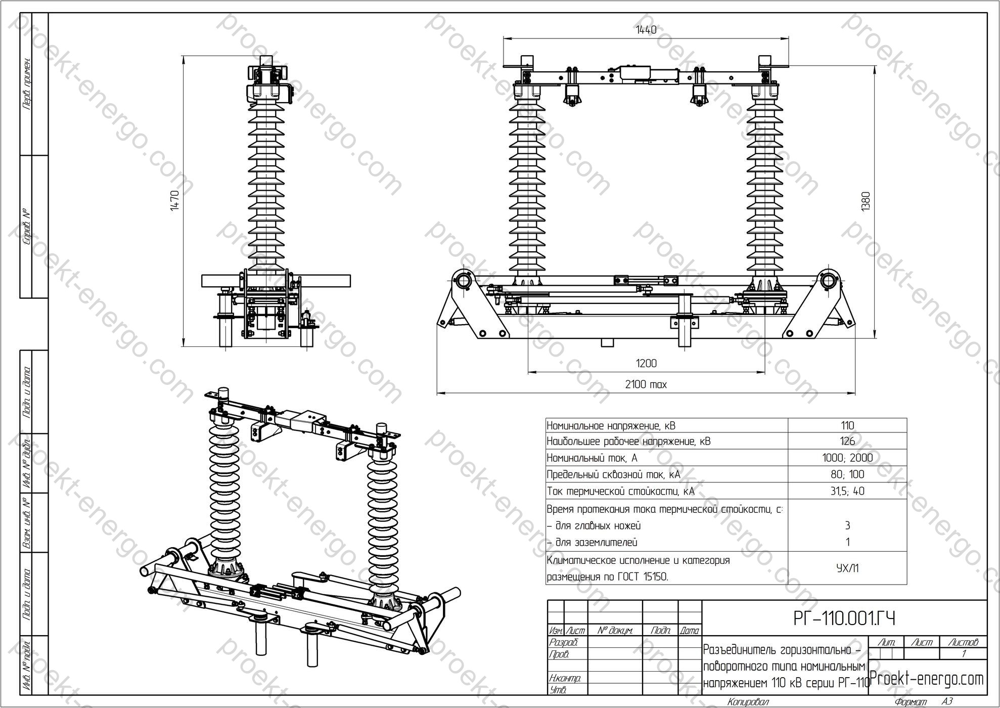
Technical data
| Rated voltage, kV | 110 |
| Maximum system voltage, kV | 126 |
| Rated current, A | 1000; 2000; 3150 |
| Rated peak withstand current, kA | 80; 100; 125 |
| Rated short-time withstand current, kA | 31.5; 40; 50 |
| Duration of short-time current withstand, s – main blades – earthing switches |
3 1 |
| Creepage distance of external insulation, cm, not less than | 200 |
| Conductor tension in the horizontal plane incl. wind, N, not less than | 800; 1000 |
| Minimum clearances from live parts to various elements of the disconnector (in air), mm: – from live parts to grounded structures; – between live parts of different phases; – between the open contacts of one pole |
– 900 – 1000 – 900 |
Service conditions
RG-110 disconnectors are manufactured for environmental conditions classified per IEC 60721-3-4 (stationary use at non-weather-protected locations). Operating temperatures from -60 °C to +40 °C; altitude up to 1000 m. Allowable wind speed in service: up to 40 m/s with no icing and up to 15 m/s with ice thickness up to 20 mm. Mean annual relative humidity up to 80 % at +15 °C. Maximum wind pressure: 700 Pa without icing and 140 Pa with ice cover. For areas with heavy pollution and salt fog, versions with increased creepage distance and shielding are available, including polymer insulators with enhanced hydrophobicity. Dielectric performance is in accordance with IEC 62271-1 and insulation coordination per IEC 60071-1/-2 for the 110 kV class; typical creepage distances are selected to IEC 60815 by pollution severity class I–IV.
Degrees of protection for drive enclosures and terminal boxes are selected to project requirements per IEC 60529; typically not lower than IP54 for outdoor drive cabinets. Resistance to mechanical environmental effects can be provided to the IEC 60068-2 series (vibration, shock) for sites with increased vibration and seismicity (as specified by the project).
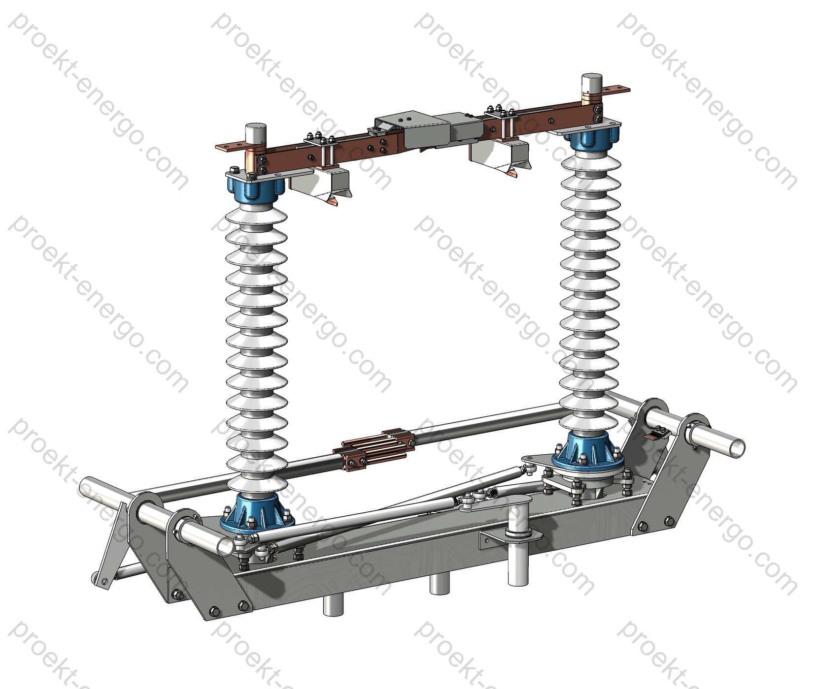
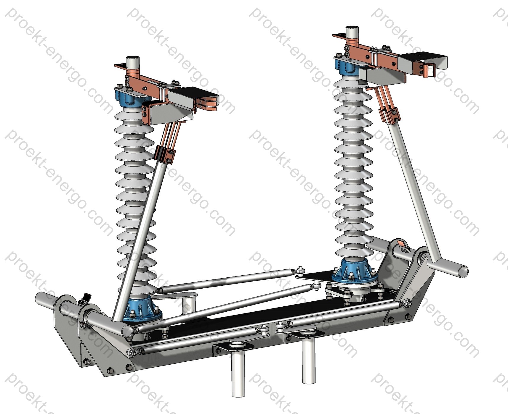
Layout and design solutions
Each RG-110 pole comprises a base frame, a support column with a post insulator, a rotating shaft with linkage, the main current-carrying blade, fixed and moving contacts, and an earthing-switch assembly (if fitted). Maintenance-free bearing supports and sealed joints are used in moving parts, eliminating routine lubrication over the service life. Current-carrying contact surfaces are copper with galvanic plating (tin/silver); floating contact packs with silver plating provide constant contact pressure and low resistance over many operating cycles. Shielding parts and corona rings minimize local field intensification at sharp edges of live parts.
The kinematic scheme ensures precise pole synchronization, adequate contact overlap in the closed position and a guaranteed visible break when open. Operating torque from the manual or motor drive is transmitted to the leading pole via links and cardan joints; follower poles are coupled by rods, preventing inadvertent closing under wind or electrodynamic forces. Structural rigidity of the frame is achieved with welded profiles hot-dip or thermodiffusion galvanized; aluminum covers and shields resist corrosion and icing. All bolted joints are secured with locknuts/washers; torque-check marks are provided.
The insulating part can be supplied on porcelain or polymer support/bushing insulators. For harsh environments, extended insulators with increased creepage and anti-icing hoods are available. Connection of both flexible and rigid busbars is provided; on request, transition pads, adapters for tubular bus and flange clamps for various busbar stacks are supplied. Mechanical endurance is at least 10 000 “close-open” cycles, matching long service in 110 kV distribution networks with typical operation counts.
| Key design assemblies | Execution features |
| Main-circuit contact system | Silver/tin coatings, floating contact packs, stabilized pressure, low contact resistance, corona rings. |
| Support/bushing insulators | Porcelain or polymer; creepage length per pollution severity; anti-icing hoods. |
| Operating linkage | Maintenance-free bearings, sealed joints, temperature-compensation features, position interlocks. |
| Corrosion protection | Hot-dip/thermodiffusion galvanizing of steel parts; aluminum shields; protected fasteners. |
Safety and interlocks
The interlocking system prevents mal-operations and ensures personnel safety. Mechanical interlock blocks closing of the earthing switch when the main blades are closed, and conversely blocks closing of the main circuit when the earthing switch is closed. End-position latches are provided, with the ability to apply padlocks (lockout/tagout, LOTO) on the manual-drive handle and on pole levers. Electrical interlock and limit switches (e.g., KSAM-type or equivalent) provide discrete signals “CLOSED/OPEN” for the main circuit and “EARTHED”; groups of auxiliary contacts can be installed for SCADA/DCS and protection & control (PAC). Mechanical position indicators are visible from the operating level.
With proper adjustment of the linkage, self-movement under wind loads or short-circuit forces is excluded. Procedures for checks, contact-overlap adjustment, limit-switch setting and operating-force verification are described in the service documentation and performed during commissioning.
Variants and options
The RG-110 product line provides a wide range of options to adapt to site and client requirements. Typical options include:
| Option | Description |
| Drive type | Manual PRG-6 (outdoor) with electromagnetic interlock; motor PD-14 with local/remote control. |
| Earthing switches | Without earthing switch / with one or two earthing switches (on the moving- or fixed-contact side). |
| Insulation | Porcelain (pollution classes I–II) or polymer (up to class IV); extended creepage for marine/industrial areas. |
| Pole arrangement | Three-pole with inter-pole rods; mirror execution; left/right drive; variable inter-phase spacing. |
| Additional items | Corona rings, shielding parts, anti-icing hoods, LOTO guards and tags, service platforms, stands/bases. |
| Signalling & interfaces | Auxiliary-contact groups for SCADA/DCS, limit switches, terminal boxes IP54 and above, cable glands per project. |
Drives and control
Operation of main blades and earthing switches is performed by manual PRG-6 drives (outdoor) or by PD-14 motor drives. The manual drive provides fixed end positions with padlocking in the end positions, a folding handle and standard electromagnetic interlock; local control cabinets can be used to install control and signalling devices. The PD-14 motor drive provides remote control and is equipped with a motor-gear unit, limit switches and local controls; AC/DC control circuits are provided as per project. In both cases the linkage geometry and rod lengths are set on site to ensure synchronized pole movement and the required contact overlap.
Standards compliance
RG-110 disconnectors are designed and manufactured in line with current standards and normative documents for medium-voltage switching equipment, including (up to six key documents applicable to this product):
- IEC 62271-102: AC disconnectors and earthing switches - electrical/mechanical requirements, tests and safety.
- IEC 62271-1: Common specifications for switchgear and controlgear.
- IEC 60071-1/-2: Insulation coordination - definitions, principles and application guides.
- IEC 60529: Degrees of protection (IP code) for enclosures.
- IEC 60815 (series): Selection and dimensioning of high-voltage insulators for polluted conditions.
- IEC 60721-3-4: Classification of environmental conditions - stationary use at non-weather-protected locations.
Engagement with contractors and cooperation
We invite cooperation with manufacturing sites, engineering companies, installation and commissioning contractors, as well as investors interested in deploying and localizing production of RG-110 disconnectors. Support is provided at all stages: from pre-design studies and data-sheet definition to serial launch and warranty/post-warranty service. Flexible models are available: supply of a complete design package for in-house manufacturing, contract manufacturing of assemblies and parts at partner plants, or delivery of kits for large-unit assembly at the customer’s site. For bus-duct and steelwork manufacturers, 3D models and interface dimensions are available for AIS layout coordination.
Deliverables and digital models
The documentation package is tailored to the specific project and typically includes: specifications, assembly drawings, parts lists and linkage drawings, schematic diagrams and drive connection diagrams, bill of materials (auxiliary switches, limit switches, interlocks), product passport/manual, test programs and procedures, commissioning logs, as well as 3D models of assemblies and the complete unit in exchange formats (Parasolid/X_T, STEP) and native formats (SolidWorks), DWG/DXF drawings for integration into structural/electrical working documentation. On request we provide models for control-cable routing, interlock schemes and torque-tightening charts.
Our advantages
– No need to maintain a large team of highly qualified engineering staff - you receive a complete documentation set that can be used by a mid-level engineer.
– No need to build experimental prototypes - our experience allows serial production launch straight away.
– Working to our documentation, your specialists receive full guidance on all manufacturing nuances of RG-110 disconnectors.
Partnership for manufacturers and contractors
– Steelwork manufacturers - we provide frame and support assemblies, overall and interface dimensions for AIS portals; we agree protective coatings and galvanizing requirements.
– Bus-duct manufacturers - we provide adapters and interface dimensions, recommendations on tolerances and drilling templates.
– Commissioning companies - on-site test instructions, signalling/interlock verification procedures, typical SCADA/DCS integration schemes.
– Investors and EPC - effort and cost assessment, supply plan for large-unit assemblies, localization schedules.
For additional information on RG-110 disconnectors please contact: inbox@proekt-energo.com
PDF - Download technical information for RG-110 disconnectors
Documents


