K-3 (K-III) Outdoor Metal-Enclosed Medium-Voltage Switchgear
The KRUN K-3 (K-III) outdoor metal-enclosed medium-voltage switchgear is intended for the reception and distribution of three-phase AC power at 50 Hz with rated voltages of 6–10 kV. It is applied in auxiliary power systems of power plants, at substation switchyards of utility grids and industrial facilities, for agricultural power supply, as well as in the oil & gas production sector.
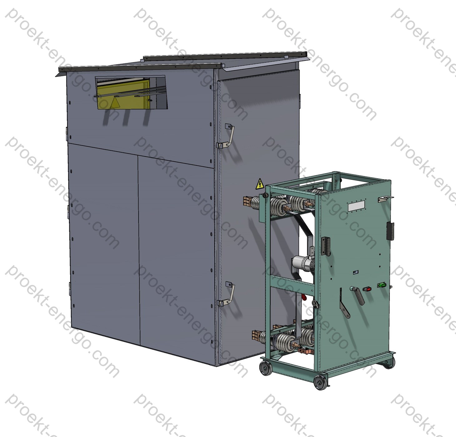
KRUN K-3 (K-III) is assembled from individual cubicles. Enclosures are welded from bent sheet steel. Each cubicle is divided by solid metal partitions into compartments: medium-voltage, control, and busbar. Adjacent cubicles have openings for busbar connections, bolting holes for forming a single block, and openings for routing control cables. Depending on function, cubicles are configured as follows:
- VCB cubicle - vacuum circuit-breaker feeder (cable / busbar / overhead line entry);
- SST cubicle - station service transformer;
- BS CB - bus-section circuit-breaker cubicle;
- VT cubicle - voltage transformer;
- BS DS - bus-section disconnector cubicle.
The quantity and types of cubicles are selected according to the project.
A vacuum circuit-breaker cubicle can include a line disconnector, a busbar disconnector, a vacuum circuit breaker, current transformers, and-if required-surge arresters and a core-balance (zero-sequence) CT.
A voltage-transformer cubicle includes a VT with a busbar disconnector and fuses; it also accommodates busbar earthing switches. Surge arresters may be installed on the main busbars.
A station service transformer cubicle houses the power transformer (specified in the data sheet, typically 25 or 40 kVA), together with a busbar disconnector and fuses. Depending on the single-line diagram, an overhead line entry of the incoming breaker can be routed into the SST cubicle.
Purpose and application
KRUN K-3 (K-III) is designed for building reliable 6–10 kV medium-voltage networks at outdoor substations and as part of compact transformer substations. It provides line in/out, bus/feeder sectioning, metering, measurement, protection, and automation for networks with isolated neutral or with neutral earthed through an arc-suppression reactor. Typical applications include:
- Auxiliary power switchgear of power plants; outdoor switchyards (35–220 kV) with 6–10 kV MV sections.
- Industrial sites: mining & processing, metallurgical and chemical plants, refineries, oil & gas production pads, transport and port infrastructure.
- Agricultural consumers, farms, grain elevators, and distribution points on long 6–10 kV OH/UG feeders, including feeder sectioning and automatic transfer/reclosing.
- Temporary and permanent power for construction bases, quarry complexes, and fields with mobile logistics.
Functionally, KRUN K-3 (K-III) receives power from power transformers and distributes it to outgoing feeders, sections buses/feeders, connects measuring transformers and station-service transformers, and integrates with AMR/AMI systems and telecontrol subsystems. The enclosure design and built-in equipment allow both compact distribution points and extended bus sections with various connection schemes-from simple incomers to complex nodes with bus-section circuit breakers, bypass links, and bus bridges.


Technical data
| Rated voltage, kV | 6; 10 |
| Maximum operating voltage, kV | 7.2; 12 |
| Rated current (main circuits), A | 630; 1000; 1600 |
| Rated busbar current, A | 630; 1000; 1600 |
| Thermal withstand current 3 s, kA | 20; 25; 31.5 |
| Dynamic (peak) withstand current ~1 s, kA | 51 |
| Environmental category (EN/IEC 60721-3-4) | EN/IEC 60721-3-4 (outdoor) |
| Ingress protection (IEC 60529) | splash-proof IР34 |
| Service corridor | none (front access) |
| Type of line MV terminations | cable, overhead |
| Insulation level (IEC 62271-1/-200) | standard insulation |
| Withdrawable elements | none (fixed-mounted) |
| Overall dimensions, mm - width - depth - height |
1000 1870 2500 |
Service Conditions
Cubicles are intended for outdoor installation and continuous duty under the following normalized environmental factors:
- Environmental category - EN/IEC 60721-3-4 (outdoor). The K-3 series is engineered for moderate climates with exposure to precipitation, dust, and solar radiation. The enclosure includes drip edges and splash protection (IP34) to prevent ingress of rain and melt water.
- Installation altitude - up to 1000 m above sea level without derating; higher-altitude use may require adjusted insulation levels and currents.
- Location category - outdoor; vertical operating position; non-hazardous atmosphere, not saturated with conductive dust or aggressive vapors; no internal condensation provided ventilation and heating requirements are observed.
- Wind and snow loads are considered in foundation/support design and when selecting optional overhead line entries; in areas with deep snow cover, installation on an elevated platform is permissible (plinth/skid height per project).
- Options for seismic reinforcement, enhanced anticorrosion coating, “North” package (thermostated heaters, insulated cable entries, moisture protection of the relay compartment), and “Dust/Desert” package (additional filter inserts, mesh screens on ventilation) - as per data sheet.
For correct operation of protection and switching devices, maintain the specified microclimate in the control/relay compartment: dry, heated volume without condensation. Anti-condensation heaters with thermostat are used (installed in breaker and P&C compartments), and cable glands with seals prevent air/moisture ingress.
Layout and Design
KRUN K-3 (K-III) is a modular assembly in a welded metal enclosure with functional segregation by internal partitions. A typical cubicle comprises the following isolated compartments:
- MV circuit-breaker compartment - vacuum circuit breaker (6/10 kV class), current transformers, optional core-balance CT (ring CT around cables), interlocks, position sensors, and arc-flash detection (project-specific). Compartment lighting and heating are provided; removable panels support inspection of contacts and secondary wiring.
- Disconnector and busbar compartment - line/busbar disconnectors with earthing switches, support/bushing insulators, and busbars. Behind the door there is a protective mesh or dielectric screen with viewing windows for visual position check. Mechanical interlocks prevent incorrect operations between work and earthing blades.
- Incoming/feeder terminations - termination of underground cables or overhead line entry with cross-arm and bushings. Surge arresters may be installed at the incomer/feeder; line CTs and capacitive voltage indicators are available for voltage-absence verification prior to earthing.
- Protection & control (P&C) compartment - microprocessor relays (O/C, TOC, earth-fault, under/over-voltage, autoreclose, ATS as required), RTU/PLC for telecontrol, alarm/measurement devices, AMR/AMI meters (accuracy classes 0.5S–1), DC supplies, and terminal blocks. The fascia provides local breaker controls and PR-10 disconnector drives with status indication and key interlocking.
All compartments are sealed volumes separated by solid metallic/insulating partitions, improving fault containment and preventing transfer of arc products between compartments. Air clearances and creepage distances meet the 6/10/12 kV insulation level. Busbars are copper/aluminum with bolted joints; they are air-insulated for easier inspection and maintenance. Provisions are made for inter-cubicle bus joints, bolted tie bars, and secondary cable trays to simplify installation.
The enclosure provides splash-proof protection to IP34: drip edges exclude direct runoff to door openings; ventilation channels use labyrinth paths and mesh filters. Doors have multi-point locks and provisions for padlocks. A comprehensive interlock system ensures safe access: with the breaker and/or disconnectors closed, access to MV compartments is prevented; earthing switches cannot be closed with work blades closed. A grounding point is provided at the base for connection to the external earthing grid; all metal parts are bonded to the enclosure with flexible braids/star washers for reliable electrical contact.
Connection options support both cable and overhead line in/out. Cable terminations use sealed glands and support insulators; overhead line entries use bushings, cross-arms, and lightning protection as per project. The design allows bus-section nodes with bus links and bus-section devices (breaker/disconnector), as well as placement of a station service transformer (25–40 kVA or as specified) in a dedicated cubicle with fuses and a busbar disconnector.
Safety and Interlocking
- Blocking of disconnector operations with the MV circuit breaker closed (mechanical/electrical interlocks per scheme).
- Blocking between working and earthing blades in both directions; intermediate positions excluded by drive latching and limit switches.
- Access to MV compartments is interlocked with device status; doors open only after de-energizing, opening disconnectors, and closing earthing switches.
- Voltage-absence verification (indicators/capacitive sensors) before earthing; application of portable earthing to designated points.
- Arc-flash protection of breaker/bus compartments (optional): light sensors + high-speed tripping; pressure relief flaps for overpressure venting.
Configurations and Options
- Cubicles: incomers (UG cable/OHL), outgoing feeders, bus-section (breaker/disconnector), busbar incomers/links, VT, SST, combined.
- Switchgear devices: vacuum circuit breakers 6/10 kV (breaking capacity up to 20–31.5 kA), disconnectors with PR-10 drives, earthing switches.
- Instrument transformers: CTs with primary currents 50–1500 A, single-/three-phase VTs.
- Surge arresters on busbars and on incomers/feeders; voltage indicators, viewing windows.
- Protection functions: O/C, TOC, earth-fault, under/over-voltage, autoreclose (AR), automatic transfer (ATS); integration with SCADA and telecontrol (Modbus/IEC 60870-5-104/IEC 61850).
- Environmental packages: “North”, “Dust/Desert”, “Marine” (anticorrosion, sealing, heating), anti-vandal versions, enhanced seismic performance - on request.
Typical Configurations
- Incoming cubicle with vacuum circuit breaker, busbar and line disconnectors, CTs, and surge arresters. Cable/OHL entry - per project.
- Outgoing feeder (cable) with breaker, CTs, core-balance CT (for selective earth-fault), feeder surge arresters, local/remote control.
- Bus-section cubicle with circuit breaker (BS CB) for splitting busbars, AR/ATS per relay logic; or bus-section disconnector (BS DS) for maintenance switching.
- VT cubicle (measurement/metering), SST cubicle (25–40 kVA and above, station service supply), busbar incomers/links for multi-row schemes.
Standards Compliance
- EN/IEC 60721-3-4 - environmental categories for outdoor stationary use (replaces GOST 15150 U1).
- IEC 60529 - degrees of protection (IP); enclosure rating IP34.
- IEC 62271-1 / IEC 62271-200 - AC metal-enclosed MV switchgear and controlgear; insulation/dielectric tests and general requirements.
- IEC 62271-100 / IEC 62271-102 - circuit breakers; disconnectors and earthing switches (as applicable).
- IEC 60068-2 series - environmental/mechanical tests (vibration/shock, etc.).
- Commissioning and acceptance testing per applicable IEC/EN standards, FAT/SAT and customer specifications.
Partnering and OEM Cooperation
We invite manufacturing sites and investors to arrange KRUN K-3 (K-III) production under our documentation. We are open to OEM components from leading brands and local suppliers (cable terminations, surge arresters, protection relays). Partners receive guidance on manufacturability, component selection, shop adaptation, and training for assemblers and commissioning personnel.
Documents
We provide a complete design & manufacturing package: BOMs, assembly drawings, primary and secondary schematics, layout drawings, cable lists and secondary wiring lists. Available formats: 2D (DWG/DXF), 3D (SolidWorks/Parasolid), purchased-parts lists, data sheets, transport/storage/installation/operation manuals. On request - export specifications, recommended spares, FAT/SAT templates, and test sheets aligned with IEC requirements. For sites with existing third-party equipment, we can perform reverse engineering and supply compatible cubicles.
Why work with us
- No need to staff highly specialized engineering teams - you receive a complete documentation set for manufacturing, suitable for engineers of average qualification.
- No need to build pilot prototypes - our experience allows direct launch of serial production.
- Working to our documentation - your team receives guidance on all manufacturing nuances of KRUN K-3 (K-III).
For additional information on KRUN K-3 (K-III), contact: inbox@proekt-energo.com
... and, as is well known, an error made at the design stage turns into 10× cost in manufacturing and 100× in operation...
PDF - Download KRUN K-3 (K-III) technical information.


