RG-150 Center-break horizontal-rotating disconnector rated 150 kV
RG-type disconnectors are designed to isolate and re-energize de-energized sections of an electrical circuit with system voltage up to 150 kV, as well as to ground the isolated sections using earthing switches integrated with the disconnectors.
The disconnectors are available in single-pole, two-pole and three-pole versions. The pole to which the operating mechanism is connected is the driving pole. Operating mechanisms are intended for disconnector operation. Rotation of the operating shafts of the main circuit and the earthing switch is performed manually via PRG-6 mechanisms or by the PD-14 motor-operated drive.
The disconnectors are manufactured for outdoor service, installation category 1, in accordance with EN/IEC 60721-3-4 (non-weather-protected locations). The operating conditions are:
- site altitude up to 1000 m;
- maximum ambient air temperature +40 °C;
- minimum ambient air temperature -60 °C;
- wind speed up to 40 m/s with no icing and up to 15 m/s with an ice deposit up to 20 mm;
- average annual relative humidity 80% at +15 °C;
- maximum wind pressure 700 Pa (equivalent to 34 m/s) with no icing;
- maximum wind pressure 140 Pa (equivalent to 15 m/s) with ice accretion up to 20 mm.
Dielectric withstand of the insulation complies with IEC/EN 62271-1 and IEC/EN 62271-102 for the 150 kV class. External creepage distance of standard disconnectors on porcelain insulators per IEC/EN 60815 is:
- for pollution class I - not less than 270 cm;
- for pollution class II - not less than 340 (390) cm;
- for polymer insulators - not less than 340 (390) cm.
Mechanical endurance of the disconnector - 10,000 operating cycles (open-close).
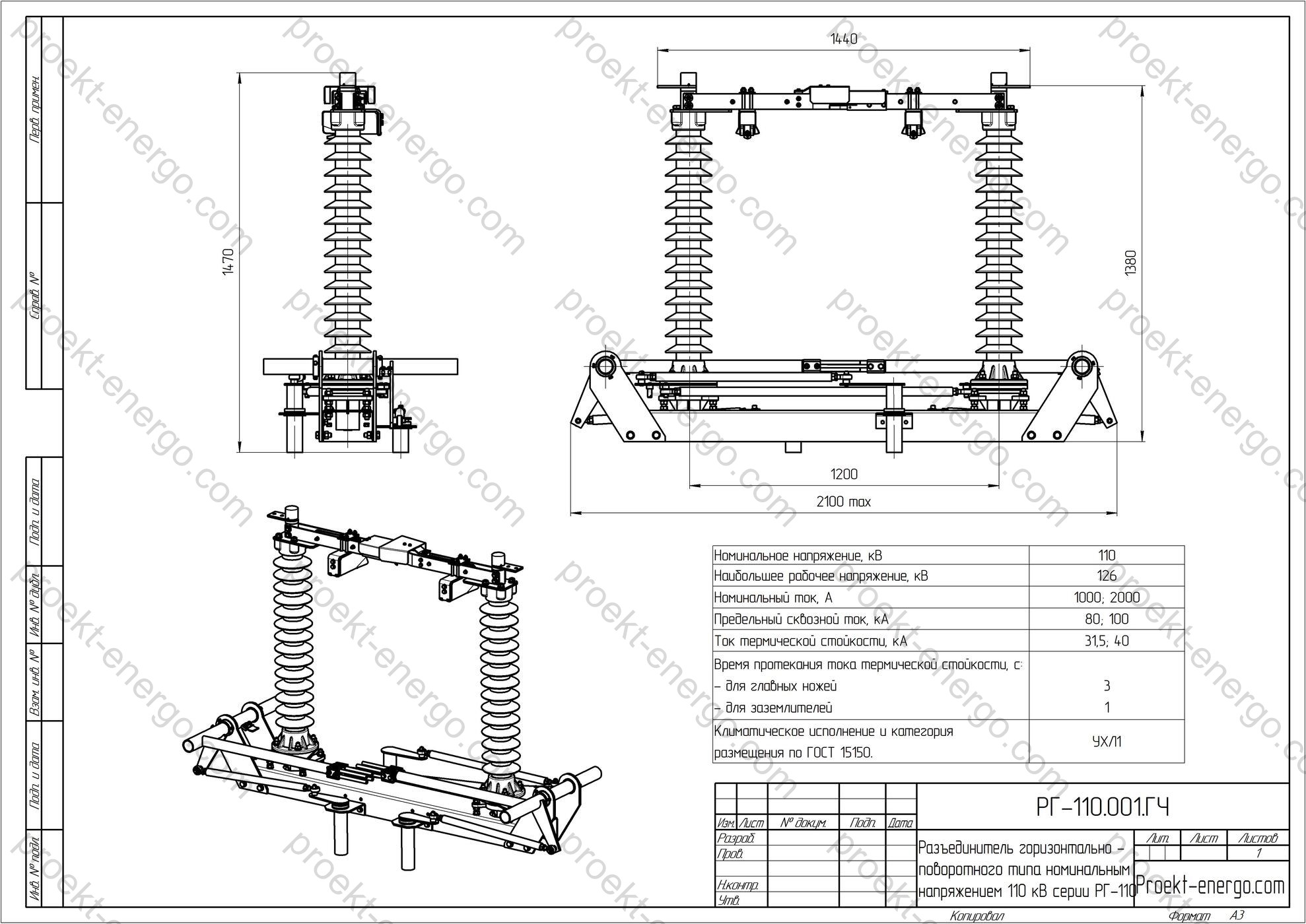
Technical data
| Rated voltage, kV | 150 |
| Highest system voltage, kV | 170 |
| Rated current, A | 1000; 2000 |
| Rated peak withstand current, kA | 100 |
| Rated short-time withstand current, kA | 40 |
| Short-time current duration, s - main blades - earthing switches |
3 1 |
| External creepage distance, cm, not less than | 270 |
| Conductor tension in the horizontal plane considering wind load, N, not less than | 800; 1000 |
| Minimum clearances (in air) from live parts to various elements, mm: - to earthed structures; - between live parts of different phases; - across the open contacts of one pole |
- 1300 - 1400 - 1300 |
Purpose and application
The RG-150 horizontal-rotating (center-break) disconnector provides a visible isolating gap and enables safe maintenance sectioning in AIS switchyards of substations rated 110–150 kV. It is intended for off-load switching of busbar systems and sections, line taps and branches, bypass jumpers, transformer and autotransformer terminals, bus-coupler and bus-section circuits, as well as reactor and compensation device connections. An earthing switch can be integrated to provide operational grounding of isolated sections for work under permit.
Thanks to its modular design, the RG-150 integrates easily into standard AIS schemes: single- and double-bus arrangements, one-and-a-half-breaker, ring, bay, and 110–150 kV overhead line terminals. Availability of manual (PRG-6) or motor-operated (PD-14) drives allows both local operation and integration into SAS/SCADA with remote control and position telemetry.
The disconnector is intended for generating units, transmission and distribution hub substations, AIS nodes of large industrial facilities, RES sites (MV-class wind/solar substations), and urban network supply centers. The design ensures resistance to outdoor climatic impacts, a clearly visible break, and low operating costs thanks to a simple mechanism and easy access for service.
Operating conditions
RG-150 is intended for continuous outdoor service (installation category 1, per EN/IEC 60721-3-4). The design ensures operability at temperatures from -60 °C to +40 °C, under wind loading, rime and icing, dust and precipitation. In marine climates and on industrial sites with chemically active emissions, polymer insulators with increased creepage distance and additional corrosion protection of metal parts are recommended.
Vibration and shock loads from wind gusts and conductor swing are absorbed by the rigid base frame and the articulated drive linkage. Adjustment points are accessible without pole removal; lubrication points are provided with long-life low-temperature greases. On request: space heaters in drive cabinets, wipers for sight-glass indicators, extended humidity range, and anti-icing profiles of current-carrying blades.
For areas with heavy pollution, salt fog, or sand storms, configurations with polymer insulators, hydrophobic coatings, increased creepage distance, and stainless-steel vibration- and corrosion-resistant fasteners are recommended. In lightning-prone regions it is advisable to use equipotential bonding and short flexible shunts with minimal inductance. All cable entries and drive enclosures are gasketed to prevent ingress of moisture and insects.
Design and construction
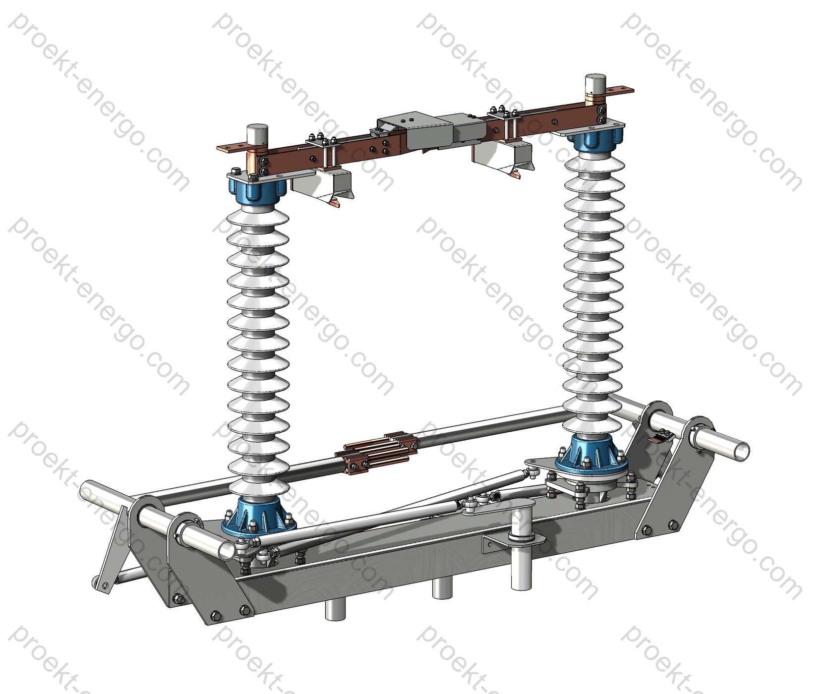
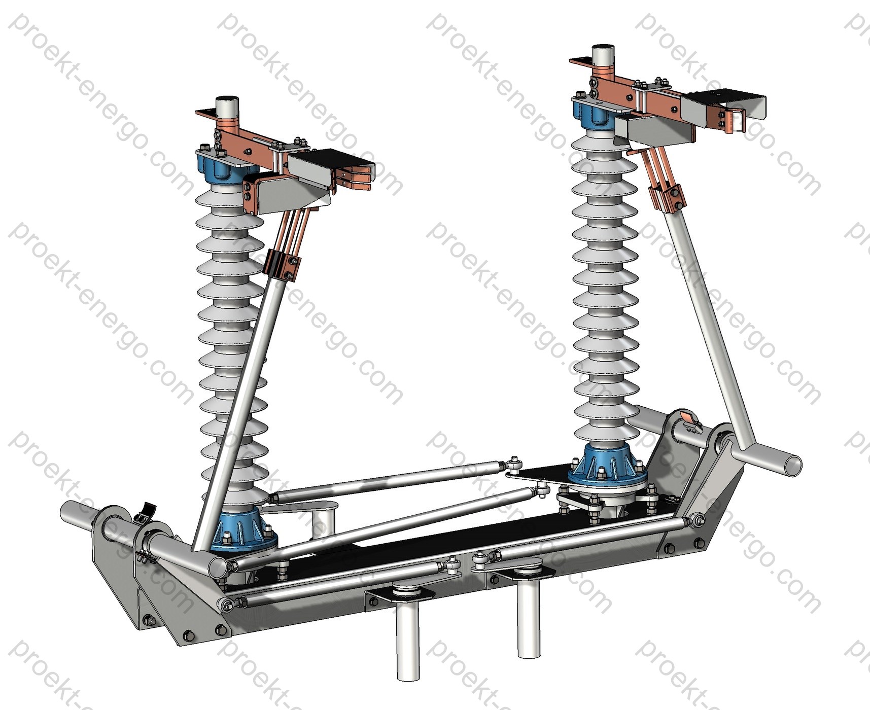
RG-150 is a horizontal-rotating, center-break disconnector. Each pole comprises two pedestal insulators with rotary bearings and an upper current path with a contact blade. In the closed position current flows through the blade’s main contact system; in the open position the blade turns in the horizontal plane, forming a clearly visible isolating distance. The kinematics provide synchronous rotation of the pedestals and high wear resistance over many cycles.
The contact system (tulip-type or box-type, depending on execution) features spring loading and Ag/Sn surface finishes on sliding areas to reduce contact resistance and improve corrosion resistance. Flexible shunts made of multi-strand tinned copper braid with bolted terminations are used between moving members. Current-carrying parts have rounded edges to reduce corona losses.
Support insulators may be porcelain or polymer. Polymer posts offer lower mass and higher resistance to pollution and vibration; porcelain offers high mechanical stiffness and thermal stability. The insulator mounting to the crossarm is adjustable and lockable. Steel structures (base frame, brackets, crossarms) are hot-dip galvanized or protected by multilayer industrial coatings for outdoor service.
An earthing switch combined with the disconnector pole can be installed on the moving-contact side or the fixed-contact side (as per project). Mechanical interlocking prevents its closing when the main pole is closed, and electrical limit switches provide reliable OPEN/CLOSED status signals to the SAS/protection system. For visual control, each pole has a position indicator of the blades with optional illumination for low-light conditions.
Operating mechanisms: PRG-6 hand-operated for local operation and PD-14 motor-operated for remote control and automation. Torque is transmitted via shafts, links and levers with minimal backlash. The design incorporates stops, travel limiters, anti-backdrive locks, and an opening/final-wipe feature to ensure stable contact pressure.
Configurations and options
| Number of poles | Single-pole / Two-pole / Three-pole |
| Drive location | Left / Right / Center (per project) |
| Insulation type | Porcelain / Polymer (increased creepage for polluted areas) |
| Earthing switch | Without / With earthing switch on the moving or fixed contact side |
| Operating mechanisms | PRG-6 (manual) / PD-14 (motor-operated), with limit switches and remote indication |
| Contact system | Tulip/box type, Ag/Sn finishes, tinned Cu flexible shunts |
| Terminals | Flat pads for busbars; clamps for conductors/lugs; adapters for non-standard connectors (on request) |
Control interfaces and interlocking
| Mechanical interlocks | Prevent earthing switch closure with the main pole closed and prevent pole closure with the earthing switch closed |
| Electrical limit switches | Volt-free contacts for SAS/protection circuits, with channel redundancy |
| Position indication | Visual indicators on the pole and a scale on the mechanism; disc indicators on request |
| Lockable devices | Provisions for padlocks; optional key interlocks |
| Remote control | PD-14 motor drive with local/remote selector, heaters, and “ready/fault” contacts |
Safety and interlocking
Personnel safety is ensured by a combination of design and procedural measures. Mechanical interlocks exclude incorrect operations of the main pole and earthing switch. Limit switches and signaling circuits allow unambiguous monitoring of blade positions at the control panel and in the SAS. The visible break removes doubt when issuing work permits and simplifies switching. The mechanisms provide provisions for key/padlock locking to prevent inadvertent operation.
Base frames include bolted points for protective grounding. Phase markings, rotation direction arrows, and “ON/OFF” nameplates are made of UV-resistant materials. Stops and damping elements absorb kinetic energy at end-of-travel, with reserve adjustment to compensate wear. Manufacturing complies with the dielectric, creepage and clearance requirements for this voltage class.
Executions and options
- Insulators: porcelain / polymer (increased creepage for high pollution).
- Earthing switch: on the moving or fixed contact side; double-earthing versions for special schemes.
- Drives: PRG-6 (manual) / PD-14 (motor-operated) with telecontrol, heaters, local/remote selection, ready/fault signals and interlocks.
- Contact system: Ag/Sn finishes; spring-loaded contact force units; anti-icing blade profiles.
- Terminations: flat busbar pads; clamps for conductors and cable lugs; transition adapters.
- Add-ons: key interlocks, disc position indicators, indicator lighting, vibration sensors, additional auxiliary contacts for protection systems.
Compliance with standards
- IEC/EN 62271-102 - AC disconnectors and earthing switches.
- IEC/EN 62271-1 - High-voltage switchgear and controlgear - Common specifications.
- IEC/EN 60815-1/-2/-3 - Selection and dimensioning of insulators for polluted conditions.
- EN/IEC 60721-3-4 - Classification of environmental conditions (outdoor, non-weather-protected locations).
Documents
- Preliminary technical documentation for tender participation for RG-150 manufacturing. We will prepare the information you need to assess the feasibility of producing the product in accordance with tender requirements and data sheets.
- Working drawings, 3-D models and other documentation required to manufacture RG-150 disconnectors at your facility. If you do not plan to fabricate parts in-house, we will help outsource them to qualified suppliers. Final assembly and installation will be performed at your site.
- All documentation can be adapted to project requirements and to your production capabilities, available equipment fleet and routing sheets.
- If your substation uses equipment from another manufacturer, we will prepare documentation for an equivalent unit to unify the installed base and broaden the spare-parts range.
Engaging contractors and partners
We are open to cooperation with mechanical and electrical installation companies, manufacturers of insulators, drives, overhead-line and busbar fittings, as well as with investors interested in launching a disconnector production line. Partnership models include contract manufacturing of assemblies (steelwork, current-carrying parts, shunts), localization of assembly and testing, and full transfer schemes with phased increase of local content.
- For manufacturing contractors: complete design package and specifications, routing sheets, lists of purchased items, incoming inspection and test criteria.
- For installation companies: installation lists, connection diagrams, instructions for linkage/shaft alignment, lubrication charts and maintenance schedules.
- For electrical equipment manufacturers: adaptation of the design to your processes, size ranges matched to your insulators and drives, and unified subassemblies.
- For investors: phased localization business plan, list of critical competencies, capacity ramp-up schedule, CAPEX/OPEX assessment, certification plan.
Why work with us
- No need to maintain a large team of senior engineers - you receive a complete documentation set that can be handled by a mid-level engineer.
- No pilot units required: our experience allows launching serial batches directly to production drawings with shop-floor feedback incorporated.
- Consulting on all aspects of RG-150 manufacturing and adjustment: insulator selection, contact finishes, kinematic tuning, welding and coating qualification, control of creepage distances and air clearances.
For additional information on RG-150 disconnectors, please contact: inbox@proekt-energo.com
PDF - Download technical information for RG-150 disconnectors


