K-104 MV Switchgear – withdrawable unit replacement (retrofit)
Retrofit is an upgrade or partial re-engineering of metal-enclosed switchgear (KRU) and KSO panels by replacing life-expired components with modern devices, preserving capital investments in the existing cubicles.
The core of the upgrade is the replacement of the most wear-prone and critical component - the oil circuit-breaker. It is replaced with vacuum or SF6 circuit-breakers with spring-charged or electromagnetic operating mechanisms; compared with oil CBs, they require less routine maintenance, offer higher endurance and stable short-circuit interruption performance. A comprehensive switchgear modernization is also possible: block replacement of the compartment including the withdrawable unit (drawout truck), shutter mechanism, earthing switch operating mechanism, doors, relay compartment, as well as obsolete indicators and key interlocks.
The reliability of a KRU/KSO panel is directly defined by its switching part. This modernization is a simple and cost-effective solution that reduces failure probability and extends the service life of the switchgear assembly.
Retrofitting existing equipment is more economical than purchasing new gear, simplifies design/installation and shortens power outages; regular overhauls of oil CBs do not ensure reliability, while many cubicle assemblies can be retained.
Purpose and application
The retrofit project for the K-104 withdrawable unit is intended for rapid replacement of obsolete oil circuit-breakers with modern vacuum or SF6 devices while retaining the cubicle frame, bus bridges, cable terminations and secondary circuits. The solution applies to 6–10 kV medium-voltage switchgear at industrial enterprises, power utilities, mining, and infrastructure sites (TP, RP, GPP), as well as facilities with high continuity requirements: data centers, oil & gas, metallurgy, transport, healthcare.
Key objectives solved by the retrofit: improved electrical and fire safety; reduced operating expenses (OPEX); shorter maintenance/repair outages; alignment with current standards for insulation, breaking capacity and interlocking; integration of digital protection relays and breaker condition monitoring; flexible delivery scope - from turnkey execution to a documentation package for in-house manufacturing.
In the standard configuration the new withdrawable unit is fully compatible with mounting points, contact system (tulip/knife contacts), mechanical and electrical interlocks. To accelerate deployment, three baseline approaches are offered: adaptation of the existing withdrawable unit for a new breaker; replacement with a new withdrawable unit assembly; installation of a factory “retrofill”/“hard-bus” module (e.g., One-Fit-class solutions or equivalents) with pre-engineered interfaces and type-tested assemblies.

Technical data
| Parameter | Value / range | Note |
|---|---|---|
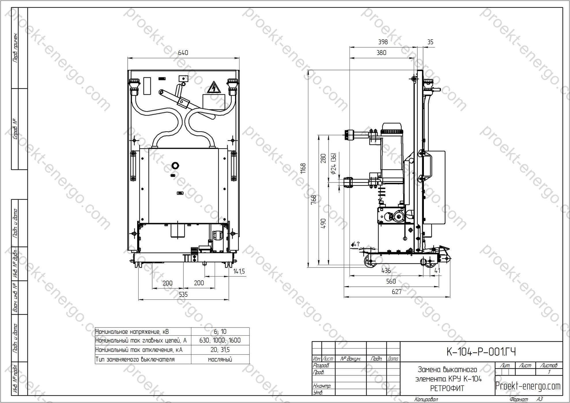
| Rated voltage | 6; 10 kV (50/60 Hz) | Defined by the existing switchgear |
| Rated continuous current | 630–3150 A | Depends on the breaker series and busbar system |
| Rated short-circuit breaking current | 20–31.5 kA (1 s) | Other ratings on request |
| Rated short-time / making withstand | up to 50–80 kA peak | Per selected breaker catalogue |
| Service categories | E1/E2; C1/C2 | For vacuum CBs (endurance / capacitive switching) |
| Degree of enclosure protection | IP3X–IP4X (external surfaces), IP2X (service areas) | Selected per installation location |
| Climatic operating range | from -5 °C to +40 °C (24-h average ≤ +35 °C) | Extended range - on request |
| Installation altitude | ≤ 1000 m a.s.l. | Higher sites require insulation re-assessment |
| Breaker operating mechanism | Spring-charged / electromagnetic | With remote control / indication |
| Control power supply | AC/DC, 24–230 V | Per project specification |
| Protection relay compatibility | Digital IEDs, IEC 61850 (option) | Migration to a process bus - on request |
Service conditions
The retrofit kit is engineered for normal service conditions for air-insulated, indoor cubicles. Typical allowable conditions (aligned to medium-voltage practice): ambient temperature -5 °C to +40 °C with a 24-h average not exceeding +35 °C; relative humidity up to 95% (short-term) without condensation; altitude up to 1000 m (higher altitudes require correction of insulation clearances and test parameters); industrial pollution degree; no explosive concentrations of dust or aggressive gases; vibration within switchgear norms.
On request, versions are available for extended climates (cold, humid tropical, dusty rooms) and with enhanced condensation tolerance (additional heaters, ventilation, coatings). For seismic areas, calculations and fixings are provided to the specified intensity.
Layout and design solutions
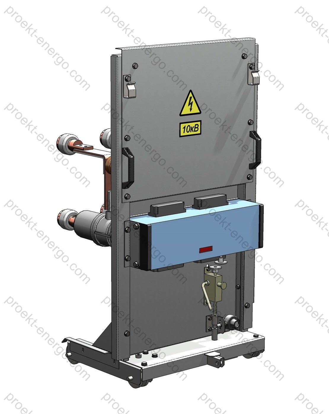
The concept maximizes reuse of the existing K-104 cubicle metalwork and retains the standard switchgear architecture. The retrofit supply includes: a new withdrawable unit on rails with the breaker operating mechanism; adapters/transition plates for the contact system; a shutter mechanism with guides and dampers; the earthing switch operating mechanism (if mounted on the door - compatibility with the controls is ensured); a set of shutters and louvers for the truck compartment; updated locks/key interlocks; the secondary interface (terminal blocks, harnesses, connectors) with marking; a set of nameplates and warning labels.
The circuit-breaker - vacuum (preferred) or SF6 - is selected by input data: rated voltage 6/10 kV, frequency 50/60 Hz, rated current 630–3150 A, short-circuit breaking current 20–31.5 kA (higher on request), mechanical endurance, compatibility with protection schemes (electromagnetic/spring mechanisms), remote control/position indication/diagnostics options. Solutions with embedded poles are available to improve resistance to humidity and dust; modular mechanisms with reduced maintenance are possible. The withdrawable unit implements mechanical and electrical interlocks for doors/earthing switch/racking to prevent mal-operations. Main-circuit contacts are silver-bearing with spring loading, designed for repeated racking-in/out cycles and frequent engage/disengage operations.
Layout provisions include: retaining K-104 elevation marks and racking depths, adjustment of end-stops and limit switches, unified fasteners (screws, rivets, captive nuts), and reversible modernization - storing the old withdrawable unit as a spare. The shutter mechanism uses impact-resistant dielectric material with UV and ageing stability; interlock drives have service windows for inspection. For enhanced reliability, secondary circuits use spring-clamp terminals with 5.08 mm pitch; harnesses are made of heat-resistant wires with dual marking (signal and functional); all circuits are supplied with up-to-date schematics and connection tables.
Integration of modern protection and control IEDs (IEC 61850-ready, PLC/SCADA options) is performed in the existing relay compartment or in a supplied auxiliary cabinet. Options include built-in current/voltage transformers (incl. compact sensors) and temperature/partial-discharge sensors for condition monitoring. To improve dielectric performance, a barrier screen between phases and phase-to-earth is provided, along with an optimized internal airflow path.
Safety
Personnel safety is ensured by a comprehensive set of measures: mechanical and electrical interlocks, inter-door latches, key-to-key systems, forced removal of control power when switched to the test/maintenance position, earthing with a visible isolation gap, phase-to-phase and phase-to-earth barriers, protective shutters that automatically close when the unit is racked out. Correct position is verified by limit switches with panel indication. Fire-safety pictograms and EHS instructions are applied on the doors; labels indicate short-circuit categories and the IAC class where applicable to the specific solution.
To mitigate arc-flash damage, the design provides: reinforced panels in potential impact zones, pressure relief ducts, doors on heavy-duty hinges, and high-strength latching. If required, the project can include optical arc-flash sensors with high-speed tripping (via the protection IED) and arc-mitigation solutions. The degree of enclosure protection is selected per site conditions (for indoor installations typically not lower than IP3X on the external surfaces and IP2X in service areas; IP4X/IP54 for the relay-compartment doors on request). All warning signs and labels are provided in Russian with international symbols duplicated.
Manufacturing options
We offer three typical modernization scenarios. The choice depends on schedule, budget, testing requirements and the desired level of fleet unification. In practice, a mixed strategy is common: a “fast-track” start for critical feeders by installing a new withdrawable unit, followed by stepwise adaptation of the remaining ones.
| Option | Essence of the solution | Pros | Features / limitations |
|---|---|---|---|
| Adaptation of the existing withdrawable unit | Mounting a new breaker on the original chassis with an adaptation kit, interlock and secondary rewiring, insulation checks. | Lowest cost; familiar mechanics retained; brand-flexible breaker choice. | More on-site mechanical work; precise alignment required; longer duration; type testing is limited (FAT and dielectric/routine tests performed). |
| New withdrawable unit assembly | Delivery of a new chassis with breaker, shutters, interlocks and harnesses; dimensions and interfaces compatible with K-104. | Fast commissioning; minimal site work; old unit kept as a spare; easier maintenance. | Slightly higher cost; requires logistics/storage. |
| Factory “retrofill”/“hard-bus” module (One-Fit-class / equivalent) | Integrated module with implemented contact interfaces, shutters, interlocks and extended type-test program. | Very short outage; improved dielectric performance; standardized maintenance; high installation repeatability. | Dimensional compatibility required; fixed scope; higher price but predictable outcome. |
Standards compliance
The retrofit project targets alignment of the switching part with current international/ harmonized standards. Depending on configuration and test program, the following may be applied:
- IEC 62271-1 - common requirements for medium-voltage switchgear and controlgear (service conditions, insulation coordination, tests).
- IEC 62271-100 - AC circuit-breakers above 1 kV (breaking classes, short-circuit parameters, test-duty cycles).
- IEC 62271-102 - disconnectors and earthing switches (visible isolation gap, interlocks, mechanical strength).
- IEC 62271-200 - metal-enclosed switchgear up to 52 kV (classification, compartments, internal arc classification IAC, enclosure IP).
- IEC 60529 - degrees of protection (IP code for doors, compartments and controls).
- For digitalization: IEC 61850 - substation communications (on request).
Contracting and partnerships
We are open to cooperation with contractors, electrical equipment manufacturers, automation integrators and investors interested in producing/localizing similar solutions. Engagement formats: licensing of the design documentation set with author support; joint pilot batch followed by serial production; OEM assembly of withdrawable units under your brand; contract manufacturing of individual assemblies (shutters, chassis, contact adapters, interlock drives). We provide manufacturing recommendations for blanks/machining, tolerance and fit charts, alignment templates, coating/painting requirements, routing sheets and QC checklists.
Documents
The documentation set is project-specific and includes: general assembly drawings of the withdrawable unit; BOMs with consumption norms; secondary wiring diagrams and cable schedules; mechanical and electrical interlock schemes; instructions for mounting/aligning the contact system; test programs and procedures (dielectric, routine, interlock verification, insulation clearances check); O&M documents (datasheet, manual, spare parts lists); 3D models and flat DXF for CAM. Formats: DWG/DXF, PDF, DOCX, XLSX; 3D - STEP/Parasolid; optionally - SolidWorks (SLDPRT/SLDASM), eDrawings.
Project stages
- Site survey of K-104 switchgear and collection of input data (ratings, SC currents, schematics, busbars/cables, dimensions, condition).
- Engineering of the withdrawable unit layout, breaker and interlock selection, agreement of a typical solution.
- Manufacturing of chassis/shutters/adapters, preparation of secondary harnesses, marking, QC.
- Factory tests of the withdrawable unit and breaker (FAT/routine dielectric, functional checks, interlock verification).
- Delivery / installation on site, alignment of the contact system, travel/force checks, labeling update.
- Commissioning, staff training, hand-over of O&M documents and spares.
- Service: maintenance schedule, life-cycle monitoring, supply of spares and upgrade kits.
Economics and timelines
Compared with full switchgear replacement, retrofit reduces direct CAPEX and indirect costs related to long outages, dismantling, construction work and room re-certification. In a typical project, the share of re-used assets (steelwork, busbars, cables, foundations, door assemblies) reaches 60–80% of the cost of new switchgear, directly lowering TCO. Feeder energization after delivery of the assemblies can take from a few hours to 1–2 shifts (depending on the option selected and the scope of checks).
FAQ
Can the old plug-in tulip contacts be kept? In most cases, a new set of contact clusters compatible with the K-104 busbar system is supplied, improving contact pressure stability and reducing heating.
Are the new breakers compatible with the door/earthing interlocks? Yes, interlocks are tuned to the standard kinematics and key systems; new interlock mechanisms with keys can be supplied if needed.
How are tests arranged? Factory (FAT, insulation, functional) and site acceptance tests are performed; the list and scope are per the agreed test procedure. When a factory “retrofill” is chosen, part of the checks is covered by the manufacturer’s type tests.
Why work with us
- No need to maintain a large in-house engineering team - you receive a complete documentation set for the product that can be handled by a mid-level engineer.
- No need to build pilot prototypes - our experience enables immediate launch of serial batches.
- Working to our documentation, your team will receive consulting on all nuances of replacing the K-104 withdrawable unit.
For additional information on the K-104 withdrawable unit replacement (retrofit), please contact: inbox@proekt-energo.com
PDF - Download the technical information on the K-104 withdrawable unit replacement


