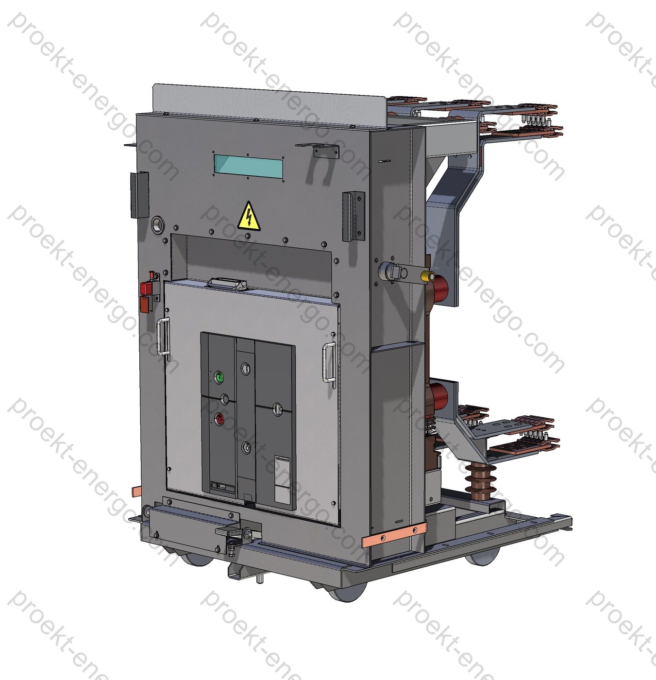
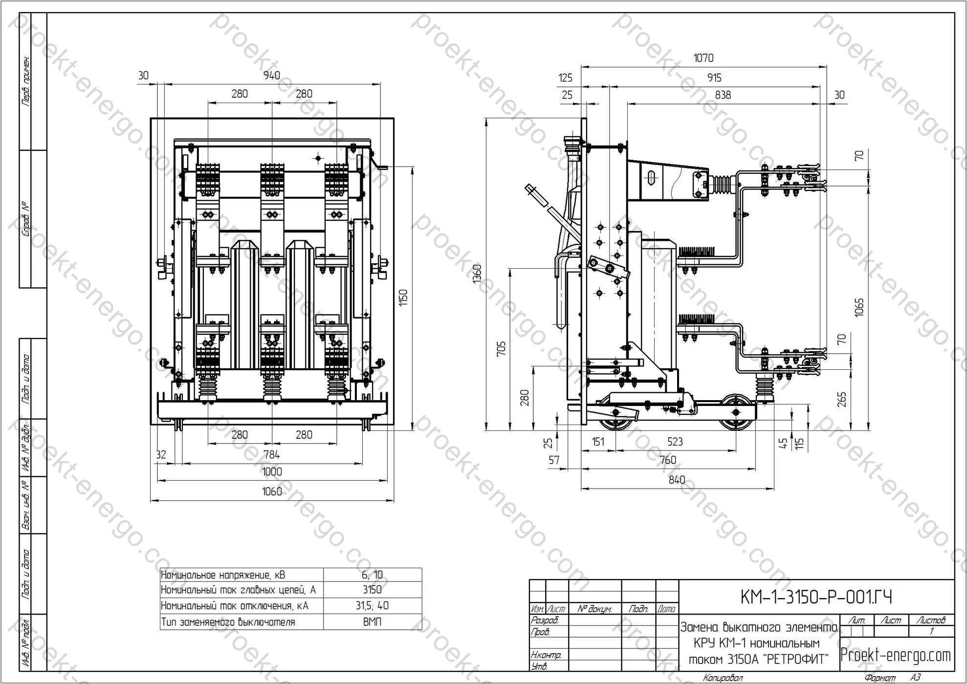
KR U KM-1 rated current 3150 A - withdrawable unit replacement (retrofit)
Retrofit is the modernization or partial re-equipping of MV switchgear (KRU/KSO) by replacing life-expired devices with modern solutions without a full replacement of switchboards and bus systems.
First of all, the upgrade targets the most stressed and critical component - the oil circuit-breaker. It is replaced with a modern vacuum or SF₆ circuit-breaker with a spring-charged or electromagnetic mechanism; unlike oil breakers, these do not require routine oil/contact overhauls, provide higher switching endurance, and have predictable maintenance intervals. A comprehensive switchgear upgrade is also possible: block replacement of the compartment including the withdrawable unit (truck), shutter mechanism, earthing-switch drive, doors, relay cabinet, as well as modernization of the secondary protection/control circuits (migration to microprocessor-based relays).
The reliability of KRU or KSO is directly determined by the condition of its switching apparatus. Such modernization is a straightforward and economical way to compensate for wear of breakers in legacy distribution gear and to bring operation in line with current safety requirements. Retrofitting existing electrical equipment is more cost-effective than purchasing new gear, does not require large-scale construction/installation works, and reduces losses from forced downtime; periodic repairs on old breakers do not ensure the required level of availability. Other cell elements, if in satisfactory condition, can remain in service.
Purpose and application
Replacing the withdrawable unit in KM-1 switchgear with a rated current of 3150 A is intended to restore lifecycle and increase operational reliability of medium-voltage distribution systems in industrial, utility, energy, municipal and infrastructure networks. The solution targets bus-section and bus-tie cubicles, incoming/feeder cubicles with elevated current loads, supplies for large motor loads (pump stations, compressor and ventilation units, mills), as well as panels with frequent operations (auto-reclosing/automatic transfer - AR/ATS).
Retrofit is applied during reconstruction of 6–10 kV substations (adaptation to other voltage levels is possible as per project), modernization of main and distribution switchboards, within industrial revamping programs, for mines and pits, transport-infrastructure upgrades, and when migrating distribution equipment to modern requirements for reliability, electrical safety, and condition-based diagnostics.
Typical use cases: replacement of oil circuit-breakers with exhausted service life; migration to vacuum breakers with high electrical/mechanical endurance classes; fleet unification of breakers and mechanisms; introduction of microprocessor-based protection and monitoring; reduction of operating costs and improvement of energy efficiency by lowering technical losses.
Technical data
| Parameter | Value/Range | Note |
|---|---|---|
| Rated current of withdrawable unit | 3150 A | 2500/4000 A configurable by project |
| Rated voltage | 6 or 10 kV | Other levels - on request |
| Frequency | 50 Hz | 60 Hz - on request |
| Rated short-circuit breaking current | up to 31.5 kA | Depends on the selected breaker |
| Endurance class (IEC) | E2/M2 | Electrical/mechanical endurance |
| Opening (trip) time | ≤ 60–80 ms | Depends on operating mechanism |
| Degree of protection (enclosure) | IP3X–IP4X | For indoor installations |
| Interlocking system | Mechanical + electrical | Prevents incorrect operations |
| Mechanical endurance | 10,000–30,000 operations | Per breaker manufacturer’s data |
| Operating mechanism type | Spring-charged / electromagnetic | With self-monitoring circuits |
| Interrupting medium | Vacuum / SF₆ (for certain options) | Selection per specification |
| Temperature rise at contact joints | Within allowable limits | Verified by heat-run tests |
| Condition monitoring/diagnostics | Option | Temperature sensors, operation counters, communication interfaces |
| Mass of the withdrawable unit | From 120 kg | Depends on configuration |
| Manufacturing lead time | from 4–8 weeks | Clarified per current production load |
Note: values are typical and are refined for a specific project depending on the chosen breaker model, short-circuit levels, and environmental/climatic execution.
Service conditions
The withdrawable unit supplied within the retrofit project is designed for service conditions typical of 6–10 kV indoor MV switchgear: ambient temperature from -10…-5 °C to +40…+45 °C (the exact range is confirmed by project and breaker type), relative humidity up to 80–90% at +20 °C without condensation, installation altitude up to 1000 m a.s.l. (dielectric-strength correction factors apply above this). Operation is permitted in environments free of chemically active gases, conductive dust, and explosive mixtures. Vibration severity - normal for indoor switchgear; elevated vibration is agreed additionally. Housekeeping and cleanliness shall meet applicable O&M practices for medium-voltage switchgear.
The degree of protection of panels and doors generally conforms to IP codes for indoor installations (e.g., IP3X/IP4X for the enclosure and IP2X in secondary-circuit areas). The retrofit does not degrade the original dust/moisture protection; if required, the project provides new seals, additional barriers, shutters, and ventilation filters, as well as versions for increased humidity and dust. For rooms with condensation, space heaters and their control by thermostat/hygrostat are provided.
Layout and design solutions
The withdrawable unit for KM-1 3150 A is engineered to fit existing overall and interface dimensions, retaining the geometry of power contact fingers, centerline heights, insertion stroke, and interlock kinematics. Depending on the chosen modernization strategy, the following configurations are used:
- Adaptation kit for the existing withdrawable unit. Includes power-contact adapters, transition plates, new feeders and busbars, rework of latching points, restoration of dielectric clearances, replacement of secondary plugs/connectors, and overhaul of the running gear. Contact pressure is adjusted; checks include contact resistance and temperature-rise, and verification of open/close travel.
- Full replacement of the withdrawable unit. A new “cartridge” is manufactured with a factory-installed vacuum or SF₆ breaker, integrated shutters, interlock elements, and mechanical position indication. The design replicates mounting points and avoids any welding on the cell body.
- Factory “block-in-block” module (typical One-Fit-class solutions). A frame module with integrated adapters, metering/measurement transformers or sensors as per project, diagnostics modules, an upgraded shutter mechanism, and an interface for microprocessor protection terminals. The package shortens commissioning time and improves fleet uniformity.
The support frame and current-carrying parts are made of copper bars with silver/tin plating and non-flammable spacers that maintain stable contact pressure. To exclude local overheating, adjustable clamps are used together with additional guides and stops to prevent skewing during racking-in/out. Insulating spacers are made of GFRP/DPK with high creepage distances; edges and radii are coordinated with requirements for dielectric strength and partial discharges.
Secondary circuits are modernized for contemporary protection/control terminals (analog/digital inputs, digital outputs, communication interfaces). Where required, “plug-in” connectors are provided to speed up removal, with labeled harnesses, terminal blocks, interlock relays, and local/remote-control schemes. Interlocking logic is programmed: blocking racking-in with earthing switch closed, blocking closing with shutters open, door interlocks, mutual interlocks with bus-section cubicles, etc.
The shutter mechanism safely isolates the main busbars when the truck is withdrawn and prevents access to live parts; viewing windows and position indicators are provided. The earthing-switch mechanism is manual or motor-operated, with limit switches, mechanical/electrical interlocks, and “Earthed/Disconnected” indication.
Safety
The retrofit project is oriented toward compliance with modern electrical-safety requirements and arc-fault protection practices. The layout and interlocks preclude personnel misoperations; safe-access service zones are provided. Modern circuit-breakers are used with higher switching endurance, fast opening times, built-in self-monitoring, and the ability to diagnose mechanism and contact-system condition. Integration of arc-flash protection (optical/fiber or sensor-based), temperature sensors on bolted joints, event loggers, and network interfaces for SCADA is available by project.
Design measures maintain dielectric clearances and creepage distances, shield secondary circuits from fault currents, and provide systematic bonding/earthing of metal parts and doors. At the Customer’s request, infrared thermography is performed after commissioning and during trial operation, as well as power-frequency and/or VHF withstand tests in accordance with the test program.
Manufacturing and delivery options
- Supply of an adaptation kit to install a new-type breaker on the existing withdrawable unit: transition plates, power adapters, installation kit, modernization scheme, and alignment worksheet.
- Supply of a new withdrawable unit “turn-key”: assembled truck, installed breaker, shutters, interlocks, connectors, spare-parts kit; only minimal panel rework required.
- Supply of a factory “frame module”: a standardized solution with extended diagnostics and a pre-validated set of interlocks and interfaces.
| Retrofit option | Implementation time | On-site work scope | Approx. cost | Pros/Features |
|---|---|---|---|---|
| Adaptation kit for existing withdrawable unit | Medium | High (alignment, setup) | Minimal | Maximum reuse of existing parts; flexible for non-standard cells |
| New withdrawable unit | Short | Low | Medium | Series assembly, fast replacement, predictable result |
| “Block-in-block” frame module | Short | Low | Above medium | Built-in diagnostics, standardized solutions, minimized risks and downtime |
Standards compliance
The retrofit is oriented to the applicable requirements for medium-voltage switchgear and switching devices. The most relevant standards used in design and supply:
- IEC/EN 62271-200 - metal-enclosed AC switchgear 1…52 kV (design rules, type tests, internal arc performance).
- IEC/EN 62271-100 - AC circuit-breakers (rated duties, mechanical/electrical endurance, duty cycles).
- IEC/EN 62271-102 - disconnectors and earthing switches (mechanics, interlocks, making/withstand of earthing switches).
- IEC 62271-1 - common specifications for high-voltage switchgear and controlgear (nameplate data, marking, climatic allowances).
- IEC 60529 - degrees of protection (IP code) for enclosures, indoor.
- (As applicable) IEC/EN 61869 - instrument transformers; IEC/EN 60255 - protection relays and automation.
Engagement of contractors and partners
We invite electrical-equipment manufacturers, metalworking production sites, and investors interested in serial production of retrofit kits for withdrawable units for KM-1 3150 A switchgear. The partnership model provides licensed transfer of the complete set of working documentation, process charts, routing sheets, and BOM/cutting lists, personnel training, support for initial series, as well as co-branding and service support at the place of operation. Contractors can perform machining, plating, painting, subassembly, and electrical testing - with subsequent shipment of completed trucks to the Customer or to our consolidation warehouse.
Documents
We provide a complete documentation package for tenders and manufacturing:
- Preliminary package: technical proposal, questionnaires, list of applied equipment, 3D visualizations, consolidated cost and lead-time estimate.
- Working documentation: general views, assembly drawings, parts lists, lists of purchased items, single-line and schematic diagrams, wiring diagrams, interlock and control-logic schemes.
- Manufacturing models: 3D (STEP/Parasolid), 2D (DWG/DXF), process sketches, inspection cards, list of normative docs; formats: AutoCAD, SolidWorks, Parasolid, DXF, DWG.
- Operation documentation: user manuals, installation & maintenance instructions, procedures for contact-pressure alignment, Poka-Yoke checklists for switching operations, test programs & methods, FAT protocols, and commissioning checklists.
Project stages
- Survey of the existing KM-1 cubicle, measurement of baseline dimensions, photo documentation of assemblies, retrieval of electrical diagrams.
- Design of the adaptation kit/new truck, 3D-model approval, release of working documentation.
- Manufacturing, factory tests, quality control, packing.
- Delivery to site, dismantling/installation, alignment, connection of secondary circuits.
- Commissioning, verification of interlocks, functional and electrical tests.
- Personnel training, handover of operation documentation, support during the warranty period.
Economic efficiency
Retrofit can reduce CAPEX by 40–70% compared to full switchgear replacement, shorten downtime, shift part of the work to shop conditions, and lower OPEX by eliminating oil-system servicing and routine overhauls of legacy mechanisms. Additional benefits include higher equipment availability, shorter restoration time after faults, and the introduction of predictive-maintenance tools.
FAQ
Can the existing busbars/leads be retained? In most cases - yes, provided contact surfaces are restored and thermal performance is confirmed. Overheated/loosened joints detected during survey are replaced.
What about protection relays? At the Customer’s request, secondary circuits are migrated to microprocessor-based terminals with remote monitoring, event logging, settings management, and self-diagnostics.
Are construction works required? As a rule, no. The “no modification to the cell body” concept minimizes construction/installation works; if the enclosure is heavily worn, local replacement of doors/fascia elements is possible.
- Preliminary technical documentation for participating in tenders for replacement of the withdrawable unit of KM-1 3150 A switchgear. We will prepare the information you need to assess manufacturability in line with tender requirements and questionnaires.
- Working drawings, 3-D models, and other necessary documentation to manufacture the withdrawable unit of KM-1 3150 A switchgear at your facility. If you do not plan to fabricate parts in-house, we will help place orders at partner shops. Your plant will perform final assembly and installation.
- All documentation, where necessary, is adjusted to project requirements and to your facility’s technological capabilities.
- If other manufacturers’ equipment is installed at the substation, we will prepare documentation for producing compatible equivalent equipment in addition to the installed base.
Advantages of working with us
- No need to maintain a large team of highly qualified design engineers - you receive a documentation set for the product that can be used by a mid-level engineer.
- No need to build prototypes - our experience allows launching serial production successfully from the start.
- Working to our documentation - your specialists will receive consultation on all nuances of replacing the withdrawable unit of KM-1 3150 A switchgear.
For additional information on replacement of the withdrawable unit of KM-1 3150 A switchgear (retrofit), please contact: inbox@proekt-energo.com
PDF - Download technical information on replacement of the withdrawable unit of KM-1 3150 A switchgear


