RVZ-10 (RV-10) Indoor Disconnector
RVZ-10 (RV-10) indoor AC disconnectors are used for making and breaking, without load, individual sections of medium-voltage networks rated 6 or 10 kV, as well as for earthing de-energized sections by means of fixed earthing blades. Applications:
- Prefabricated transformer substations (KTP);
- Unit switchgear cubicles with single-sided service (KSO);
- Metal-enclosed switchgear (KRU);
- KRUN;
- Mobile prefabricated transformer substations;
- Main distribution boards (MDB);
- Capacitor banks;
- Incoming and distribution panels.
Disconnector range:
- RVZ-10/400 – disconnector rated current 400 A;
- RVZ-10/630 – disconnector rated current 630 A;
- RVZ-10/1000 – disconnector rated current 1000 A;
- RVZ-10/2000 – disconnector rated current 2000 A.
The disconnector is manufactured as a three-pole unit with fixed earthing switches (RVZ-10) or without earthing switches (RV-10). Mechanical interlocking prevents incorrect operations: the earthing switch cannot be closed when the main blades are closed; the main blades cannot be closed when the earthing switch is closed. Rotation of the operating shafts of the main circuit and the earthing switch is manual - via PR manual operating mechanisms. Disconnectors are produced with rated currents up to 2000 A.
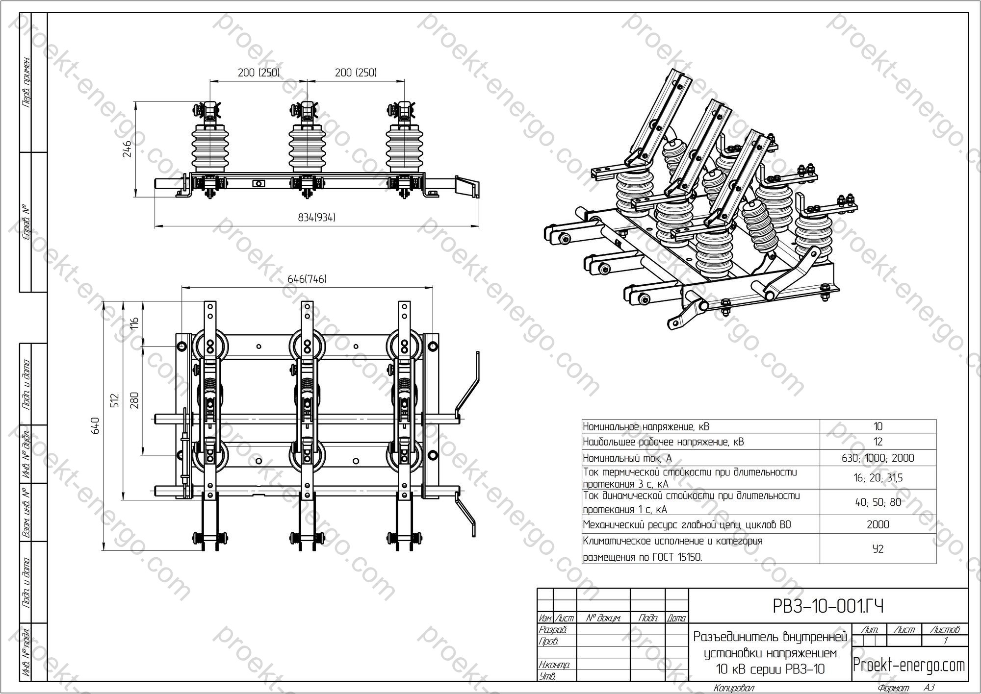
Technical data
| Rated voltage, kV | 6; 10 |
| Highest voltage for equipment (Um), kV | 7.2; 12 |
| Rated current, A | 400; 630; 1000; 2000 |
| Rated short-time withstand current (3 s), kA | 16; 20; 31.5 |
| Rated dynamic withstand current (1 s), kA | 40; 50; 80 |
| Mechanical endurance of main circuit, O–C operations | 2000 |
| Climatic design and location category per GOST 15150 | U2 |
Purpose and application
RVZ-10 (RV-10) is a three-pole vertical-break (swing-link) switching device that provides a visible isolating gap and ensures safe operational isolation and earthing of medium-voltage networks 6–10 kV. The disconnector is intended for:
• localization and selective outage of individual feeders, busbar sections and connections in KSO/KRU;
• creating maintenance gaps with visual indication of blade position;
• safe connection and testing of standby lines, busbar sectionalizing, isolation of metering and measurement nodes;
• bus-coupler and bus-reserve schemes, as well as switching capacitor banks without load;
• earthing of de-energized sections by built-in fixed earthing blades (for RVZ versions).
Thanks to its modular layout and universal connection dimensions, RVZ-10 series disconnectors fit most standard KSO cubicles (single- or double-sided service), metal-enclosed switchgear KRU/KRUN, and complete substations (fixed and mobile) both at 6 kV and 10 kV. The design is oriented for integration with widely used PR manual mechanisms and three-position schemes “ON - OFF - EARTHED”, which simplifies fleet unification and reduces total cost of ownership.
Operating conditions
Climatic design - U2 according to GOST 15150, for operation in temperate climates indoors with free air access or under a shelter. Location - category 2. The insulation, contact assemblies and support insulators are designed for the specified service and test stresses for switchgear with voltage classes 6 and 10 kV at 50 Hz. Installation is permitted up to 1000 m above sea level without recalculation of insulation levels; for elevations above 1000 m the dielectric requirements are addressed by project documentation (in line with general provisions for MV switching devices). The disconnectors are intended for 50 Hz networks with standardized temperature, humidity and dust levels within the location category, and for operation inside KSO/KRU metal cubicles with natural ventilation. Screwed and pinned joints are protected against self-loosening under vibration, and moving parts are designed for long service without disassembly, subject to periodic maintenance.
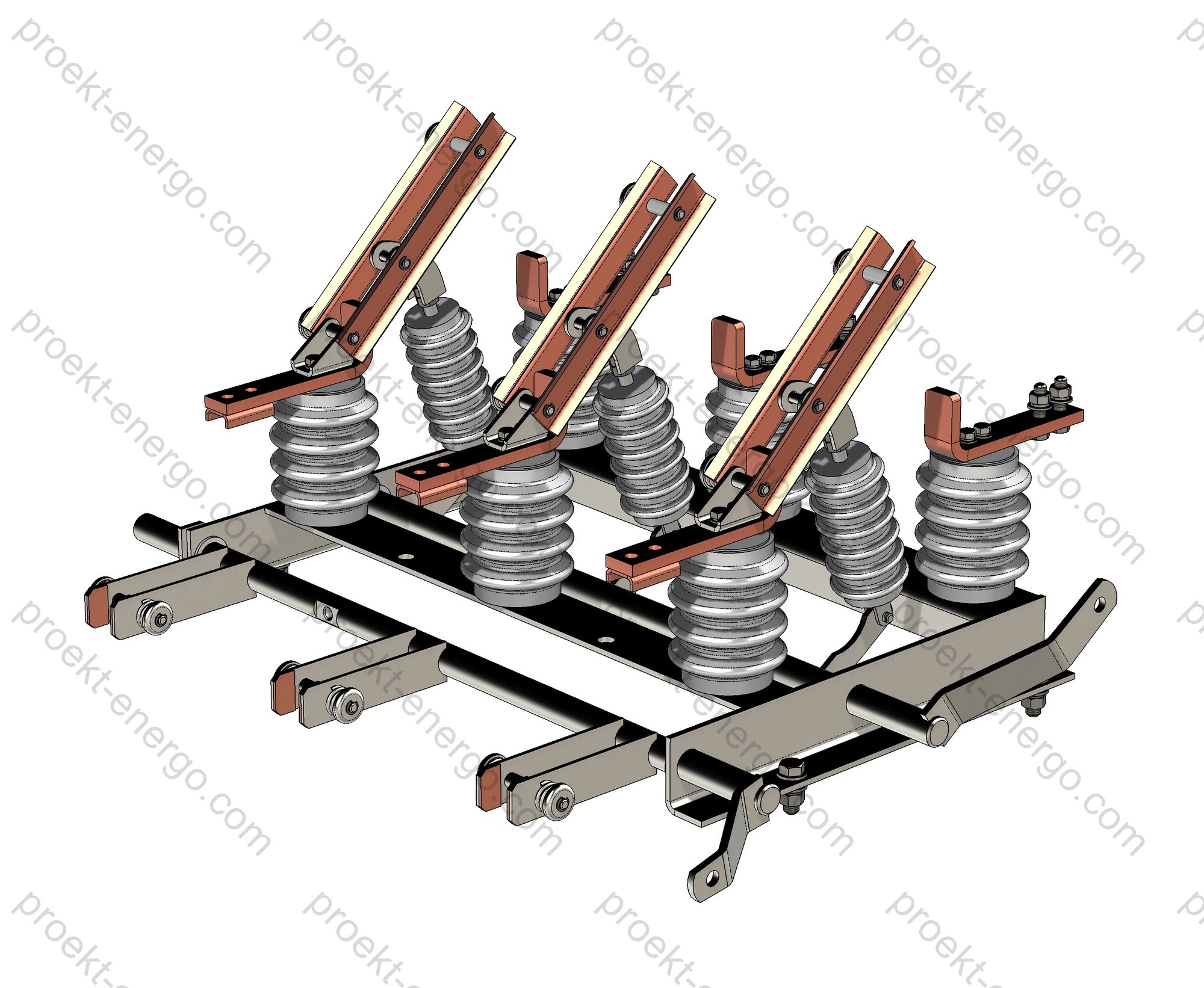
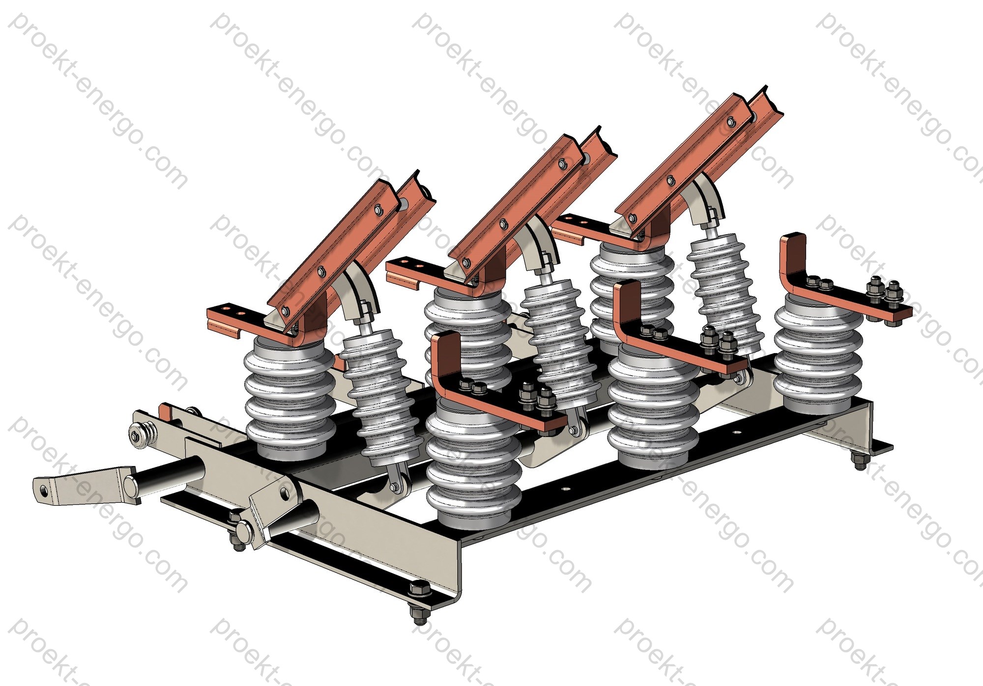
Layout and design solutions
The RVZ-10 disconnector is a three-pole assembly on a common welded frame. Each pole includes:
• support (or bushing - in the RVFZ variant) insulators of increased mechanical strength;
• a swinging current-carrying blade made of copper or aluminum alloy with anti-oxidation coating; contact surfaces may be galvanically hardened (e.g., silver-plated) to reduce contact resistance;
• fixed and moving separable contacts with multi-finger spring packs providing stable contact pressure throughout service life;
• main-circuit shaft and earthing-switch shaft (for RVZ) with synchronizing linkage and positive end-position latches;
• mechanical end-stops, position indicators (“ON”, “OFF”, “EARTHED”) with the option to transmit status to the cubicle mimic diagram.
The three-pole unit is mounted on a base (frame) with standardized fixing holes for installation in typical KSO/KRU frameworks. Layout variants allow the earthing switch to be on the separable (fixed) side or on the hinged (moving) side - depending on the connection scheme. The design allows left- or right-hand mechanism placement and compatibility with standard cubicle transmissions. Contact systems are rated for the specified short-time and dynamic withstand currents; contact resistance remains stable due to a self-wiping effect during operation and optimized blade geometry. Multi-point contact sockets and flexible connectors are used at high-current locations.
The PR manual three-position mechanism, installable on the cubicle door, provides:
- “ON” (main blades closed, earthing switch open);
- “OFF” (visible isolation of the main circuit);
- “EARTHED” (main blades open, earthing blade closed).
The kinematics exclude simultaneous closure of the main circuit and the earthing switch. Provision is made for padlocks (up to 3 pcs) for organizational lockout. Position is shown by mechanical indicators and/or by a microswitch for auxiliary signalling to SCADA.
Safety and interlocks
The interlocking system prevents hazardous operations: with the main blades closed it is mechanically impossible to close the earthing switch, and vice versa - with the earthing switch closed the main blades cannot be closed. Mechanical stops prevent incomplete make/break. A visible isolating gap and reliable position latching improve personnel safety during switching and maintenance. The mechanism has holes for padlocks and seals, enabling lockout/tagout as required by work permits. The design withstands short-circuit forces within the rated short-time and peak withstand values; earthing components have thermal and mechanical margins. On request, additional shrouds and barriers can be installed, as well as key interlocks with other apparatus (e.g., a load break switch mechanism) to enforce the required sequence of operations.
Versions and options
The RVZ-10 series includes basic and extended versions for standard cubicles and special applications:
• RV-10 - without earthing switch (main circuit only);
• RVZ-10 - with one fixed earthing switch (on the separable side or on the moving side);
• RVZ-10 (double-earthing version) - per project for special sectionalizing tasks;
• version with bushing insulators (RVFZ analogue) - for applications requiring enhanced wall-through insulation;
• left/right mechanism, extended linkages, versions for various phase spacings;
• remote mechanical position indicators, electrical limit switches, contact for “abnormal” blade position;
• supply with flexible busbars/bus bridges and a set of mounting hardware;
• protective covers for live parts and local shields. Installation and connection
Standards compliance
The design and test requirements are aligned with applicable international and national standards for AC disconnectors and earthing switches. The following standards are taken into account during design and testing:
• IEC 62271-102 - “High-voltage switchgear and controlgear - Part 102: Alternating current disconnectors and earthing switches”;
• IEC 62271-1 - “High-voltage switchgear and controlgear - Part 1: Common specifications”;
• IEC 62271-200 - “Metal-enclosed switchgear for rated voltages above 1 kV” (as applied to the cubicles housing the device);
• GOST R 52726-2007 - “AC disconnectors and earthing switches above 1 kV and their operating mechanisms”;
• GOST 1516.1 - “AC equipment from 3 to 500 kV. Insulation withstand requirements”;
• GOST 15150 - “Climatic design and location categories” (U2).
Documents
Typical supply set includes: three-pole disconnector on a frame (per agreed configuration), PR manual mechanism with linkages, mounting hardware set, data sheet/form, operation manual, and a set of safety posters/labels (as per project). On request: busbar connection kit (flexible bars, bus bridges), additional shrouds for live parts, position microswitches, mechanical indicators, removable lock-keys. To speed up integration, working design documentation and 3D models in popular formats are available.
| Document / model | Format | Purpose |
|---|---|---|
| Set of working drawings | DWG, DXF | Part manufacturing and assembly, fitment into KSO/KRU cubicles |
| 3D models of units and assemblies | STEP, Parasolid, SLDPRT/SLDASM | Dimensional and kinematic coordination, digital mock-up |
| Bill of materials (BOM) | XLSX, PDF | Procurement planning, costing |
| Data sheet / O&M manual | Operation and maintenance |
Engaging contractors and partnership
We are open to cooperation with manufacturers of electrical equipment, design and installation companies, as well as investors interested in organizing serial production of 6–10 kV disconnectors. We provide preliminary and working documentation packages and technical support for ramp-up: material selection, machining and assembly recommendations, sourcing of cast/forged parts, reference samples. Documentation transfer is accompanied by design-engineer consultations. Adaptation of drawings to your manufacturing capabilities and regulatory requirements is available. We help arrange the cooperation chain: metalworking, electroplating, insulator manufacture, assembly and routine tests. By agreement, we provide personnel training, shop audits and implementation of QC procedures.
Benefits of working with us
- No need to maintain highly specialized engineering staff - you receive a complete documentation set for the product that can be handled by a mid-level engineer.
- No need to build pilot samples - our experience allows launching serial batches straight into production.
- Working to our documentation - your team will receive guidance on all nuances of manufacturing RVZ-10 disconnectors.
- Support at every stage - from preliminary short-circuit and thermal calculations to routine tests and series quality control. Checklists are provided for mechanism setting, contact pressure adjustment, templates for blade-position checks, and operating instructions.
For additional information on RVZ-10 disconnectors, please contact: inbox@proekt-energo.com
...and, as is well known - an error made at the design stage results in 10× costs in manufacturing and 100× in operation...
PDF - Download technical information on RVZ-10 disconnectors


