RV-10/2000; RVZ-10/2000 Indoor Disconnector for currents up to 2000 A
The indoor disconnectors RV-10/2000; RVZ-10/2000 are intended for isolating de-energized sections of an electric circuit that are live, as well as for grounding the isolated sections by means of built-in earthing switches. Rated current - up to 2000 A.
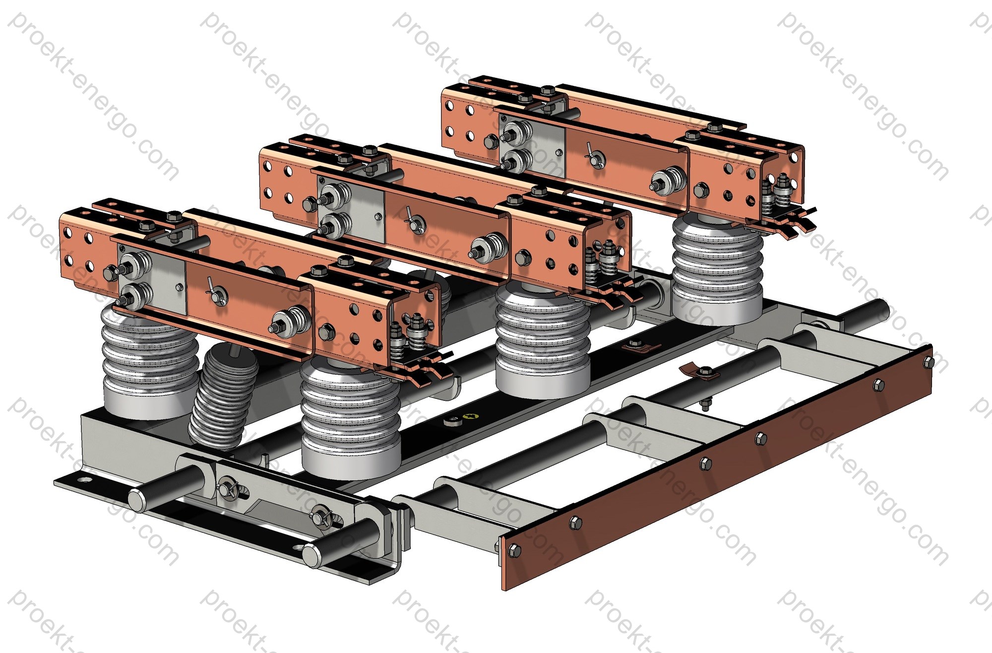
Structurally, these are vertical-break type disconnectors manufactured in a three-pole design.
RV disconnectors are supplied without an earthing switch; RVZ - with an earthing switch on either the separable-contact side or the non-separable side.
The RV/RVZ disconnectors consist of a base frame, support insulators, contact system, pull-rod (operating) insulator and earthing switches. A drive shaft with levers mounted on the frame operates the contact blades. If earthing switches are provided, one or two additional shafts are installed to operate them together with a mechanical interlock that prevents closing the earthing switch with the main blades closed, and vice versa. Insulation comprises support insulators and the pull-rod insulator. The contact system includes copper fixed contacts and moving contact blades. The earthing switch is a copper bar fixed to steel posts welded to the earthing shaft. When operated, the bar engages multi-finger contact blocks mounted on the lower shelves of the fixed contacts. Contact pressure in the axial and separable (blade) contacts of the main blades and in the finger contacts of the earthing switch is provided by springs.
RV/RVZ disconnectors are designed for environmental classification per EN/IEC 60721-3-3 with the following limits:
- altitude not exceeding 1000 m above sea level;
- upper working ambient temperature +40 °C;
- lower working ambient temperature -45 °C;
- relative humidity 80% at +20 °C.
Technical data
| Rated voltage, kV | 10 |
| Maximum system voltage, kV | 12 |
| Rated current, A | 2000 |
| Rated short-time withstand current (3 s), kA | 31.5 |
| Rated peak withstand current, kA | 80 |
| Mechanical endurance of main circuit, O–C operations | 2000 |
| Environmental classification (replacement for GOST 15150 U3) | EN/IEC 60721-3-3 |


Purpose and application
The RV-10/2000 and RVZ-10/2000 disconnectors are part of indoor medium-voltage distribution equipment for 10 kV systems and are intended for safe operational isolation of circuit sections, busbar sections and KRU/KRUN cubicle feeders, as well as for a visibly verifiable break during maintenance and commissioning. The devices are not intended to interrupt load or short-circuit currents and are operated together with circuit-breakers and fuses that perform load and short-circuit switching. The built-in earthing blades (RVZ versions) enable fast and reliable grounding of the isolated section, reducing job-site preparation time and improving electrical safety.
Typical applications: distribution points and substations, main step-down substations, factory and commercial KRU switchgear, sectioning and incomer cubicles, auxiliary service transformer feeders, ATS/ABT bus sectioning, temporary maintenance jumpers. The disconnectors are effective in schemes with high rated currents (up to 2000 A) and elevated requirements for mechanism reliability and a clearly visible isolation gap.
Service conditions
Designed for indoor installations without aggressive gases or conductive dust, under standardized microclimate parameters. Permissible installation altitude - up to 1000 m; for higher sites, increased insulation clearances and reassessment of withstand levels can be provided by agreement. Operating temperature range: -45 °C to +40 °C; relative humidity - up to 80% at +20 °C. Operation under increased vibration and industrial shock is allowed provided the mounting and alignment requirements of the drive mechanism are met. The units withstand short-time thermal stresses (3 s) and electrodynamic forces under short-circuit currents (see technical data above). For dusty rooms, periodic inspection and scheduled cleaning of insulation and contact assemblies are recommended.
Design and construction
Vertical-break (rotating blade) scheme with three support insulators per pole and a common drive for three phases. This kinematic arrangement ensures compactness within cubicle dimensions, minimal interphase distances, low mechanical losses and stable contact force throughout closing travel. Support insulators - porcelain or polymer with increased bending strength; the pull-rod insulator is designed to transmit axial loads from the operating shaft.
The current-carrying system uses copper bars and blades with brazed or welded contact overlays. Fixed contacts employ multi-finger spring contact blocks, providing low contact resistance and self-cleaning of working surfaces during cycling. Contact pressure in axial and separable (blade) joints is provided by spring packs, maintaining stability over the entire temperature range. Blade rotation nodes use bushing-roller bearings with a low friction coefficient; friction points are protected from dust and accessible for inspection.
The welded base frame features high rigidity, reference holes for mounting to the KRU panel/foundation, and adjustment slots for precise pole alignment. The operating shaft exits to the cubicle front for manual or motor-operated drives. For RVZ versions, additional shafts actuate the earthing blades with independent kinematics. Standard supply includes mechanical end-stops, latching of end positions, and an external position indicator “ON/OFF/EARTHED”.
Electrical insulation meets the requirements of 10–12 kV distribution equipment; necessary clearance and creepage distances are provided, with insulator materials and shed profiles selected for indoor installations and the room’s pollution class. Provision is made for holes and pads for bus links, flexible connectors, take-offs to current/voltage transformers and test blocks. Versions with left- or right-hand drive-shaft placement, as well as mirror arrangements for symmetric panels, are available.
Safety and interlocks
Standard mechanical interlocks exclude closing the earthing blades with the main blades closed and prevent simultaneous “ON” and “EARTHED” positions. A latch prevents position change due to vibration. Provisions are made for padlocks and for microswitches (NO/NC auxiliary contacts) to implement electrical interlocks with adjacent equipment (circuit-breakers, transformers, drive cabinets). Clear visual position indicators are brought to the front; direction of rotation and operating angles are standardized for drive unification. The design ensures safe visual confirmation of the visible isolation gap and reliable grounding of the isolated section in accordance with occupational safety and operating rules for electrical installations.
Versions and options
Base versions: RV-10/2000 (without earthing blade) and RVZ-10/2000 (with built-in earthing blade on either the separable or non-separable contact side). Available on request: AC/DC motor-operator; increased mechanical endurance; polymer insulators; additional position auxiliary contacts; silver-plated contact surfaces; reversible drive-shaft arrangement; dimensional variants tailored to specific KRU/KRUN cubicles; bus connection kits; shielding covers for live parts; quick-install kits and alignment templates.
| Option | Description | Purpose / effect |
| Motor-operator | Electrical control with remote position indication | Automation, remote operation, reduced human factor |
| Auxiliary contacts | 2–8 changeover contacts for “ON/OFF/EARTHED” | Interlocking schemes, telesignaling, SCADA/DCS |
| Polymer insulators | High-resilience silicone composites | Weight reduction, pollution resistance, easier service |
| Silvered contacts | Thin Ag layer on working surfaces | Minimal contact resistance, improved corrosion resistance |
| Mirror arrangement | Left/right drive-shaft, reversed kinematics | Convenient layout in different KRU cubicles |
Standards compliance
Design and manufacture follow applicable international and regional standards for medium-voltage switchgear and disconnectors:
- IEC 62271-102 / EN 62271-102 - AC disconnectors and earthing switches (latest edition with amendments).
- IEC 62271-1 - General requirements for medium-voltage switchgear and controlgear.
- IEC 60529 - Degrees of protection (IP Code) for enclosed parts.
- EN/IEC 60721-3-3 - Environmental conditions - Classification of groups of environmental parameters and their severities (indoor, weather-protected locations).
Materials and finishes
Current-carrying parts are made of electrolytic copper with optional tin or silver plating of contact surfaces. Steel frame elements have powder-coat or zinc-rich primer finishes suitable for industrial indoor environments. Stainless fasteners are used in critical assemblies; plastic parts are made of flame-retardant materials meeting the fire-safety requirements of distribution equipment.
| Assembly | Material / finish | Service notes |
| Blade and bars | Copper (Cu-ETP), tin- or silver-plated contact pads | Low contact resistance, oxidation resistance |
| Fixed contact | Multi-finger spring contact blocks | Self-cleaning and uniform force over many cycles |
| Insulators | Porcelain / polymer (silicone) | High mechanical strength, contamination resistance |
| Frame | Steel with powder coating | Corrosion protection, geometric stability |
| Bearing units | Steel/bronze, lubricated per schedule | Durability, smooth mechanism travel |
Contractors and partners
We invite cooperation with electrical equipment manufacturers, mechanical assembly plants, I&C service companies, investors and engineering organizations. We provide a complete set of design and technological documentation, bills of materials and purchase lists, as well as support during production preparation, assembly, commissioning and product acceptance. We are open to joint supplies of components (insulators, finger contacts, drives), localization and cooperation.
Documents
Package contents: outline and mounting drawings, assemblies, manufacturing drawings for units and parts, external connection diagrams, 3D models (STEP/Parasolid), drawings in DWG/DXF (AutoCAD) and SLDDRW/SLDASM (SolidWorks), parts lists and specifications, installation and maintenance instructions, lubrication charts, inspection check sheets. On request we prepare adaptation to your technology: routing sheets, work instructions, tooling and alignment templates, incoming inspection programs for supplied components.
Why work with us
- No need to maintain highly qualified design staff - you receive a documentation set for the product that can be used by a mid-level engineer.
- No need to build prototypes - our experience enables direct launch of serial production batches.
- Working to our documentation, your specialists receive consultation on all aspects of manufacturing RV-10 disconnectors.
For additional information on RV-10/2000; RVZ-10/2000 disconnectors, please contact: inbox@proekt-energo.com
…as is well known, an error made during design turns into 10× the cost in manufacturing and 100× during operation…
PDF - Download technical information for RV-10/2000; RVZ-10/2000 disconnectors


