RKS-3.3 kV DC Overhead Contact Line Disconnector
The RKS-3.3/1250 UHL1 and RKS-3.3/3000 UHL1 DC overhead contact line disconnectors are intended for switching on and off de-energized (no-load) sections of the DC traction contact system of electrified railways while they are live. When equipped with a motor drive, the unit can interrupt-at the maximum service voltage-the currents of auxiliary machines of rolling stock, passenger-coach heating loads, and-in emergency mode-the back-feed currents of adjacent substations.
The RKS-3.3/1250 UHL1 variant additionally provides simultaneous earthing of isolated sections in the “OPEN” position by means of built-in earthing contacts on the rotating column. The disconnectors are manufactured for climatic category UHL, location category 1; for English-language standards this corresponds to EN/IEC 60721-3-4 (stationary use at non-weather-protected locations). The standard drive range includes manual PRZh series drives for local operation and motor PDZh series drives for remote control and automation of contact-system maintenance.
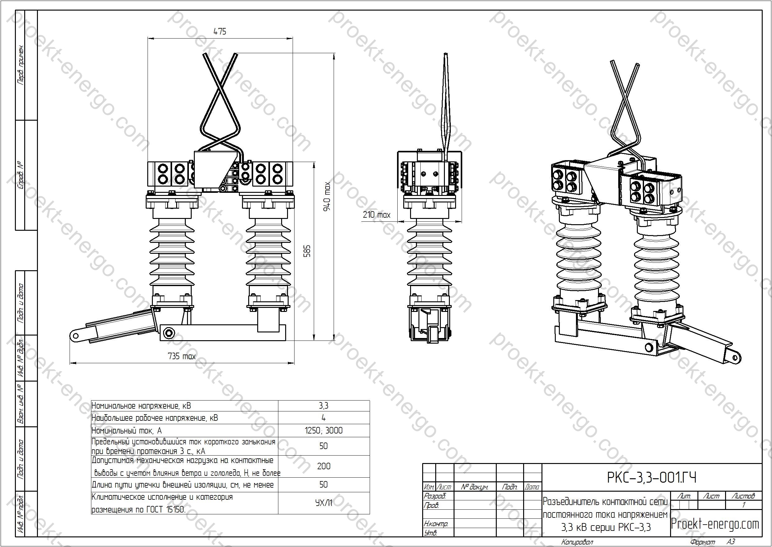
Technical data
| Rated voltage, kV | 3.3 |
| Highest operational voltage, kV | 4 |
| Rated current, A | 1250; 3000 |
| Rated short-time withstand current (3 s), kA | 50 |
| Allowable mechanical load on terminals considering wind/icing, N, max | 200 |
| Maximum current interrupted by motor-operated disconnector, A: – with network inductance 300 mH – with network inductance 35 mH – emergency mode 35 mH |
|
| Creepage distance of external insulation, cm, min | 50 |

Purpose and application
RKS-3.3 is designed for the following functions in DC railway traction power supply systems:
- operational sectioning of the contact system and feeder branches to change feeding modes and improve reliability;
- providing safe working zones for maintenance crews via a clearly visible isolation gap and, where fitted, engagement of earthing switches;
- localization of faulted sections and limitation of short-circuit impact zones;
- switching the no-load currents of auxiliary loads of rolling stock and depot consumers within the permissible interrupting capabilities;
- integration into schemes of sectioning posts, anchor sections, connections to cable inserts and bus bridges of traction substations;
- use in outdoor switchyards (AIS) of traction substations and in support-anchor nodes of the contact system, including as part of a cabinet/stand with drive and interlocks.
The scope covers new and refurbished lines with a rated voltage of 3.3 kV DC, interface nodes of adjacent substations, stabling and maintenance yards, as well as locations requiring remote operation from power-supply or dispatcher control rooms.
Service conditions
The disconnectors are designed for long-term operation across a wide range of climatic factors per UHL1: altitude ≤ 1000 m; upper ambient operational temperature +40 °C; lower operational temperature –60 °C; no icing at wind pressure 1000 Pa (≈ 40 m/s) or operation with ice accretion up to 20 mm at wind pressure 140 Pa (≈ 15 m/s). Clearances and creepage distances of the external insulation ensure reliable operation under high humidity, salt fog and industrial pollution with scheduled maintenance.
Vibration and shock typical for pole-mounted assemblies are mitigated by the rocking-type kinematics, contact spring pressure system and corrosion-resistant fasteners. Mounting is permissible on standalone foundations (base frame) or on embedded platforms of contact-system supports, taking into account wind loads, conductor tension and thermal elongation. For extreme regions, anti-icing components, anti-vandal drive enclosures and cabinet heaters can be supplied.
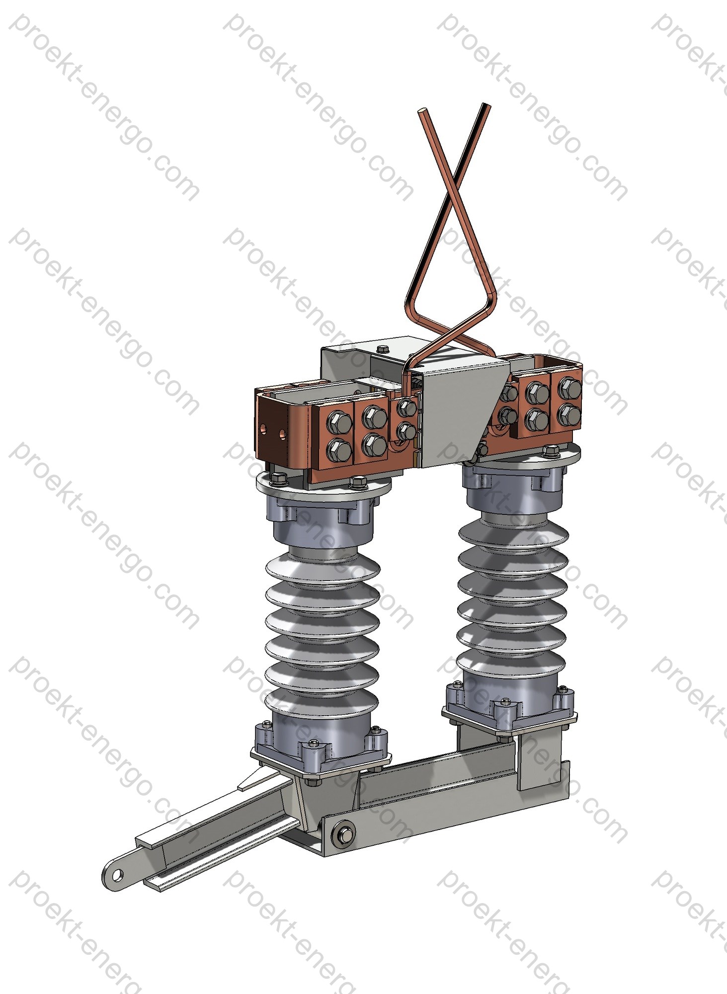
Layout and design solutions
RKS-3.3 is a two-column rocking-type device with a rotating support on one column. Current flows through a fixed contact block and a moving contact blade located on the rotating column. The CLOSED position is ensured by positive contact pressure and rigid kinematics that prevent self-release under dynamic impacts. The OPEN position provides a distinct visible isolation gap, which is critical for issuing work permits.
Main assemblies:
- Base frame (plinth) - welded construction with anti-corrosion protection (hot-dip galvanizing/powder coating per project), with slots for on-site alignment and fixed stops for travel limiters.
- Support/bushing insulators - porcelain or polymer, with increased creepage distance for polluted atmospheres and marine aerosols. A combined scheme is possible: bushing insulator on the incoming side and support insulator on the blade side (per project).
- Contact system - box/lamellar type with silver-graphite or tin contact overlays, spring pressure elements, adjustable closing torque and holding force. Current-carrying parts are copper with galvanic coating; aluminium busbar is permissible with bi-metallic transition pads.
- Earthing device - for RKS-3.3/1250 UHL1 implemented as additional contacts on the rotating column; for the 3000 A version, external earthing switches or the RKSZ variant may be used (per project).
- Kinematic linkage - set of rods, levers and the drive shaft allowing manual operation (PRZh) and remote motor operation (PDZh), with provision for position limit switches “CLOSED/OPEN/EARTHED” and position sensors for SCADA.
The design additionally allows adjustment of angular stops, kinematic balancing to compensate wear and to stabilize transition-time characteristics. Selecting polymer insulation increases resistance to pollution and vibration, reduces weight and simplifies installation on supports with limited load capacity.
Safety and interlocking
A set of mechanical and electrical interlocks prevents erroneous operations. Typical measures include:
- mutual interlocking of the main-circuit drive and the earthing switch to prevent simultaneous “CLOSED” and “EARTHED” positions;
- padlock/key interlocks on drive levers for procedural blocking when personnel are authorized to work;
- limit switches providing reliable discrete indications to SCADA (signals “closed”, “open”, “earthed”, “indeterminate position”);
- a physically visible isolation gap and the possibility to apply portable earthing leads at terminals when performing work (by work permit);
- guards on live parts to prevent accidental contact during drive maintenance.
Versions, drives and options
RKS-3.3 is supplied in basic and extended configurations. For manual operation use the PRZh drive; for remote operation-motorized PDZh drives (adapted to the required kinematics and torque). Options include position sensors, sealed limit switches, cabinet heaters, additional anti-corrosion protection, anti-vandal covers, and transition pads for various busbar and contact-system conductor types.
| Version | Rated current, A | Earthing contacts | Recommended application | Drive type |
|---|---|---|---|---|
| RKS-3.3/1250 UHL1 | 1250 | Integrated on the rotating column | Line sectioning, depots, stabling yards, repair positions | PRZh (manual), PDZh (remote) |
| RKS-3.3/3000 UHL1 | 3000 | Per project: external earthing switch/RKSZ version | High-load sections, feeder incomers, substation interfaces | PRZh (manual), PDZh (remote) |
Installation, connection and maintenance
Install the disconnector on a prepared foundation (frame/bracket on the support) with capability for leveling and alignment to the wire run. Connections to the contact-system conductors are bolted; use bi-metallic adapters when combining copper and aluminium busbars. Before commissioning, check smooth travel, opening angles, contact pressure forces and proper interlock operation. Scheduled maintenance includes periodic visual inspection, tightening of joints, cleaning and, if necessary, light lubrication of moving parts, plus checks of insulation condition and limit switches. For PDZh drives, verify torque and control circuits; for PRZh, inspect rods, joints and latches.
Reliability and service life
Mechanical endurance is achieved through wear-resistant bushings, constant-force spring elements, and kinematics selected to prevent blade sticking under pollution and icing. Thermal robustness of the contact system ensures permissible temperature rise under rated current and short-term overloads typical for the contact system. Coatings of current-carrying parts protect contact surfaces from oxidation and reduce contact resistance, stabilizing heating over lifetime.
Standards compliance
The RKS-3.3 design and operating characteristics take into account applicable international and national standards for DC traction fixed installations and isolating devices:
- IEC/EN 61992-1 - “Railway applications - Fixed installations - D.C. switchgear - Part 1: General requirements”;
- EN 50163 - “Railway applications - Supply voltages of traction systems” (ranges for 3 kV DC systems);
- EN 50122-1 - “Railway applications - Fixed installations - Protective provisions relating to electrical safety and earthing”;
- IEC 62271-102 - “Medium-voltage switchgear and controlgear - Disconnectors and earthing switches” - general requirements for mechanical strength, visible isolation and interlocking;
- EN/IEC 60721-3-4 - Environmental conditions classification (stationary use at non-weather-protected locations), corresponding to climatic category UHL1.
Supply variants and options
| Item | Basic supply | Project options |
|---|---|---|
| Drive | PRZh (manual) | PDZh (motorized), control cabinet, anti-condensation heater, remote indication |
| Insulators | Porcelain support | Polymer/bushing, increased creepage distance |
| Earthing switch | Integrated (for 1250 A) | External earthing switch, RKSZ version (for 3000 A) |
| Signalling | Mechanical indicators | Limit switches “CLOSED/OPEN/EARTHED”, position sensors |
| Protection | Anti-corrosion frame coating | Anti-vandal covers, low-temperature greases, enhanced galvanizing |
Partnering and subcontracting
We welcome cooperation with electrical-equipment manufacturers, installation and engineering companies, and investors interested in equipment for traction contact systems. By agreement, we provide the complete set of working documentation, support industrialization, select subcontractors for assemblies (mechanics, casting, plating, insulation), ensure quality control of finished products and assist in type/acceptance tests. Where required, we adapt design documentation to your plant’s materials and equipment nomenclature.
Documents
Our package includes working drawings, bills of purchased items, specifications, 3D models, milling and laser cutting layouts, and formats for integration with your production: AutoCAD (DWG/DXF), SolidWorks (SLDPRT/SLDASM), Parasolid (x_t/x_b), STEP, and PDF sets for approval. Documentation can be prepared in two options: “for tenders” (general technical solutions, dimensions, characteristics, list of components) and “for manufacturing” (full set of working docs with assembly routes, tolerances and QC requirements).
On request we will prepare SCADA materials (signal lists, wiring diagrams for limit switches, addressing tables), installation and maintenance instructions, as well as passports and logbooks for operation at railway infrastructure facilities.
- Preliminary technical documentation for tender participation to manufacture RKS disconnectors: general technical solutions, diagrams, equipment lists, explanatory notes and data sheets.
- Full set of working drawings, 3-D models and process charts to organize production at your facility. If in-house equipment is unavailable, we will help source assemblies externally (machining, plating, insulation, painting). Final assembly and testing remain on your side.
- Adjustment of documentation to project requirements and your shop capabilities: typical tolerances, material substitutions, fastener unification, specifications of purchased items.
- Compatibility with previously installed equipment from other manufacturers: we will develop interchangeable solutions maintaining schematic and dimensional constraints.
Why work with us
- No need to maintain a large team of senior design engineers: you receive a well-developed documentation set understandable to a mid-level engineer.
- We minimize prototype expenses by using proven assemblies and solutions, enabling serial batches from the first cycle.
- Consulting on all nuances of manufacturing, assembly and commissioning of RKS, support during acceptance tests, assistance with SCADA and staff training.
For additional information on RKS disconnectors, please contact: inbox@proekt-energo.com
PDF - Download technical information for RKS disconnectors.


