KRU "Volga" Medium-Voltage Switchgear 6(10) kV
Purpose and application
KRU "Volga" is intended for receiving, distributing, and switching three-phase power at 6 and 10 kV, 50/60 Hz, in systems with an isolated neutral or a neutral grounded via an arc-suppression reactor/resistor. The standardized bays are designed for indoor substations and industrial power systems where operating safety, serviceability, and layout flexibility are critical.
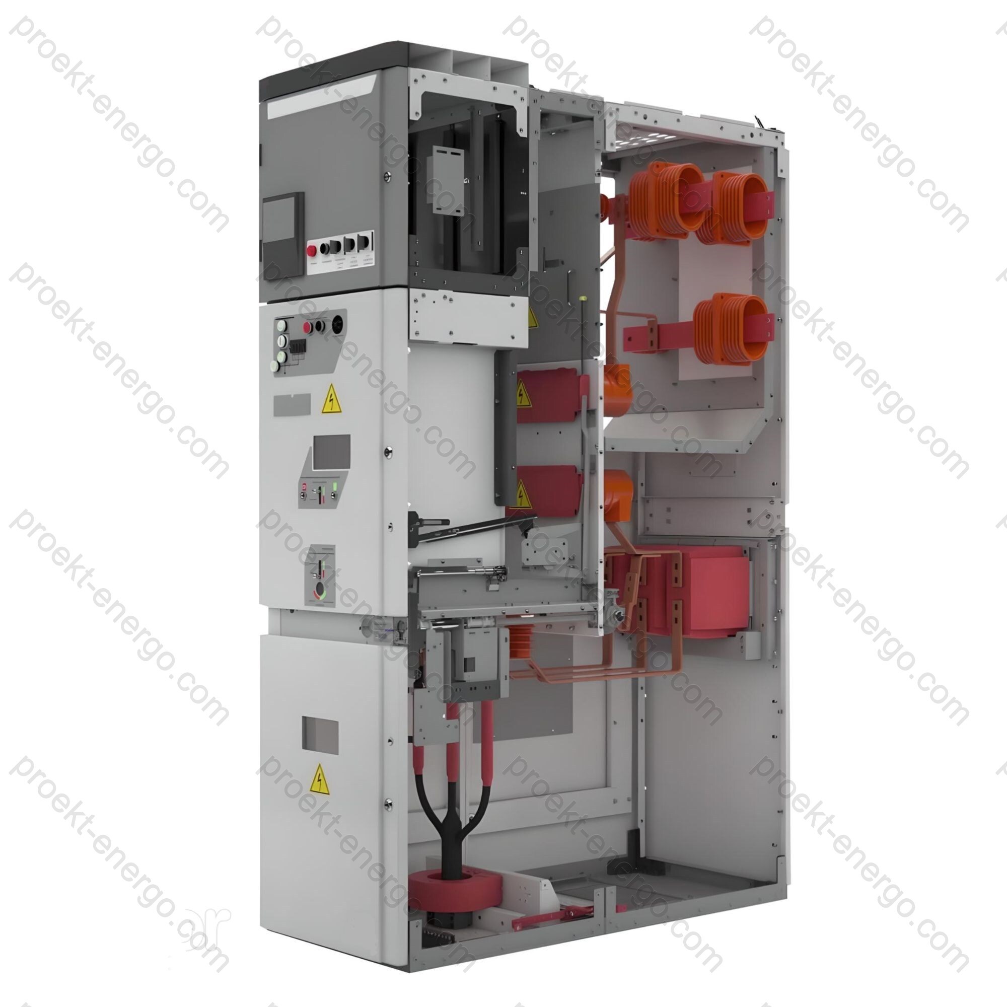
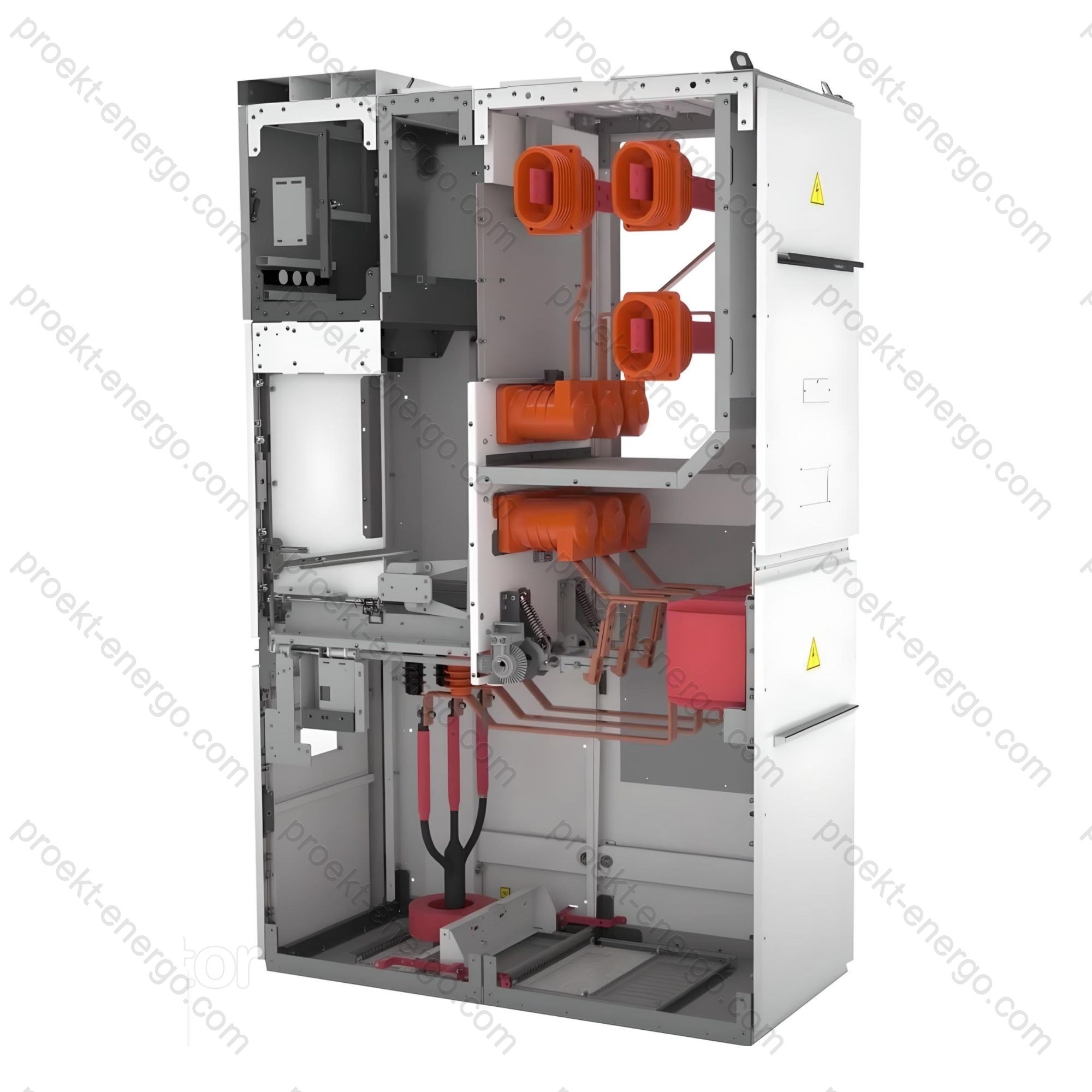
The base design is a modular enclosure made of high-rigidity galvanized steel with powder-coated facade panels. The interior is divided into independent compartments by solid steel and insulating partitions to confine any internal arc to a single volume. Busbars are arranged in the upper rear area (for the top-busbar option), the withdrawable unit (truck) is in the middle, and the cable/busbar compartment is below it or directly beneath the busbar section. This architecture increases usable termination space and enables single-sided routine operation.
Applications cover both primary and secondary distribution: KRU "Volga" is used by generating and grid companies, on industrial substations, and at municipal/utility and process-infrastructure sites. In two-row switchrooms (fronts facing), section busbars are linked by bus-duct bridges or cable jumpers (supplied on request). All current-carrying parts and metallic elements are bonded to earth per applicable standards, ensuring safe working conditions.
Service conditions for indoor installation:
- altitude up to 1000 m a.s.l. (above this-apply insulation/cooling recalculation);
- ambient temperature from -25 °C to +40 °C (room heating recommended at sub-zero temperatures);
- relative humidity up to 80 % at +15 °C; environmental conditions per EN/IEC 60721-3-3;
- non-hazardous area, free of conductive dust and aggressive gases/vapors.
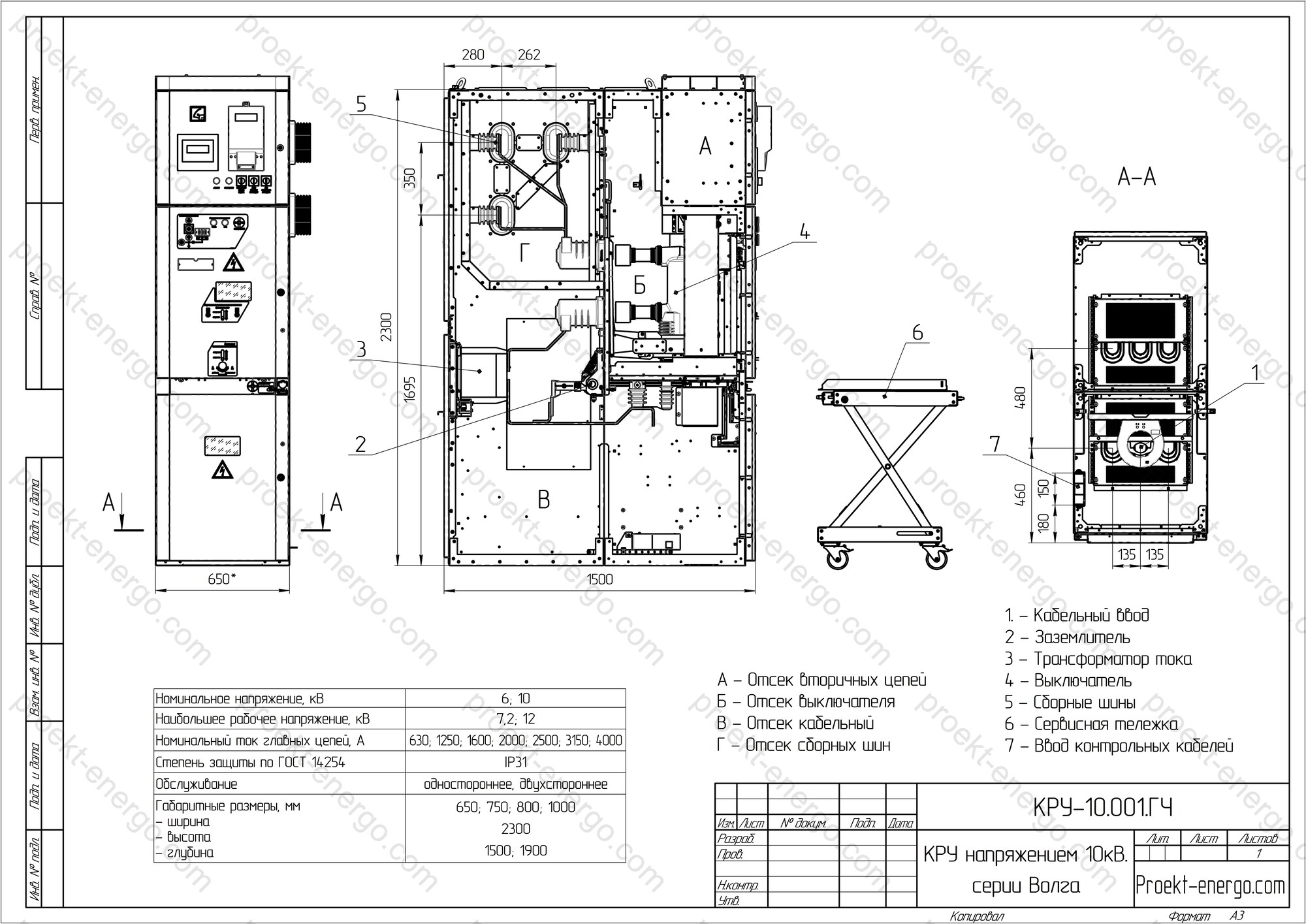
To enhance safety under arc faults, the cubicle is divided into four functional zones: cable compartment, withdrawable-unit (CB) compartment, busbar compartment, and protection/LV compartment. Each MV compartment has its own directed pressure-relief flaps.
Cable compartment. Provides space for current transformers, surge arresters, support insulators with capacitive dividers, a space heater, and, if required, a stationary or truck-mounted VT. CT secondary leads are routed directly into the LV compartment via flexible tails, avoiding service work on secondaries inside MV sections. Cable terminations are positioned at a height of at least 700 mm above floor level. Possible connections: up to three 3-core cables to 240 mm² each or up to six 1-core cables to 630 mm². A door interlock prevents opening until the earthing switch is in the Closed (earthed) position.
Withdrawable-unit (truck) compartment. Equipped with a front door featuring multi-point latching and an arc-resistant design that prevents hot-gas ejection towards the operator. Pressure is relieved via top flaps. Six bushing insulators with fixed rod contacts are mounted on the rear; a fast spring-operated earthing switch is installed externally. The shutter mechanism blocks access to fixed contacts when the truck is in the test position; shutters can be padlocked. Interlocks prevent opening the door until the truck is in test and the earthing switch is set to "Earthed." LED lighting is provided for service convenience.
Busbar compartment. Available with top or bottom busbars. With top busbars, overpressure is vented through the top flaps; with bottom busbars-via arc chutes along the lineup edges. For selective compartmentalization, busbars pass through bushing insulators (except the bottom-busbar variant). Conductors are oxygen-free copper with edge radiusing (target radius ~5 mm) to reduce field stress. Typical cross-sections: up to 1600 A - 1×10×80 mm; 2500 A - 2×10×80 mm; 3150 A - 3×10×80 mm; 4000 A - 3×10×100 mm. Controlled fastener types and torques ensure stable contact pressure in normal and fault conditions.
Protection/LV compartment. Dimensions support modern digital IEDs, metering/measurement devices, interface modules, and fiber-optic arc sensors. The door carries control keys, pilot lights, and indicators; terminal strips and auxiliaries are arranged at the bottom. Devices mount on DIN rails; an optional swing frame can be used. Anti-condensation heating with thermostat is provided; harnesses are routed in protected inter-bay raceways.
For higher automation and remote control (per spec), options include a motorized CB truck (test/service transfer), motor drive for the earthing switch (close/open), local cameras in the CB and ES compartments with feeds to the control room, contact-temperature monitoring, and a front-panel mimic diagram.
Standards compliance
- IEC 62271-1 - Common specifications for MV switchgear and controlgear;
- IEC 62271-200 - AC metal-enclosed/metal-clad switchgear up to and including 52 kV (LSC/PM, IAC classification);
- IEC 62271-100 - AC circuit-breakers; IEC 62271-102 - Earthing switches; IEC 62271-103 - Switches/load-break;
- IEC 61869-2/-3 - Instrument transformers (CTs/VTs);
- IEC 60529 - Degrees of protection (IP code);
- IEC 61000-6-2 / 61000-6-4 - EMC (industrial immunity/emissions);
- IEC 60068-2 series - Environmental/mechanical tests (as applicable).
Reliability and lifetime
- Compartmental arc containment with directed pressure relief - adjacent bays remain serviceable;
- Mechanical/electromagnetic interlocks prevent unsafe operations;
- Metallic raceways for secondary circuits - EMC robustness and service access;
- Galvanized steel with powder coating - long-term corrosion resistance.
Technical data
| Rated voltage, kV | 6; 10 |
| Highest system voltage, kV | 7.2; 12 |
| Rated current of main circuits, A | 630; 1250; 1600; 2000; 2500; 3150; 4000 |
| Rated busbar current, A | 1250; 1600; 2500; 3150; 4000 |
| Short-time withstand current (3 s), kA | 20; 25; 31.5 |
| Peak (dynamic) withstand current (1 s), kA | 51; 64; 81 |
| Service access | single-sided; double-sided |
| Insulation level (IEC 60071-1:2019) | normal |
| Environmental classification (EN/IEC 60721-3-3) | EN/IEC 60721-3-3 |
| Degree of protection (IEC 60529) | IP31 |
| Overall dimensions, mm - width - depth - height |
650; 750; 800; 1000 1500; 1900 2300 |

We offer documentation for manufacturing KRU "Volga":
Tender package. Single-line diagrams, questionnaires, and technical descriptions for procurement and feasibility review.
Working drawings & 3-D models. Layout/assembly drawings, BOM, secondary schematics, and cable schedules tailored to your production.
Contract manufacturing of assemblies. We arrange fabrication of enclosures and mechanisms with partners; you handle assembly, installation, and routine tests.
Adaptation & integration. Equivalent bays for interfacing with existing busbars/secondary circuits and third-party equipment.
Benefits of working with us:
No extra staff. Documentation is optimized for a mid-level engineer.
Fast series launch. Standardized modules and typical solutions reduce schedule and risk.
Technical support. Consulting on assembly, commissioning, and digital integration of protection/SCADA.
For additional information on KRU "Volga", contact: inbox@proekt-energo.com
Documents
PDF - Download KRU "Volga" technical information


