- We offer co-operation on replacement of old installed equipment on equipment at substations with new equipment produced at your factory. We have a large database of documentation for old, end-of-life equipment, and we will adapt your products to replace the old.

- Design of substation equipment in accordance with the technical specifications.

- Design documentation for the manufacture of electrical equipment.

- 3-D models, product drawings, BOM.

- Preparation of technical documentation for participation in tenders.

- Preparation of preliminary standards for material consumption for cost calculation..

- Consulting on projects.

..since August 1998

Proekt-Energo

Area of activity:

- Design of low-voltage, middle-voltage and high-voltage electrical equipment of substations for voltages of 0.4 - 220 kV.
- Development of working documentation in accordance with the technological capabilities of the plant.
- Preparation of preliminary technical documentation for participation in tenders for the supply of equipment.
- Consultations on project approvals.
- Supporting the production of equipment at the plant.

Specialization:

- Switchgear for indoor and outdoor installation for voltages of 6, 10, 20, 35 kV.
- Air-insulated secondary switchgears AIS for voltages 6, 10 kV.
- Complete transformer substations CTS for voltage 10 - 220 kV.
- Disconnectors for voltage 0.4 ... 220 kV.
- Drive to disconnectors.
- Replacement of withdrawable elements and switches in existing switchgear (Retrofit).
- Low-voltage switchgears for voltage 0.4 kV.
- DC 600V switchgears RU-600.

K-47 MV Switchgear  - replacement of the withdrawable element (retrofit)

Retrofit of the withdrawable element for KRU K-47 (K-47) is an engineering modernization of 6–10 kV medium-voltage metal-enclosed switchgear with replacement of worn assemblies by modern vacuum or SF6 devices while retaining the cell frame, bus bridges, cable terminations, and plant infrastructure. Key search queries: “K-47 switchgear retrofit”, “K-47 withdrawable unit replacement”, “OneFit module for K-47”, “oil CB to vacuum CB replacement”, “MV KRU/KSO 6–10 kV modernization”.

Purpose and application

The goal of the retrofit is to extend the K-47 switchgear lifecycle, increase safety and reliability, and bring the switching part in line with current norms without full replacement of the panels. Typical use cases:

  • Industrial 6–10 kV substations and distribution points at metallurgy, chemical, oil & gas processing, mining, cement and glass plants, water utilities, and municipal facilities.
  • Power supply for commercial and social facilities (malls, offices, healthcare, data centers) where downtime and CAPEX must be minimized.
  • Power for transport and infrastructure (rail hubs, airports, depots) requiring predictable interruption duty and high maintainability.

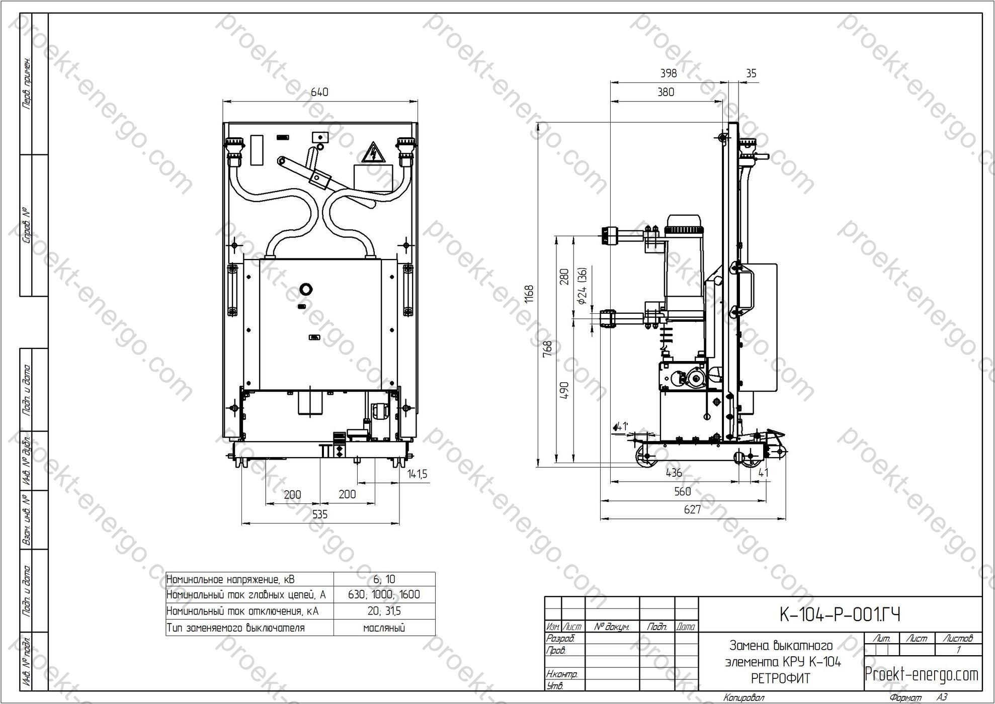
The retrofit covers replacement of an oil circuit breaker with a modern vacuum or SF6 breaker, installation of a new withdrawable unit or a factory-built modular solution, re-tuning of mechanical/electrical interlocks, shutter mechanism upgrade, adaptation of secondary circuits, replacement of the earthing switch operating mechanism, and updating nameplates/markings to common drafting rules. The result is the required short-circuit interrupting class and endurance (E2/M2), improved protection selectivity, and reduced operational risks associated with insulation ageing and oil systems.

Technical data (typical range for K-47 retrofit)

ParameterValue / rangeNotes
Rated voltage 6; 10; 12 kV (50 Hz) Per customer network (7.2/12 kV classes)
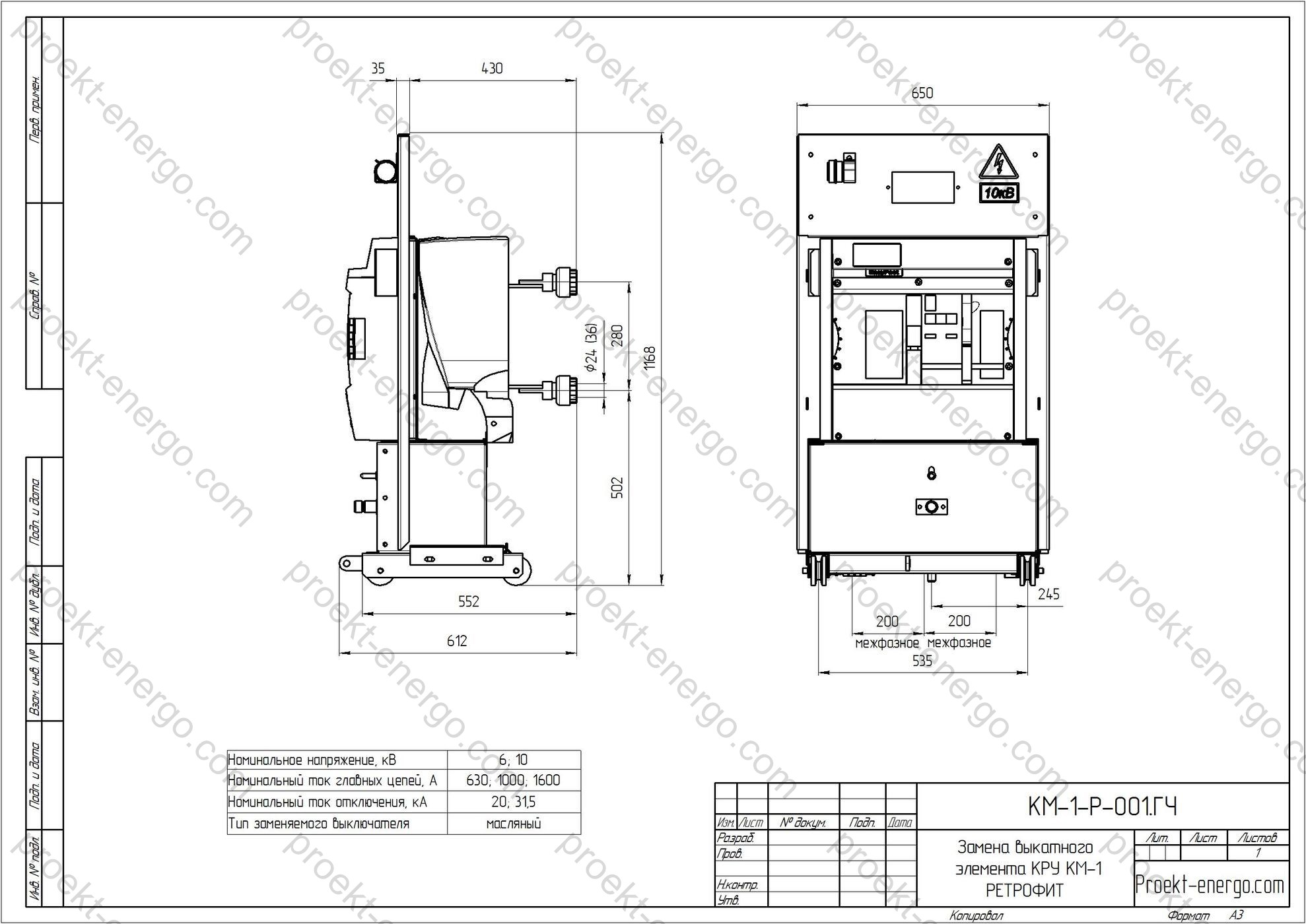
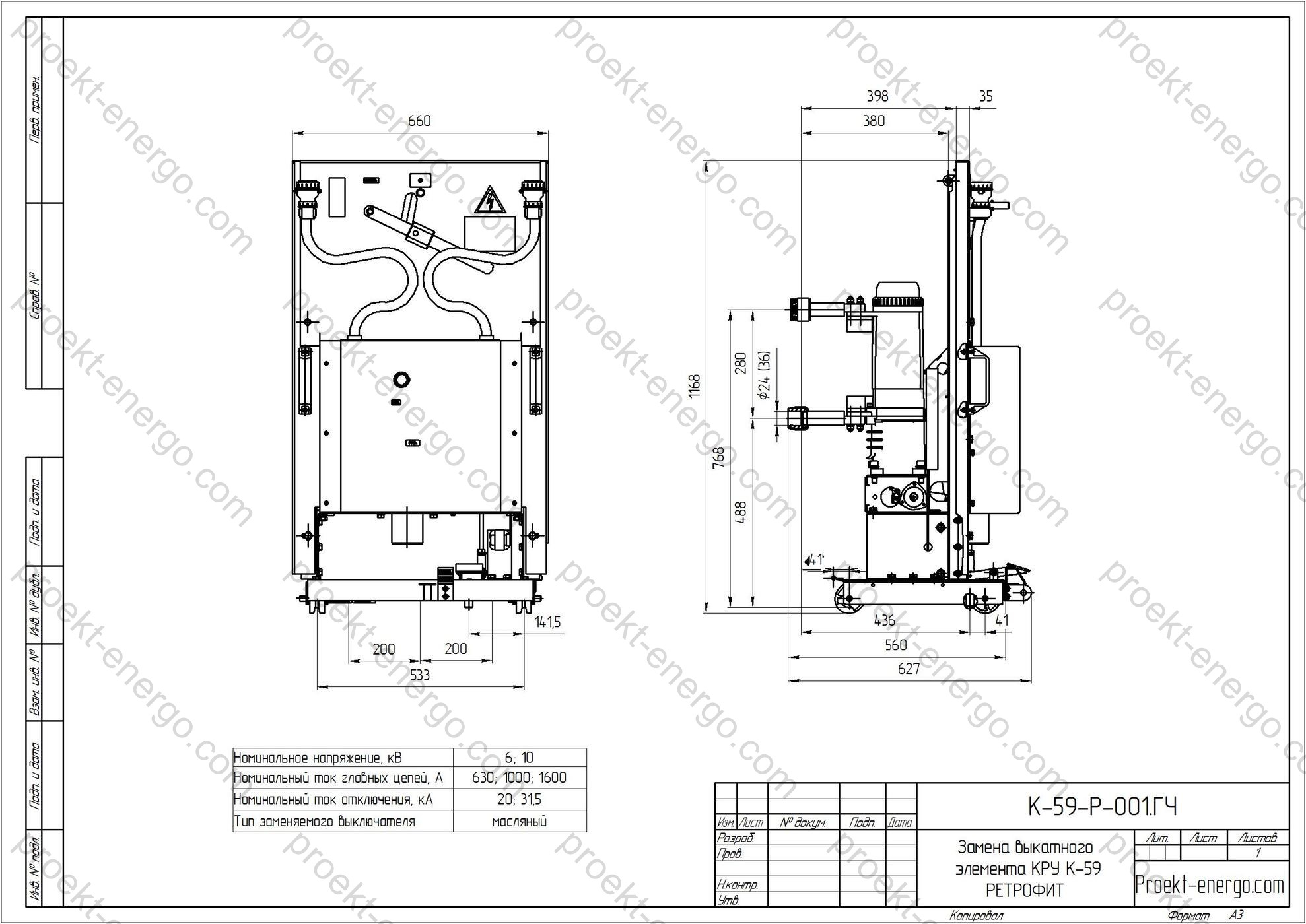
Rated continuous current 630 / 1000 / 1250 / 1600 / 2000 / 2500 / 3150 A Defined by selected breaker and busbars
Short-circuit capability (Ik) 20 / 25 / 31.5 / 40 kA r.m.s. (3 s) As per selected breaker
Peak making current (Ip) up to 50/63/80 kA Depending on configuration
Power-frequency withstand (1 min) 7.2 kV: 20 kV; 12 kV: 28 kV Phase-to-phase/phase-to-earth
Lightning impulse withstand (BIL) 7.2 kV: 60 kV; 12 kV: 75 kV Standard MV levels
Endurance class E2 / M2 Per IEC for the breaker
Enclosure degree of protection IP3X–IP4X (indoor) Per IEC 60529; higher on request
Service conditions -5…+40 °C; RH ≤ 95%; h ≤ 1000 m Special designs for severe conditions
Control circuits AC/DC 110/220 V (others on request) For drives and relay circuits
Interface Withdrawable unit plugs/terminal blocks Standard coding and labels
Options Motor operator, ATS, remote control, temperature/current monitoring Per Customer’s specification
Testing Electrical, mechanical, dielectric, interlock checks Routine + type tests (for modules)

Service conditions

The solution is intended for normal service for indoor MV switchgear: ambient -5 °C…+40 °C, relative humidity up to 95% non-condensing, altitude up to 1000 m. For other conditions (high dust/moisture, aggressive atmosphere, vibration, altitude >1000 m) the project applies special measures: tropicalization, enhanced compartment sealing, additional heaters/ventilation with thermostatic control, insulation with higher withstand and creepage, altitude correction of clearances, and anti-condensation measures (positive heat balance, dehumidifiers, operational routines). Environmental categories are assigned per EN/IEC 60721-3-3 for indoor applications (and EN/IEC 60721-3-4 if outdoor parts are involved).

Where seasonal temperature and humidity vary widely, local panel heaters with thermostats/hygrostats are used, and premises are equipped with supply/exhaust ventilation with heating and filtration to prevent corrosion, insulation ageing, and leakage-current failures. On request, microclimate monitoring (T/RH sensors, heater runtime counters) and API alarm outputs for environment threshold excursions can be provided.

Layout and design solutions

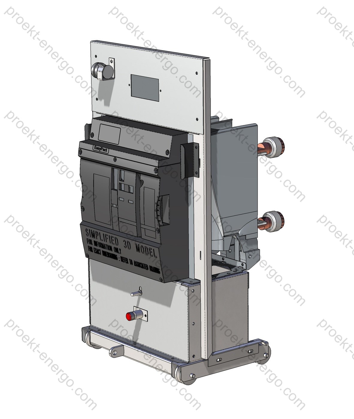
The baseline layout preserves the K-47 architecture with distinct compartments: MV withdrawable unit compartment, busbar compartment, cable/VT compartment, and secondary devices (relay panel). During the retrofit:

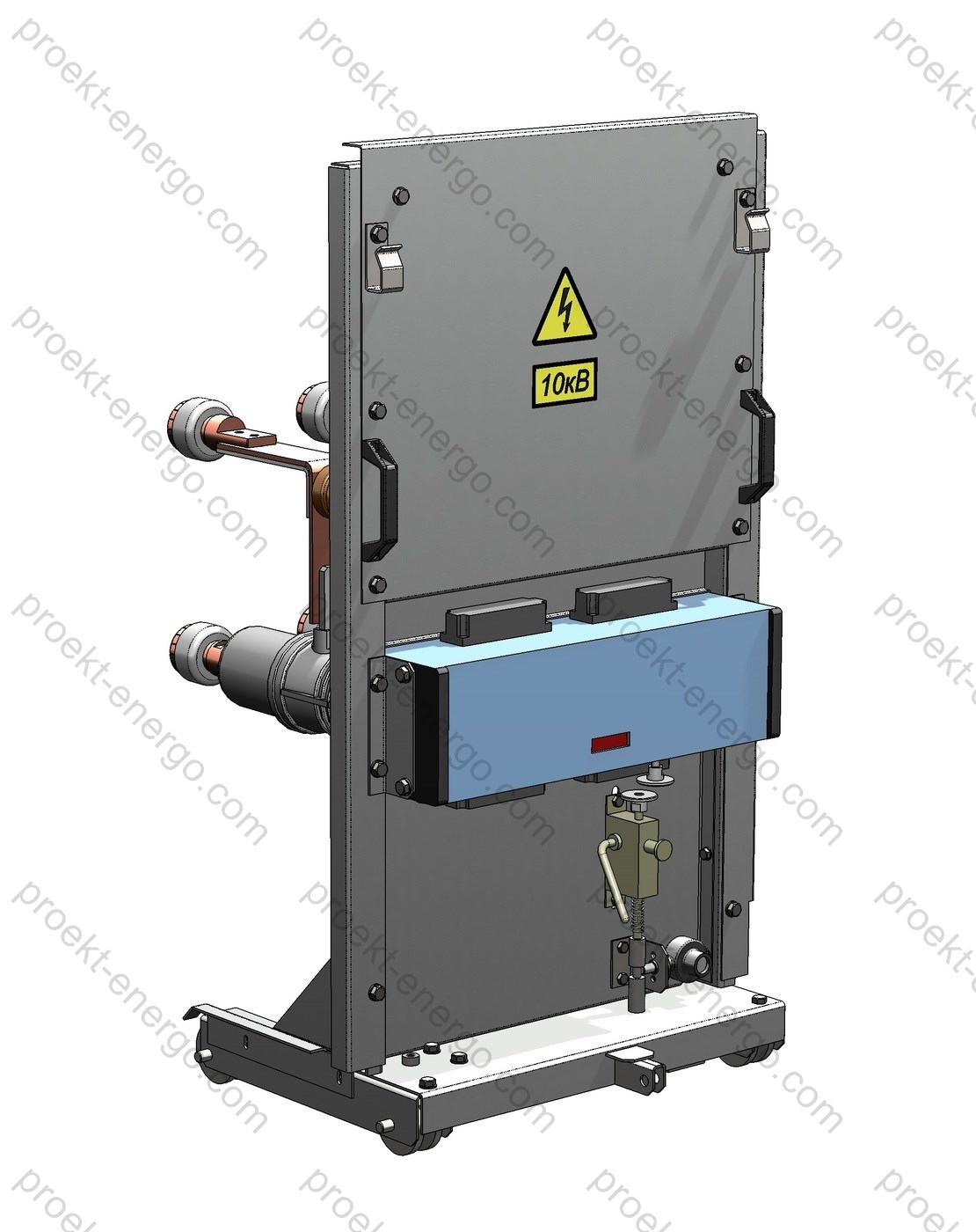
  • A new withdrawable unit (draw-out truck) compatible in interfaces and dimensions is installed with a modern vacuum or SF6 circuit breaker and spring or electromagnetic mechanism. Adaptation to existing contact systems (fixed tulip/knife contacts), guides, and latching devices is provided.
  • Mechanical interlocks are upgraded: prevention of racking with breaker ON, inhibit closing with a door open, mutual interlocks breaker/earthing switch, and door/shutter logic. If required, electromagnetic interlocks with position signalling to SCADA/DCS are implemented.
  • The shutter system (inter-phase and phase-to-earth) is renewed with improved dielectric properties; automatic shutter closing on truck withdrawal is ensured.
  • The earthing switch operating mechanism is replaced by a modern unit (manual or motor-operated) with independent locking and limit switches for remote position indication.
  • Secondary circuits are brought to contemporary practice: standard withdrawable-unit multipin connectors, DIN-rail terminal strips, unified harnesses, new position microswitches, contact-wear sensors (if supported by the device), and drive “ready” control.
  • If necessary, door reconstruction (stiffness, hinges, locks), reinforcement of inter-compartment barriers, replacement of bushings, shields, and bus supports by flame-retardant, track-resistant materials with high CTI/PTI is performed.

To unify the equipment fleet and spares logistics, devices with a broad range of current/interrupting ratings and interchangeable mechanisms are used. The design enables subsequent maintenance without dismantling the cell: draw-out, inspect, and return to service with minimal outage time.

Safety

Safety measures include comprehensive mechanical/electrical interlocking, bonding and shielding of live parts, shutter barriers, position checks of operating elements, as well as insulating guards and reinforced doors. Measures to mitigate internal arc effects are incorporated: pressure relief paths, panel reinforcement, high-strength fasteners, and hazard-zone labelling. Enclosure IP ratings are provided to meet typical indoor requirements; for abrasive dust/aggressive atmospheres, higher protection with filtered air for the secondary compartment can be applied.

The interlocking scheme prevents human error (racking IN/OUT with “ON”, closing with a shutter open, etc.). Clear indication of “OPEN/CLOSED/EARTHED” is implemented, and-on request-a coded key system enhances LOTO procedures. Integration into SCADA/DCS provides telesignals such as “READY”, “DRIVE FAULT”, and “POSITION MISMATCH”, etc.

Build options

We offer three proven retrofit configurations differing in scope, lead time, and cost:

  1. Adaptation kit for the existing withdrawable unit. A new circuit breaker is installed on the native K-47 trolley using transition plates/adapters with a kit for interlock and secondary connector modernization. Routine tests are performed. Pros: lowest material cost. Cons: higher labor and dependency on the old trolley condition.
  2. Complete replacement of the withdrawable unit. A new withdrawable unit fully compatible in geometry, contacts, and interlocks is supplied. Fast installation with virtually no work on the cell frame. The old oil-CB unit may be kept as a reserve. Balanced choice in time and risk.
  3. Factory-built plug-and-play module. A complete module with integrated breaker, shutter system, interlocks, and adapted contacts. Advantages: improved dielectric performance, type-tested to current standards, high repeatability of quality, and reduced commissioning time.
CriterionAdaptation kitNew withdrawable unitFactory-built module
Implementation time Longer (on-site fitting & testing) Short (minimal work inside the panel) Minimal (install–connect–test)
Intervention in the cell frame Local (node modernization) Not required / minimal Not required
Geometry/compatibility risks Present (depends on trolley condition) Low (new trolley) Very low (factory standardization)
Material cost Low Medium Medium / above medium
Testing On-site routine tests Routine + factory tests of the assembly Type tests of the module + routine tests

Standards compliance

The retrofit is executed in accordance with applicable standards for medium-voltage switchgear and components. Depending on the supply scope and the selected breaker, the normative base covers design, testing, interlocking, and environmental conditions. Project and O&M documents include references to applicable clauses and test protocols.

  • IEC 62271-200 - Metal-enclosed switchgear for >1 kV and ≤52 kV (requirements for MV KRU/KSO, compartment classification, internal arc, LSC/PM/PI, etc.).
  • IEC 62271-1 - Common specifications for switchgear and controlgear (normal service conditions, insulation, tests).
  • IEC 62271-100 - AC circuit-breakers (applied to the selected breaker by current and breaking ratings).
  • IEC 62271-102 - Disconnectors and earthing switches (for the earthing switch and interlocks).
  • IEC 60529 - Degrees of protection (IP Code) (enclosure ingress protection requirements).
  • IEC/TS 62271-304 - Design for severe service conditions (special climates, condensation, pollution, vibration, altitude).
  • EN/IEC 60721-3-3 / EN/IEC 60721-3-4 - Environmental classes for stationary use - indoor / outdoor (for environmental categorization, where applicable).

Engaging contractors, manufacturers, and investors

We are open to collaboration:

  • For electrical equipment manufacturers - licensable design package for local fabrication of withdrawable-unit parts, trolleys, transition plates; process sheets, routing cards, material and coating specs; consulting on commissioning and QA.
  • For installation/commissioning companies - supervision, method statements and commissioning programs, test checklists, personnel training, and author’s supervision on live MV sites.
  • For investors - scalable standard retrofit solutions (serial supply), CAPEX/OPEX reduction versus full switchgear replacement, accelerated capacity commissioning without long construction works.

Deliverable documentation

Following the survey, we provide a documentation set: inquiry sheets, 3D models (STEP/Parasolid), DWG/DXF drawings, assembly BOMs, connection & wiring diagrams, parts lists, test programs, O&M manuals, safety guide, cable schedules and terminal markings, lubrication/clearance charts, spares catalogs, and lists of compatible circuit breakers.

Advantages of working with us:

  • No need to maintain a large engineering staff: you get a complete design & instruction package suitable for an engineer of average qualification.
  • No pilot builds required: proven solutions allow serial production from the first batch.
  • Support at every stage: site survey, design, supervision, commissioning, training, author’s supervision, assistance with certification and preparation of O&M documentation.

For more information on replacing the withdrawable element of K-47 switchgear (retrofit), please contact: inbox@proekt-energo.com

PDF – Download technical information on the K-47 withdrawable-unit replacement

pdf

KM-1 Switchgear  - replacement of the withdrawable unit (retrofit)

Retrofit is the modernization or partial re-equipping of MV switchgear (KRU) and KSO by replacing physically and functionally obsolete devices with modern ones, without a full reconstruction of the switchgear room.
First of all, modernization focuses on replacing the most worn and critical component - the oil circuit-breaker. Preferred are vacuum or SF6 circuit-breakers with spring-charged or electromagnetic mechanisms that are maintenance-free, offer a high number of operating cycles, and tolerate frequent operations. A comprehensive KRU upgrade is also possible: block replacement of the compartment (withdrawable unit, shutters, earthing switch, doors, relay cabinet), as well as upgraded terminals and cable entries.
The reliability of KRU or KSO directly depends on the switching equipment. Such modernization is a simple and cost-effective way to improve availability and operational safety.
Retrofit is more economical than complete replacement, reduces the scope of design and installation works, and cuts downtime; periodic maintenance of old breakers does not guarantee reliability, while other cubicle components may not require replacement.
Typical replacement options:
Replacement of the breaker using an adaptation kit, with updated interlocks and secondary connectors; requires verification of opening time and contact pressure. The most economical, but longer and more labor-intensive option.
Replacement of the entire withdrawable unit with a new one, fully compatible in dimensions and interlocks. Fast and almost without modifications; the old truck with the oil/minimum-oil breaker can be kept as a spare.
“OneFit” - a factory module with breaker, mechanical/electrical interlocks, shutters, and an adapted contact system. Advantages:
- improved dielectric clearances and temperature control;
- type tests per IEC 62271-1/-100 (including mechanical endurance);
- high reliability of mechanisms and fewer assembly errors.

Technical data (typical)

ParameterValueComment
Rated voltage 6; 10 (up to 12) kV Depends on breaker series
Rated frequency 50 Hz 60 Hz on request
Rated continuous current 630…3150 A Frame size selected by load/busbars
Rated short-circuit breaking current 16; 20; 25; 31.5 kA 3 s, peak up to 40–80 kA
Endurance class E2/M2 (C2 - option) Per IEC 62271-100
Operating cycle O-0.3 s-CO-3 min-CO Standard sequence
Operating mechanism Spring-charged, motor-operated Manual charging - backup
Degree of enclosure protection IP31…IP41 (per design) Per IEC 60529
Service conditions -5…+40 °C, RH≤95 % No condensation; altitude ≤1000 m
Secondary control circuits 110/220 V DC; 220/380 V AC Vibration-resistant terminals
Withdrawable unit mass from 180 to 420 kg Depends on configuration
P&C interfaces IEC 61850, Modbus, Profibus By customer choice
Safety options IAC design, arc-flash sensors Per project specification

Purpose and application

The upgrade kit for the withdrawable unit of KM-1 switchgear is intended to extend the lifetime of existing medium-voltage 6–10 kV switchgear at industrial facilities, urban and rural substations, mining, oil & gas, and infrastructure sites. The main task is to replace the oil/minimum-oil breaker with a modern vacuum or SF6 circuit-breaker, integrating it into the existing mechanical and electrical architecture of the cubicle without altering the cabinet, bus bridges, cable entries, or foundation.

Retrofit is relevant when:
- failures increase due to wear of arcing contacts and seals;
- CAPEX is limited and full switchgear replacement is impractical;
- it is necessary to improve operational readiness and reduce restoration time after short-circuits;
- migrating to modern digital protection and automatic transfer schemes;
- occupational/industrial safety requires minimizing arc-flash risk and erroneous operations.

Applications include OHL/Cable line feeders, sectionalizing and line breakers, motor starters, transformer feeders, and incoming/backup lines. During the reconstruction period, a parallel approach is possible - the new withdrawable truck is installed in each cubicle in turn, reducing forced downtime.

Service conditions

KM-1 retrofit solutions are engineered for standard indoor service conditions per IEC 62271-1 for metal-enclosed switchgear:
- ambient temperature: -5 °C to +40 °C (short-term up to +45 °C);
- relative humidity up to 95 % without condensation (anti-condensation heating in the secondary and power compartments);
- installation altitude up to 1000 m ASL without derating; above this - current derating per project annex tables;
- normal/elevated pollution categories (for elevated pollution: additional sealing, moisture protection, anti-corrosion coatings);
- seismic performance per specification (travel limiters, truck latches, reinforced guides);
- enclosure protection degree: at least IP31 (external surfaces), within compartments - per cubicle design; for dusty/humid rooms IP41/54 at doors and vent filters can be provided.

Operation is permitted in systems with solidly earthed (TN) and isolated (IT) neutrals; corresponding earth-fault protections and insulation monitoring options are selected. For cold climates, heaters, thermostats, and conformal coatings for P&C boards are applied. In chemically aggressive atmospheres, additional coatings of metalwork and sealing of secondary terminals are provided.
Transport and storage - as per instructions: -25 °C to +55 °C, no condensation, stacking no more than two layers, with vibration protection.

Layout and design solutions

The modernized KM-1 withdrawable unit reproduces the mounting bases and kinematics of the standard truck, ensuring full compatibility with rails, stops, operating rods, and the shutter mechanism. Main assemblies:

  • Switching device - vacuum circuit-breaker (SF6 optional). Mechanical/electrical endurance class E2/M2, lifetime at least 10–30 thousand operations depending on series. Versions available for 6 and 10 (12) kV with breaking capacity 16–31.5 kA.
  • Operating mechanism - spring-charged motor-operated (standard) or electromagnetic; manual spring charging and remote control. Mechanical indicators “ON/OFF/CHARGED” provided.
  • Contact system - fixed “tulip” contacts and truck stabs with silver plating, adjustable contact force, and calibration pins. Geometry coordinated with KM-1 truck insertion depth.
  • Shutters and barriers - automatic shutters of the busbar and cable compartments preventing access to live parts in the withdrawn position. Non-flammable materials with arc-resistant inserts at pass-through points.
  • Interlocks - mechanical (motion recovery, earthing switch drive can be disengaged only with the truck withdrawn), electrical (position limit switches, shutter sensors), electromagnetic door locks when the breaker is ON. Inter-door key logic “key-key” for sections is available.
  • Secondary circuits - multipin connectors (Harting-type/analog) with keying, harnesses in PVC/FRLS conduit, ESKD-style marking. Standard levels 110/220 V DC, 220/380 V AC supported. Entries on vibration-resistant terminals.
  • Protection & Control - installation of digital IEDs (e.g., line/transformer/motor protection, autoreclosing/automatic transfer, event logs, oscillography). Optical arc sensors in compartments for ultra-fast tripping.
  • Chassis and guides - reinforced rollers, limiters, position latch “service/test/connected”. Handle/wrench for smooth insertion; optional screw-in mechanism.
  • Earthing switch - built-in/fixed earthing (grounding) switch in each cubicle with independent drive; interlocks prevent its closing in the “connected” position.

For projects requiring a high degree of uniformity, a modular “cradle-in-cradle” retrofit is used: a new cradle frame with device, adapted connectors, and shutters is installed into the existing compartment. This approach reduces on-site assembly labor, ensures parameter repeatability, and simplifies maintenance.

Comparison of supply/modernization options

OptionScopeInstallationAdvantagesNotes
Breaker adaptation kit New CB + brackets, linkages, interlock retuning, contact modifications Medium effort; requires contact centering and shutter adjustment Minimal CAPEX, truck retained Requires precise alignment; extended commissioning
New withdrawable unit (assembled) Truck + CB + shutter assembly + connectors; factory testing Fast commissioning; minimal in-cubicle work Reduced downtime, uniformity across the section Higher cost than adaptation kit
“Cradle-in-cradle” module (OneFit-type) New cradle frame, standard interfaces, door/lock upgrades Short installation time, plug-and-play Type-tested, improved clearances Compartment geometry survey required

Safety

The primary priority of the retrofit is personnel safety. The solution provides multiple layers: door electromagnets and limit switches, interlocks with the earthing switch drive, inter-section key systems, voltage presence indicators, and locks on drives. On request, a design with enhanced internal arc resistance (IAC) can be implemented using pressure relief ducts, panel fixation, and reinforced doors. Installing arc-flash sensors (optical/current) is recommended, enabling ultra-fast clearing (about 10–15 ms for detection + breaker time). Interlocking schemes prevent racking-in/out with the breaker ON, closing the earthing switch in the “connected” position, and accessing the power compartment with open shutters.

To improve operational safety, the following are implemented:
- P&C self-diagnostics, readiness check of mechanisms, breaker lifetime signaling;
- error-proofing: color-coded controls, pictograms, “two-hand” logic;
- temperature monitoring of bolted joints (built-in sensors/thermal tags);
- anti-condensation system (heaters + hygrostat);
- maintenance plan with inspection and lubrication schedule by operating hours and number of operations.

Manufacturing options and extras

  • Ratings: Ur 6; 10 (up to 12) kV; Ir 630, 1000, 1250, 1600, 2000, 2500, 3150 A; breaking capacity 16; 20; 25; 31.5 kA (3 s, peak up to 40–80 kA depending on breaker series).
  • Mechanisms: spring-charged motor-operated (standard), electromagnetic (per spec), with manual charging; endurance up to 30 thousand operations.
  • Protection: IEDs for lines/transformers/motors, power quality measurement, automatic transfer/autoreclosing, logs & oscillography, IEC 61850/Modbus/Profibus interfaces.
  • Instrument transformers: CTs class 5P/10P/TP (for fast tripping), VTs single-/three-phase, option for built-in sensors on the frame.
  • Climatic design: anti-corrosion coating, heaters, sealing; conformal coating of P&C boards; cold-climate execution.
  • Metering & monitoring: telemetry via Ethernet/RS-485, SCADA integration; parameter dashboards, asset lifetime reports.
  • Visual indication: mechanical flags, LED panels “Voltage Present”, “CB ON/OFF”, “Earthed”, “Truck Position”.

Standards compliance

Design and supply are performed in line with applicable international and regional standards. Depending on the scope, the following (up to six key) standards apply:

  • IEC 62271-200 - AC metal-enclosed switchgear and controlgear above 1 kV and up to 52 kV: enclosure requirements, LSC categories, partitions, internal arc (IAC).
  • IEC 62271-100 - Medium-voltage AC circuit-breakers: E2/M2/C2 classes, breaking capacities, endurance.
  • IEC 62271-1 - Common specifications, service conditions, tests.
  • IEC 62271-102 - Disconnectors and earthing switches: drive requirements, visible isolation, interlocks.
  • IEC 60529 - Degrees of protection (IP Code), applicable to doors/panels.
  • IEC 62271-304 - Guidance for severe environmental conditions (low temperatures, icing, pollution) - when specified.

Note: compliance of specific KM-1 cubicles with IAC, LSC categories, partition classes, and IP degrees is confirmed by type and/or routine tests as part of the modernized cabinet per the project test program.

Engagement with contractors, manufacturers, and investors

We are open to cooperation with mechanical engineering plants (metalwork, machining, powder coating), electrical manufacturers (harnesses, CTs/VTs, terminal assemblies), installation companies, and investors. Engagement is flexible: from supply of a complete “truck-assembled” kit to transfer of design documentation and site supervision, including staff training, P&C commissioning, and start-up support on site. For series production - we ensure unit standardization, man-hours, BOMs, process sheets, an applicability matrix for KM-1 cubicle types, and marketing support (catalogs, photo/video materials, bench tests).

Deliverables (drawings and models)

The project includes a package of design documents and 3D models: BOMs, assembly and detail drawings, secondary wiring schematics, cable schedules, parts lists, installation and O&M instructions. Formats: DWG/DXF (AutoCAD), SLDPRT/SLDASM (SolidWorks), STEP/Parasolid (exchange), PDF (plots), CSV (connection lists). On request - neutral IGES, purchased-parts lists, electrical installation cards, P&C settings tables, and test-protocol templates.


Bottom line: a KM-1 retrofit with withdrawable-unit replacement means minimal civil changes, rapid implementation, higher reliability and safety, readiness for digital P&C and monitoring systems, as well as predictable project schedule and cost.

Why work with us:

- No need to maintain highly qualified engineering staff - you receive a documentation set for the product to be manufactured, which can be handled by a mid-level engineer. 
- No need to build pilot prototypes - our experience allows you to start serial production successfully.
- Working to our documentation - your specialists will receive guidance on all nuances of replacing the withdrawable unit of KM-1 switchgear.

For additional information on replacing the withdrawable unit of KM-1 switchgear (retrofit), please contact: inbox@proekt-energo.com

PDF - Download technical information on replacement of the withdrawable unit for KM-1 switchgear

pdf

K-104 MV Switchgear – withdrawable unit replacement (retrofit)

Retrofit is an upgrade or partial re-engineering of metal-enclosed switchgear (KRU) and KSO panels by replacing life-expired components with modern devices, preserving capital investments in the existing cubicles.
The core of the upgrade is the replacement of the most wear-prone and critical component - the oil circuit-breaker. It is replaced with vacuum or SF6 circuit-breakers with spring-charged or electromagnetic operating mechanisms; compared with oil CBs, they require less routine maintenance, offer higher endurance and stable short-circuit interruption performance. A comprehensive switchgear modernization is also possible: block replacement of the compartment including the withdrawable unit (drawout truck), shutter mechanism, earthing switch operating mechanism, doors, relay compartment, as well as obsolete indicators and key interlocks.
The reliability of a KRU/KSO panel is directly defined by its switching part. This modernization is a simple and cost-effective solution that reduces failure probability and extends the service life of the switchgear assembly.
Retrofitting existing equipment is more economical than purchasing new gear, simplifies design/installation and shortens power outages; regular overhauls of oil CBs do not ensure reliability, while many cubicle assemblies can be retained.

Purpose and application

The retrofit project for the K-104 withdrawable unit is intended for rapid replacement of obsolete oil circuit-breakers with modern vacuum or SF6 devices while retaining the cubicle frame, bus bridges, cable terminations and secondary circuits. The solution applies to 6–10 kV medium-voltage switchgear at industrial enterprises, power utilities, mining, and infrastructure sites (TP, RP, GPP), as well as facilities with high continuity requirements: data centers, oil & gas, metallurgy, transport, healthcare.

Key objectives solved by the retrofit: improved electrical and fire safety; reduced operating expenses (OPEX); shorter maintenance/repair outages; alignment with current standards for insulation, breaking capacity and interlocking; integration of digital protection relays and breaker condition monitoring; flexible delivery scope - from turnkey execution to a documentation package for in-house manufacturing.

In the standard configuration the new withdrawable unit is fully compatible with mounting points, contact system (tulip/knife contacts), mechanical and electrical interlocks. To accelerate deployment, three baseline approaches are offered: adaptation of the existing withdrawable unit for a new breaker; replacement with a new withdrawable unit assembly; installation of a factory “retrofill”/“hard-bus” module (e.g., One-Fit-class solutions or equivalents) with pre-engineered interfaces and type-tested assemblies.

Technical data (typical ranges)

ParameterValue / rangeNote
Rated voltage 6; 10 kV (50/60 Hz) Defined by the existing switchgear
Rated continuous current 630–3150 A Depends on the breaker series and busbar system
Rated short-circuit breaking current 20–31.5 kA (1 s) Other ratings on request
Rated short-time / making withstand up to 50–80 kA peak Per selected breaker catalogue
Service categories E1/E2; C1/C2 For vacuum CBs (endurance / capacitive switching)
Degree of enclosure protection IP3X–IP4X (external surfaces), IP2X (service areas) Selected per installation location
Climatic operating range from -5 °C to +40 °C (24-h average ≤ +35 °C) Extended range - on request
Installation altitude ≤ 1000 m a.s.l. Higher sites require insulation re-assessment
Breaker operating mechanism Spring-charged / electromagnetic With remote control / indication
Control power supply AC/DC, 24–230 V Per project specification
Protection relay compatibility Digital IEDs, IEC 61850 (option) Migration to a process bus - on request

Service conditions

The retrofit kit is engineered for normal service conditions for air-insulated, indoor cubicles. Typical allowable conditions (aligned to medium-voltage practice): ambient temperature -5 °C to +40 °C with a 24-h average not exceeding +35 °C; relative humidity up to 95% (short-term) without condensation; altitude up to 1000 m (higher altitudes require correction of insulation clearances and test parameters); industrial pollution degree; no explosive concentrations of dust or aggressive gases; vibration within switchgear norms.
On request, versions are available for extended climates (cold, humid tropical, dusty rooms) and with enhanced condensation tolerance (additional heaters, ventilation, coatings). For seismic areas, calculations and fixings are provided to the specified intensity.

Layout and design solutions

The concept maximizes reuse of the existing K-104 cubicle metalwork and retains the standard switchgear architecture. The retrofit supply includes: a new withdrawable unit on rails with the breaker operating mechanism; adapters/transition plates for the contact system; a shutter mechanism with guides and dampers; the earthing switch operating mechanism (if mounted on the door - compatibility with the controls is ensured); a set of shutters and louvers for the truck compartment; updated locks/key interlocks; the secondary interface (terminal blocks, harnesses, connectors) with marking; a set of nameplates and warning labels.

The circuit-breaker - vacuum (preferred) or SF6 - is selected by input data: rated voltage 6/10 kV, frequency 50/60 Hz, rated current 630–3150 A, short-circuit breaking current 20–31.5 kA (higher on request), mechanical endurance, compatibility with protection schemes (electromagnetic/spring mechanisms), remote control/position indication/diagnostics options. Solutions with embedded poles are available to improve resistance to humidity and dust; modular mechanisms with reduced maintenance are possible. The withdrawable unit implements mechanical and electrical interlocks for doors/earthing switch/racking to prevent mal-operations. Main-circuit contacts are silver-bearing with spring loading, designed for repeated racking-in/out cycles and frequent engage/disengage operations.

Layout provisions include: retaining K-104 elevation marks and racking depths, adjustment of end-stops and limit switches, unified fasteners (screws, rivets, captive nuts), and reversible modernization - storing the old withdrawable unit as a spare. The shutter mechanism uses impact-resistant dielectric material with UV and ageing stability; interlock drives have service windows for inspection. For enhanced reliability, secondary circuits use spring-clamp terminals with 5.08 mm pitch; harnesses are made of heat-resistant wires with dual marking (signal and functional); all circuits are supplied with up-to-date schematics and connection tables.

Integration of modern protection and control IEDs (IEC 61850-ready, PLC/SCADA options) is performed in the existing relay compartment or in a supplied auxiliary cabinet. Options include built-in current/voltage transformers (incl. compact sensors) and temperature/partial-discharge sensors for condition monitoring. To improve dielectric performance, a barrier screen between phases and phase-to-earth is provided, along with an optimized internal airflow path.

Safety

Personnel safety is ensured by a comprehensive set of measures: mechanical and electrical interlocks, inter-door latches, key-to-key systems, forced removal of control power when switched to the test/maintenance position, earthing with a visible isolation gap, phase-to-phase and phase-to-earth barriers, protective shutters that automatically close when the unit is racked out. Correct position is verified by limit switches with panel indication. Fire-safety pictograms and EHS instructions are applied on the doors; labels indicate short-circuit categories and the IAC class where applicable to the specific solution.

To mitigate arc-flash damage, the design provides: reinforced panels in potential impact zones, pressure relief ducts, doors on heavy-duty hinges, and high-strength latching. If required, the project can include optical arc-flash sensors with high-speed tripping (via the protection IED) and arc-mitigation solutions. The degree of enclosure protection is selected per site conditions (for indoor installations typically not lower than IP3X on the external surfaces and IP2X in service areas; IP4X/IP54 for the relay-compartment doors on request). All warning signs and labels are provided in Russian with international symbols duplicated.

Manufacturing options

We offer three typical modernization scenarios. The choice depends on schedule, budget, testing requirements and the desired level of fleet unification. In practice, a mixed strategy is common: a “fast-track” start for critical feeders by installing a new withdrawable unit, followed by stepwise adaptation of the remaining ones.

OptionEssence of the solutionProsFeatures / limitations
Adaptation of the existing withdrawable unit Mounting a new breaker on the original chassis with an adaptation kit, interlock and secondary rewiring, insulation checks. Lowest cost; familiar mechanics retained; brand-flexible breaker choice. More on-site mechanical work; precise alignment required; longer duration; type testing is limited (FAT and dielectric/routine tests performed).
New withdrawable unit assembly Delivery of a new chassis with breaker, shutters, interlocks and harnesses; dimensions and interfaces compatible with K-104. Fast commissioning; minimal site work; old unit kept as a spare; easier maintenance. Slightly higher cost; requires logistics/storage.
Factory “retrofill”/“hard-bus” module (One-Fit-class / equivalent) Integrated module with implemented contact interfaces, shutters, interlocks and extended type-test program. Very short outage; improved dielectric performance; standardized maintenance; high installation repeatability. Dimensional compatibility required; fixed scope; higher price but predictable outcome.

Standards compliance

The retrofit project targets alignment of the switching part with current international/ harmonized standards. Depending on configuration and test program, the following may be applied:

  • IEC 62271-1 - common requirements for medium-voltage switchgear and controlgear (service conditions, insulation coordination, tests).
  • IEC 62271-100 - AC circuit-breakers above 1 kV (breaking classes, short-circuit parameters, test-duty cycles).
  • IEC 62271-102 - disconnectors and earthing switches (visible isolation gap, interlocks, mechanical strength).
  • IEC 62271-200 - metal-enclosed switchgear up to 52 kV (classification, compartments, internal arc classification IAC, enclosure IP).
  • IEC 60529 - degrees of protection (IP code for doors, compartments and controls).
  • For digitalization: IEC 61850 - substation communications (on request).

Contracting and partnerships

We are open to cooperation with contractors, electrical equipment manufacturers, automation integrators and investors interested in producing/localizing similar solutions. Engagement formats: licensing of the design documentation set with author support; joint pilot batch followed by serial production; OEM assembly of withdrawable units under your brand; contract manufacturing of individual assemblies (shutters, chassis, contact adapters, interlock drives). We provide manufacturing recommendations for blanks/machining, tolerance and fit charts, alignment templates, coating/painting requirements, routing sheets and QC checklists.

Documentation supplied

The documentation set is project-specific and includes: general assembly drawings of the withdrawable unit; BOMs with consumption norms; secondary wiring diagrams and cable schedules; mechanical and electrical interlock schemes; instructions for mounting/aligning the contact system; test programs and procedures (dielectric, routine, interlock verification, insulation clearances check); O&M documents (datasheet, manual, spare parts lists); 3D models and flat DXF for CAM. Formats: DWG/DXF, PDF, DOCX, XLSX; 3D - STEP/Parasolid; optionally - SolidWorks (SLDPRT/SLDASM), eDrawings.

Project stages

  1. Site survey of K-104 switchgear and collection of input data (ratings, SC currents, schematics, busbars/cables, dimensions, condition).
  2. Engineering of the withdrawable unit layout, breaker and interlock selection, agreement of a typical solution.
  3. Manufacturing of chassis/shutters/adapters, preparation of secondary harnesses, marking, QC.
  4. Factory tests of the withdrawable unit and breaker (FAT/routine dielectric, functional checks, interlock verification).
  5. Delivery / installation on site, alignment of the contact system, travel/force checks, labeling update.
  6. Commissioning, staff training, hand-over of O&M documents and spares.
  7. Service: maintenance schedule, life-cycle monitoring, supply of spares and upgrade kits.

Economics and timelines

Compared with full switchgear replacement, retrofit reduces direct CAPEX and indirect costs related to long outages, dismantling, construction work and room re-certification. In a typical project, the share of re-used assets (steelwork, busbars, cables, foundations, door assemblies) reaches 60–80% of the cost of new switchgear, directly lowering TCO. Feeder energization after delivery of the assemblies can take from a few hours to 1–2 shifts (depending on the option selected and the scope of checks).

FAQ

Can the old plug-in tulip contacts be kept? In most cases, a new set of contact clusters compatible with the K-104 busbar system is supplied, improving contact pressure stability and reducing heating.
Are the new breakers compatible with the door/earthing interlocks? Yes, interlocks are tuned to the standard kinematics and key systems; new interlock mechanisms with keys can be supplied if needed.
How are tests arranged? Factory (FAT, insulation, functional) and site acceptance tests are performed; the list and scope are per the agreed test procedure. When a factory “retrofill” is chosen, part of the checks is covered by the manufacturer’s type tests.

Why work with us

- No need to maintain a large in-house engineering team - you receive a complete documentation set for the product that can be handled by a mid-level engineer. 
- No need to build pilot prototypes - our experience enables immediate launch of serial batches.
- Working to our documentation, your team will receive consulting on all nuances of replacing the K-104 withdrawable unit.

For additional information on the K-104 withdrawable unit replacement (retrofit), please contact: inbox@proekt-energo.com

PDF - Download the technical information on the K-104 withdrawable unit replacement

pdf

K-59 Switchgear - Withdrawable Element Replacement (Retrofit)

Retrofit is the modernization or partial re-equipment of metal-clad switchgear (KRU) and KSO cubicles by replacing life-expired equipment with modern equivalents without rebuilding the switchgear room.
The primary focus is the replacement of the most stressed and safety-critical unit - the oil circuit-breaker. New interrupting devices are vacuum or SF6 circuit-breakers with spring-charged or magnetic-actuator mechanisms; unlike oil breakers, they are essentially maintenance-free, offer longer service life and stable arc-quenching characteristics. A more extensive (comprehensive) modernization of the switchgear is also possible: block replacement of the compartment, including the withdrawable element (truck), shutter mechanism, earthing switch operating mechanism, door, relay cabinet, and, if necessary, adaptation of cable terminations.
The reliability of the switchgear depends directly on the reliability of its switching equipment. Such modernization is a simple and cost-effective way to address ageing breakers in legacy switchgear and improve industrial safety.
Retrofitting existing electrical equipment is more economical than purchasing new gear, performing design and installation works for its placement, and compensating losses from reduced power delivery during replacement; at the same time, periodic repairs of end-of-life breakers do not guarantee the required supply reliability. Other cell elements do not always require renewal.

Purpose and application

The K-59 withdrawable element retrofit is intended to extend the service life of in-service medium-voltage (MV) switchgear 6–10 kV, 50 Hz at industrial plants, utility substations, and transport/municipal infrastructure. The main task is to replace obsolete small-oil/oil circuit-breakers with modern vacuum or SF6 devices with minimal intervention in the cell design and without replacing busbars, foundations, or cable entries. The solution provides:
- compliance with up-to-date safety and operational reliability requirements;
- reduced operating costs (no oil handling, less routine maintenance, predictable service intervals);
- improved maintainability thanks to shorter repair/outage windows and quick removal/installation of the withdrawable element;
- compatibility with modern microprocessor protection and control IEDs (installation of new PAC devices with self-diagnostics, disturbance recording, and communication protocols).

Typical applications include 6–35 kV incoming/feeder sections of substations, power-plant service boards, distribution substations of industrial facilities (main/plant/central distribution), mining, oil & gas, chemical, metallurgical and pulp & paper industries, as well as infrastructure power systems (airports, metros, data centers, logistics hubs). In typical projects, retrofit enables rapid restoration of interrupting capacity, achievement of required protection settings and selectivity, improved maintainability, and safer operation for personnel.

Technical data (typical values)

ParameterValue / rangeNote
Rated voltage, kV 6; 10 (up to 12 by insulation level) Selected to match the network
Rated current of main circuit, A 630 / 1000 / 1250 / 1600 / 2000 / 2500 Depends on feeder duty
Rated short-circuit breaking current, kA 20 / 25 / 31.5 (3-phase) Per IEC 62271-100
Rated short-time withstand current 1 s, kA 20–31.5 Thermal withstand
Rated peak withstand current, kA (peak) 50–80 Depends on breaker series
Circuit-breaker class E2 / M2 / C2 Switching duty, mechanical endurance, pole discrepancy
Operating mechanism Spring-charged / magnetic actuator Motor-charging option
Control voltage, V 110/220 V DC (others on request) For relays & mechanism
Degree of protection IP 2X for the compartment; higher per project Per IEC 60529
Secondary interface Standardized plug-in connector Labeling per project documentation
Mechanical endurance ≥ 10,000–30,000 operations Depends on breaker model
Ambient temperature range, °C -25…+40 (-40 on request) With space heaters as needed
P&C compatibility Modern IEDs with protocols (IEC 61850/Modbus, etc.) Per project specification

Service conditions

The solution is intended for indoor MV switchgear under the following conditions (unless specified otherwise by the project):
- ambient temperature: -25 °C to +40 °C; -40 °C available with heaters/insulation shields;
- relative humidity: up to 95 % at +25 °C without condensation; for high humidity, install cabinet heaters and desiccants in the relay cabinet;
- altitude: up to 1000 m a.s.l. (higher on agreement with dielectric clearances and/or insulation levels adjusted);
- installation category - rooms without conductive dust or aggressive gases; pollution degree according to the site category; for harsh environments, dust/moisture-protection measures are applied (door gaskets, insulating barriers, sealed entries);
- seismic withstand - as per project requirements (solutions up to 7–8 MSK/Richter available subject to calculations and/or tests).
Environmental classification is selected per IEC 60721-3-3 / IEC 60721-3-4 as applicable to the site.

Climatic execution and location category are chosen for the site conditions. For cold regions, relay-cabinet heaters and moisture protection are used; for dusty plants - reinforced shutter mechanisms, barriers, and routine inspections. Operation with equipment-induced vibration is acceptable within the limits for the corresponding class of switchgear.

Layout and design solutions

The withdrawable element is built on an adapter frame that mates the new circuit-breaker to the existing interfaces of the K-59 cell: tulip/plug-in primary contacts, busbars, shutter mechanism, and earthing-switch drive. The layout provides:
- modern circuit-breaker (vacuum or SF6) with integrated spring-charged/magnetic actuator mechanism rated to E2/M2/C2 classes and specified breaking currents;
- mechanical adaptation: guides, latches, stops, and linkages to preserve the kinematics of racking between DISCONNECTED / TEST / SERVICE (CONNECTED) positions; if required - a new racking drive with the option of motorized racking under a closed door;
- shutter mechanism with automatic closure of primary openings upon withdrawal, ensuring the required degree of protection and clearances;
- secondary adapter with a unified plug-in connector, 1:1 mapping to existing circuits, and project-based marking; migration to a new connector type is possible while keeping the cell wiring;
- earthing-switch drive (where fitted) retained or upgraded with rods and interlocks; a new fast-closing earthing switch with making capacity may be installed;
- integration of protection & control: installation of new microprocessor IEDs (ANSI/IEC functions), CTs and VTs of required accuracy classes, indication panels, and position sensors;
- “closed-door” measures: remote racking and breaker ON/OFF with the door closed, viewing windows and nameplates, addition of arc-relief channels and pressure-relief flaps (if specified by the project);
- life-cycle support: modular components, spare-parts availability, and serviceability (quick access to mechanisms, bearings, and primary contacts).

Block replacement of the compartment (frame assembly) can be provided where required - a factory-built module with the breaker, shutter assemblies, latching and interface parts adapted to the existing tulip contacts. Such a module minimizes commissioning time and provides standardized interlocks plus type-tested short-circuit withstand, dielectric and functional tests at module level.

Safety

The safety package includes standard and optional mechanical/electrical interlocks preventing incorrect operations: blocking racking with the breaker closed, blocking breaker closing in intermediate positions, blocking compartment doors with the earthing switch engaged, master-key systems, and padlockable hasps for lockout-tagout. Shutter mechanisms automatically screen live parts during withdrawal; voltage presence indicating systems VPIS/VDS, position auxiliary switches, and coded terminal blocks help prevent miswiring. On request, remote racking and remote breaker operation reduce personnel exposure to arc-flash. The design ensures required creepage and clearance distances and forms internal barriers between compartments per project category.

Manufacturing options

For K-59, multiple modernization depths are available - from replacing the breaker on the existing truck to supplying a factory-ready module. Selection depends on deadlines, budget, cell condition, and site maintenance policy. A generalized comparison is given below.

OptionScopeProsNotes / limitations
A. Breaker replacement on the existing truck Adaptation kit + new breaker; interlocks upgrade, secondary rewiring, mechanical checks Lowest material cost; familiar kinematics retained Requires fitting work and more commissioning time; depends on truck condition
B. Complete replacement of the withdrawable element New truck within K-59 dimensions, 100% compatibility with interlocks Short commissioning; old truck can remain as a spare Higher cost, lower labor; requires template fit-check
C. Factory-ready module (OneFit-type) Factory adapter frame with breaker, shutters, and interlocks Minimal outage, type-tested assemblies, higher repeatability Subject to legacy cell dimensions; verify compatibility of bushings/busbars

Standards compliance

Retrofit is performed in line with international standards for medium-voltage equipment. Typical requirements for new components and sub-assemblies:
- IEC 62271-1 - common specifications for MV/HV switchgear and controlgear;
- IEC 62271-100 - AC circuit-breakers (E/M/C classes, ratings, switching performance);
- IEC 62271-200 - metal-enclosed switchgear for indoor installation (internal partitioning/accessibility categories);
- IEC 62271-102 - earthing switches (making capacity and interlocking);
- IEC 60529 - degrees of protection (IP codes) for doors and compartments;
- IEC 60068 / IEC 62262 - environmental/impact tests for individual assemblies as per project.
The scope of routine/site acceptance tests is defined by the commissioning program and project documentation.

Contractors and partnership

We welcome cooperation with contractors, switchgear manufacturers, and investors interested in serial production and deployment of K-59 retrofit solutions and compatible MV switchgear series. Cooperation models include: supply of design documentation packages for in-house manufacturing, contract manufacturing of selected units, co-branding of ready-made modules, localization of metalwork fabrication, training and author supervision during implementation. For large-scale retrofit programs, we prepare standard solution maps, budgetary estimates, delivery schedules, and turnkey commissioning plans.

We offer documentation for the K-59 withdrawable element replacement (retrofit):

- Preliminary technical documentation for tender participation on K-59 truck replacement. We will prepare the information needed to assess manufacturability per tender requirements and data sheets.
- Working drawings, 3-D models, and other documents required to manufacture the K-59 withdrawable element at your facility. If you do not plan to make parts and assemblies yourself, we will help place orders with third-party shops. Final assembly and installation can be performed at your site.
- All documentation can be adjusted, if required, to the project requirements and to your facility’s manufacturing capabilities.
- If your substation has equipment from another manufacturer, we will prepare documentation for similar retrofit equipment to complement what is installed.

Why work with us:

- No need to maintain a large team of senior engineers - you receive a complete design package for the product that can be handled by a mid-level engineer.
- No need to build pilot prototypes - our experience allows launching serial production directly.
- Working to our documentation, your specialists will receive guidance on all nuances of K-59 withdrawable element replacement.

For additional information on K-59 withdrawable element replacement (retrofit), please contact: inbox@proekt-energo.com

PDF - Download technical information on K-59 withdrawable element replacement

pdf

  • Regulatory and technical documentation

    Regulatory and technical documentation

  • Equipment drawings

    Equipment drawings

  • Technical specifications

    Technical specifications

  • 3-D models

    3-D models

  • Equipment drawings

    Equipment drawings

  • Equipment drawings

    Equipment drawings

  • Technical specifications

    Technical specifications

  • Operating manual for equipment

    Operating manual for equipment

  • Regulatory and technical documentation

    Regulatory and technical documentation

  • 3-D models

    3-D models

  • Technical specifications

    Technical specifications

  • Operating manual for equipment

    Operating manual for equipment

  • Regulatory and technical documentation

    Regulatory and technical documentation

  • 3-D models

    3-D models

  • Operating manual for equipment

    Operating manual for equipment

Demo

FEEDBACK FORM