- We offer co-operation on replacement of old installed equipment on equipment at substations with new equipment produced at your factory. We have a large database of documentation for old, end-of-life equipment, and we will adapt your products to replace the old.

- Design of substation equipment in accordance with the technical specifications.

- Design documentation for the manufacture of electrical equipment.

- 3-D models, product drawings, BOM.

- Preparation of technical documentation for participation in tenders.

- Preparation of preliminary standards for material consumption for cost calculation..

- Consulting on projects.

..since August 1998

Proekt-Energo

Area of activity:

- Design of low-voltage, middle-voltage and high-voltage electrical equipment of substations for voltages of 0.4 - 220 kV.
- Development of working documentation in accordance with the technological capabilities of the plant.
- Preparation of preliminary technical documentation for participation in tenders for the supply of equipment.
- Consultations on project approvals.
- Supporting the production of equipment at the plant.

Specialization:

- Switchgear for indoor and outdoor installation for voltages of 6, 10, 20, 35 kV.
- Air-insulated secondary switchgears AIS for voltages 6, 10 kV.
- Complete transformer substations CTS for voltage 10 - 220 kV.
- Disconnectors for voltage 0.4 ... 220 kV.
- Drive to disconnectors.
- Replacement of withdrawable elements and switches in existing switchgear (Retrofit).
- Low-voltage switchgears for voltage 0.4 kV.
- DC 600V switchgears RU-600.

KRU K-3 (K-III) - withdrawable unit replacement (retrofit)

Retrofit is the modernization or partial re-engineering of complete switchgear assemblies (KRU) and single-sided service cubicles (KSO), replacing aged, end-of-life equipment with modern solutions while retaining existing busbars, foundations, and cable entries.
First and foremost, modernization targets the most worn and at the same time most critical component - the oil circuit-breaker. New switching devices are vacuum or SF6 circuit-breakers with spring-charged or electromagnetic operating mechanisms; unlike oil designs, they require no routine oil maintenance, offer higher interrupting and mechanical endurance (E2/M2 classes), and minimize operational risks. A more extensive (comprehensive) KRU modernization is also possible: a block replacement of the compartment, including the withdrawable unit, shutter mechanism, earthing switch operating mechanism, door, relay compartment, and, if required, current transformers and terminal blocks of the secondary circuits.
The reliability of a KRU or KSO is directly linked to the reliability of its switching devices. Such modernization is a simple and cost-effective way to address wear of legacy breakers and to improve operational safety (including internal-arc performance when upgraded to IEC 62271-200).
Retrofitting existing electrical equipment is more economical than purchasing new gear, performing design and construction works for its installation, and compensating for lost energy supply during replacement; existing cable routes are preserved. Periodic repairs and maintenance of end-of-life breakers do not guarantee supply reliability, while other cell components do not always need replacement.
Typical replacement scenarios:
Replacement of the old, end-of-life breaker on the existing withdrawable unit (KRU or KSO) with a new one using an adaptation kit, updating or replacing interlocks, and adapting the breaker’s secondary connector; additional works include alignment of plug-in contacts and verification of travels and settings. This is the most economical option but longer on site and more labor-intensive.
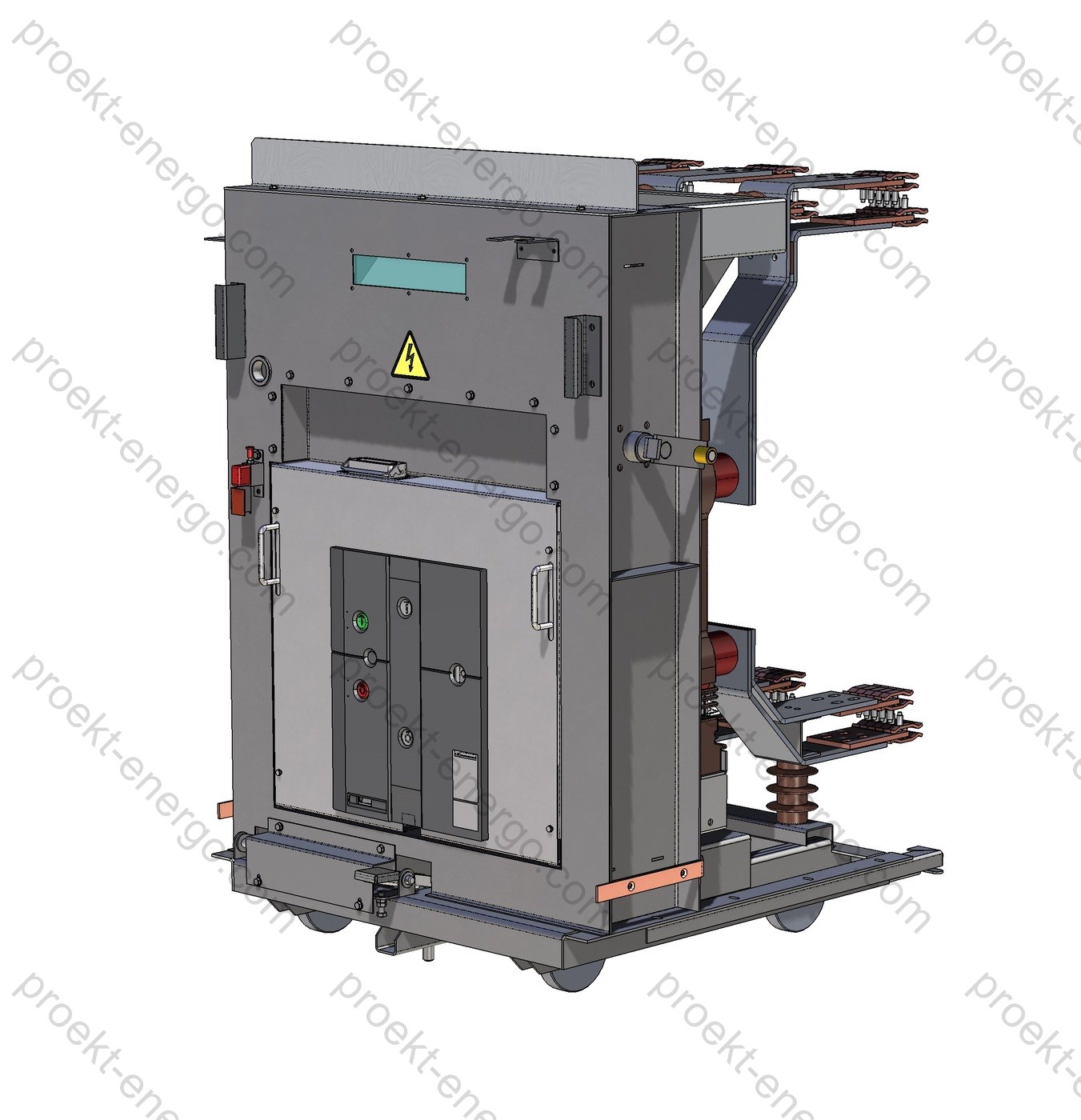
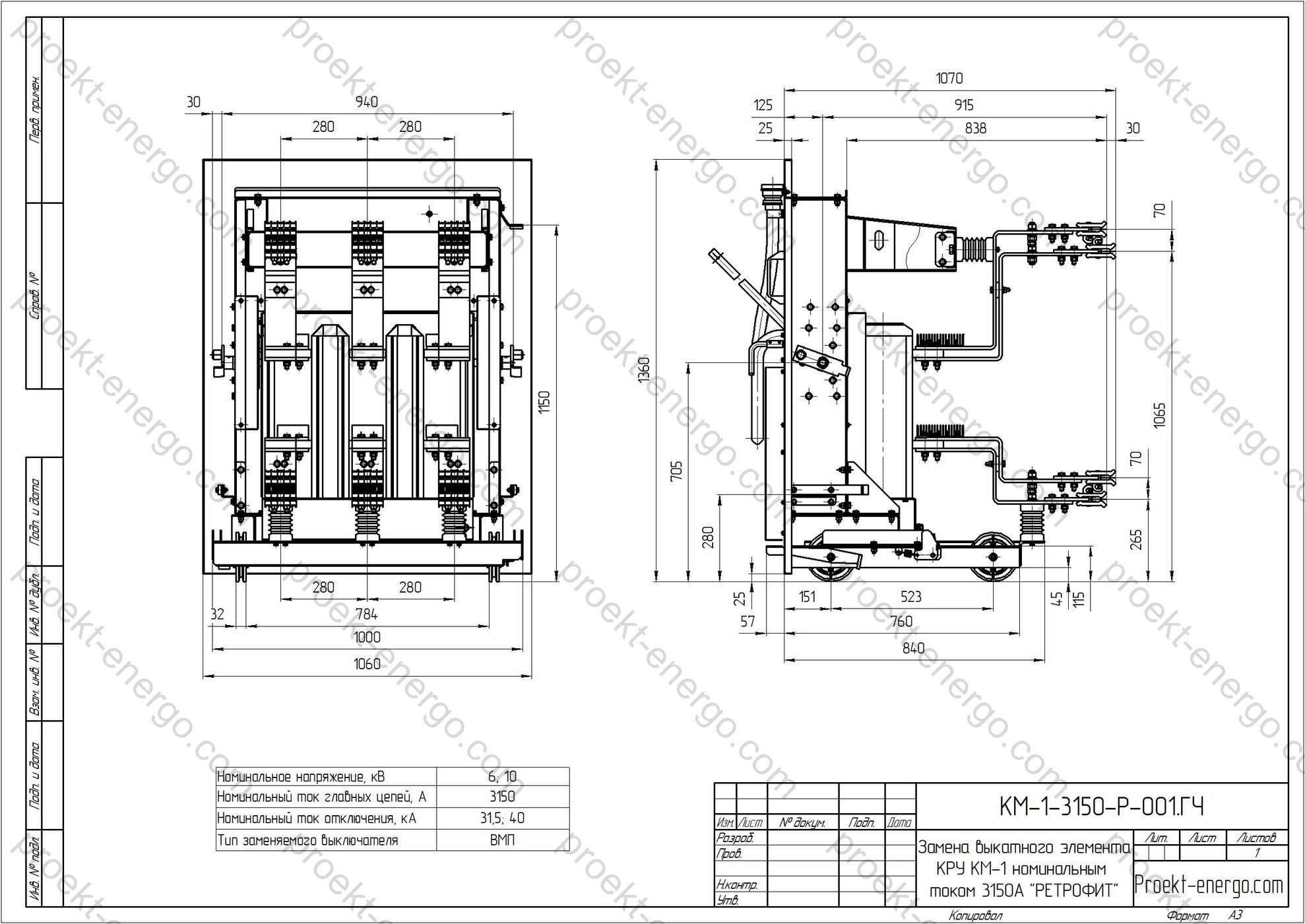
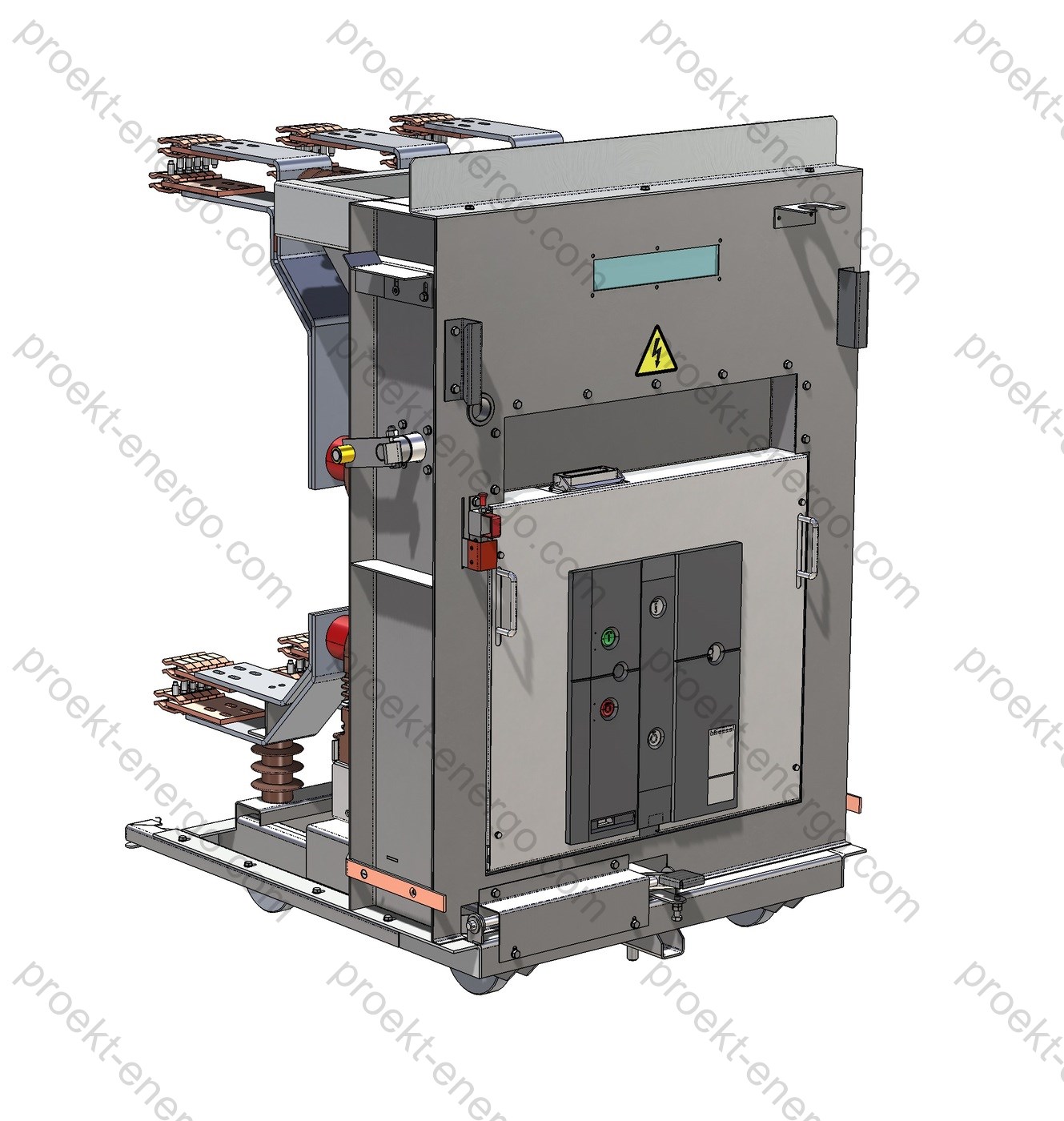
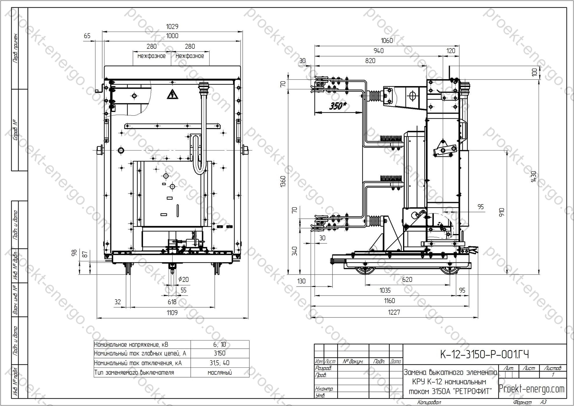
Replacement of the entire withdrawable unit together with the breaker. In this case the new withdrawable unit fully matches the dimensions and connection interfaces of the one replaced, and interlocks remain compatible; commissioning is limited to routine checks. This option is significantly faster and needs minimal on-site labor; an additional benefit is the possibility to keep the old withdrawable unit with the oil (minimum-oil) breaker as a spare.
Replacement with a factory-built module, the so-called “OneFit” - a factory-ready module with a breaker, already implemented mechanical and electrical interlocks, protective shutters, and a system adapting standard plug-in power contacts to the existing fixed parts. Advantages:
- improved dielectric performance (higher withstand levels);
- type-testing according to IEC 62271-1 and IEC 62271-100;
- increased reliability of module mechanisms and reduced internal-arc risks.

Technical data (typical range)

Rated voltage 6 or 10 kV (maximum - 7.2/12 kV)
Rated current of main circuits 630 / 1000 / 1250 / 1600 A (project-specific - up to 2000 A)
Rated short-circuit breaking current 20 / 25 / 31.5 kA
Thermal withstand current (3 s) 20 / 25 / 31.5 kA (depending on breaker model)
Peak dynamic withstand current up to 50–80 kA
Endurance class E2/M2 (lifetime up to 30 thousand mechanical operations)
Circuit-breaker mechanism Spring-charged motor-operated (standard) / electromagnetic (on request)
Auxiliary circuits 110/220 V DC; 100/220 V AC; lighting circuits 24/36 V
Enclosure degree of protection IP31/41 (typical) - project/location dependent on request
Environmental classification Per EN/IEC 60721-3-3 (indoor) / EN/IEC 60721-3-4 (outdoor), as specified in the project
Withdrawable unit overall size (reference) To suit K-3 (K-III) opening; “1:1” adaptation
Withdrawable unit mass Depends on breaker model and options (typically 150–260 kg)
Positions “Service”, “Test”, “Operate”, with indication and interlocks
Shutter system Automatic phase-bushing protective shutters
Compatibility With K-3 (K-III) guides/stops, standard earthing switch, and door

Note: exact ratings and dimensions are finalized after cell survey, measurements, and breaker model selection. For installations above 1000 m a.s.l., correction factors apply to insulation levels and currents.

Purpose and application

The new-design withdrawable unit (WU) for KRU K-3 (K-III) replaces the original unit with an oil or minimum-oil breaker and provides a modern level of switching capability and safety in medium-voltage 6(10) kV, 50 Hz distribution switchgear. Applications include distribution substations of industrial facilities, urban and rural networks, small- and mid-scale generation, mining and oil & gas, utilities, transport and infrastructure. Retrofit is effective when:

  • legacy breakers have reached end of life and repairability/spare parts cannot be ensured;
  • enhanced requirements for protection and control selectivity and reliability arise;
  • the consumer supply reliability category must be increased;
  • equipment needs to meet modern internal-arc testing and IP protection targets;
  • remote control and condition monitoring of switching devices are implemented.

Replacing the withdrawable unit preserves existing busbars, switching sections, cable entries, and foundation frames, without affecting building structures of the indoor substation. Compatibility with the existing K-3 (K-III) interlocking system and standard earthing switch is ensured, as are the unit positions “service/test/operate”.

Service conditions

The WU for K-3 (K-III) is designed for standard service conditions of 6(10) kV distribution switchgear:

  • Environmental classification: per EN/IEC 60721-3-3 (indoor; on request - EN/IEC 60721-3-4 for outdoor). Typical operating temperature ranges from -25…-40 °C to +40…+55 °C depending on selected configuration and insulation materials.
  • Altitude: up to 1000 m without derating; above this altitude, insulation and current ratings are corrected (addressed at design stage).
  • Relative humidity: up to 95 % at 25 °C without condensation; if condensation is possible, anti-condensation heaters and moisture-protection measures are provided.
  • Pollution degree: 2–3; for dusty/aggressive environments, sealing, high-durability coatings, anti-corrosion treatment, and higher IP ratings are applied.
  • Seismic withstand: up to 8 MSK-64 (up to 9 on special order) with structural verification of WU guides and retainers.
  • Overvoltage categories: compatible with surge arresters and the required impulse withstand between poles and to earth.

The WU is suitable for rooms with natural or forced ventilation. Heaters are used to prevent condensation; optional temperature and humidity sensors can be provided with signaling to SCADA upon request.

Layout and design features

The new withdrawable unit is engineered as a plug-in functional module with maximum compatibility to K-3 (K-III) guides and stops. Main assemblies:

  • Switching device - vacuum (or SF6, per project) circuit-breaker from leading manufacturers. Rated current options (630…1600 A, up to 2000 A on request) and breaking current (20…31.5 kA); E2/M2 classes; mechanical life up to 30 thousand cycles.
  • WU frame - welded, with enhanced rigidity and own guides; provides precise height/depth alignment, travel limiters, stops, and jacks for racking.
  • Plug-in contact system - adapted to existing K-3 (K-III) fixed parts. Contacts are copper-alloy with silver plating; adjustment pads and gauges are provided to verify “projection” and contact pressure.
  • Shutter mechanism - independent double-sided metal shutters close phase bushings when the WU is withdrawn; optional upgrade to separate independent “phase–earth” shutters.
  • Interlocks - mechanical and electrical interlocking devices: from key-transfer to pin coding; implemented inhibits against closing with shutters open/racking, withdrawal only with breaker open and earthing switch in “Open”.
  • Secondary connector - multipin plug (64/80/110 contacts) with coding; allows “plug-to-plug” replacement without re-soldering when migrating to modern contact ranges.
  • Operating mechanisms - spring-charged motor-operated as standard, electromagnetic optional; local/remote control, limit switches for “Test/Operate/Service” positions.
  • Insulation - support insulators from tracking-resistant epoxy compounds; interphase barriers; field-shaping screens at the front panel.
  • Options - position sensors, contact wear monitoring, operation counter, mechanism vibro-diagnostics, built-in current transformers (if needed).

Thermal design is considered: heat removal from breaker poles and contact joints is ensured; air fill factor meets calculated values; for currents ≥1250 A, the cross-section of current-carrying bars on the WU is optimized.

Retrofit options comparison

OptionScopeProsNotes/limitations
Adaptation kit for the existing WU Breaker replacement, power-contact adapters, interlock modernization, new secondary connector Lowest cost; maximum reuse of original parts Longer on site; depends on condition of old WU; more alignment work
New withdrawable unit “1:1” Full WU replacement in K-3 (K-III) envelope; interlock verification; routine functional tests Fast commissioning; minimal on-site work; old WU kept as a spare Accurate opening/guide measurements required prior to manufacture
Factory-ready module (“OneFit-like”) WU + adapter frame with implemented shutters, interlocks, contact assembly; factory type tests Higher dielectric strength; reduced internal-arc risk; shorter commissioning Highest cost; depth/projection and mass–dimension compatibility to be checked

Safety

The retrofit project includes measures to enhance electrical and mechanical safety of personnel: additional screens and interphase barriers, interlock upgrades, use of voltage presence indicators (VPIS), and integration of key-transfer locks. Upon request, the cubicle can be upgraded to internal arc classification (IAC) per IEC 62271-200, types AFL, AFLR (front/side/rear) for specified current and duration (e.g., 20–31.5 kA, 1 s) - subject to the cabinet’s structural provisions (pressure relief ducts, reinforced doors and hinges, directed pressure exhaust). The enclosure IP level follows the specification (typically IP31/41 at the front, IP2X inside the compartment with shutters closed).

Manufacturing options

The WU for K-3 (K-III) is supplied for the required currents and interrupting capabilities and accepts vacuum breakers from various brands (e.g., ABB VD4, Siemens 3AH, Schneider Electric Evolis/VA, Tavrida Electric, Eaton W-VACi, etc.) - depending on customer preference, stock availability, and regional service support. Available options:

  • Rated voltage: 6 or 10 kV (maximum 7.2/12 kV).
  • Rated main-circuit currents: 630/1000/1250/1600 A (project-specific - up to 2000 A).
  • Short-circuit breaking currents: 20/25/31.5 kA; thermal withstand up to 3 s, dynamic up to 80 kA peak (depending on breaker model).
  • Breaker operating mechanism: spring-charged motor-operated (standard), electromagnetic (on request).
  • Auxiliary circuits: 110/220 V DC, 100/220 V AC; interfaces “dry contacts”, Modbus/IEC-104 via protection & control IEDs.
  • Additional equipment: measuring CTs/VTs on the WU, temperature sensors, operation counter, position sensors, arc-flash detection (fiber-optic/pressure), etc.

Compliance with standards

Design and manufacture follow the requirements and test methods of the following (up to six most relevant) standards:

    1. IEC 62271-200 - Metal-enclosed switchgear and controlgear for >1 kV and ≤52 kV. Internal arc classification (IAC: AFL/AFLR).
    2. IEC 62271-100 - AC circuit-breakers (medium voltage).
    3. IEC 62271-102 - Disconnectors and earthing switches, including requirements for mechanisms and interlocks.
    4. IEC 62271-1 - Common specifications for medium-voltage switchgear and controlgear.
    5. IEC 60529 - Degrees of protection (IP Code).
    6. EN/IEC 60721-3-3 / EN/IEC 60721-3-4 - Environmental conditions for stationary use (indoor/outdoor).

We offer documentation for KRU K-3 (K-III) withdrawable unit replacement (retrofit):

- Preliminary technical documentation for tender participation on KRU K-3 (K-III) withdrawable unit replacement. We will prepare the information needed to assess manufacturability in line with tender requirements and inquiry sheets.
- Working drawings, 3-D models, and other documentation necessary to manufacture the KRU K-3 (K-III) withdrawable unit at your facility. If you do not plan to manufacture parts in-house, we will help source them from partner shops. Final assembly and installation can be performed at your plant.
- All documentation can be tailored to the project requirements and to your facility’s manufacturing capabilities.
- If other manufacturers’ equipment is installed at the substation, we will prepare documentation for analogous equipment to complement what is in place.

Why work with us

- No need to maintain a large in-house engineering staff - you receive a complete documentation set that can be used by a mid-level engineer. 
- No need to build prototypes - our experience allows successful launch of serial production batches.
- Working to our documentation, your team will receive consulting on all nuances of replacing the KRU K-3 (K-III) withdrawable unit.

Engaging contractors, manufacturers, and investors

We are open to cooperation with electrical OEMs, machining/assembly shops, and investors interested in manufacturing withdrawable units and modular retrofit solutions for K-3 (K-III). Possible cooperation models:

      • Manufacturing localization - production of frames, adapters, shutter mechanisms, and parts at your site to our design documentation; supply of critical assemblies (contact sets, connectors, interlocks) centrally.
      • Machining & coating subcontract - we provide 2D/3D models, process requirements, and gauges; you perform machining, welding, painting, and testing.
      • Complete “kit-to-assemble” supply - shipment of parts and assemblies; final assembly and commissioning at the end user’s site under our supervision.
      • Engineering + manufacturing - full cycle: K-3 cell survey, 3D scanning, design package, manufacturing, supervision, commissioning, and staff training.

Documentation deliverables (formats)

A full design package and supporting materials are shared with project and production teams: drawings in DWG/DXF (AutoCAD), models in STEP/Parasolid, SolidWorks assemblies, BOMs, process sheets, secondary wiring diagrams, connector pin-out tables, instructions for contact alignment and commissioning, type-test and routine-test protocols. On request - CNC files, 3D-PDF for preview, inquiry sheets, and a compatibility matrix for specific K-3 (K-III) executions.

For additional information regarding KRU K-3 (K-III) withdrawable unit replacement (retrofit), please contact: inbox@proekt-energo.com

PDF - Download technical information on K-3 (K-III) withdrawable unit replacement

pdf

KRUN K-6 (K-VI) - withdrawable unit replacement (retrofit)

Retrofit is the upgrade or partial re-equipment of metal-enclosed switchgear (KRUN) and single-sided service switchgear (KSO), replacing obsolete, end-of-life components with modern solutions.
The primary focus of modernization is the replacement of the most worn and simultaneously most critical device - the oil circuit breaker. New switching devices are modern breakers - vacuum or SF₆, with spring-stored energy or electromagnetic operating mechanisms. Unlike oil designs, they do not require regular servicing and offer significantly higher electrical and mechanical endurance. Comprehensive (extended) modernization is also possible: a modular replacement of the entire compartment, including a new withdrawable truck (draw-out unit), shutter mechanism, earthing (grounding) switch drive, door, protection & control panel, and other components.
The reliability of KRUN or KSO operation is directly determined by the reliability of its switching devices. This modernization path is a simple and economically sound way to address the wear of breakers in legacy distribution systems.
Retrofitting existing electrical equipment is financially more advantageous than purchasing new equipment, executing design and construction/installation work for its implementation, and compensating for losses caused by outages during a full replacement. Periodic maintenance of end-of-life oil breakers cannot ensure the required reliability of power supply, while the other parts of the cubicle often do not require replacement.
Equipment replacement options within a retrofit:
Replacement of the worn breaker on the existing withdrawable truck of the KRUN or KSO with a new device using an adaptation kit, refinement or replacement of interlocks, and adaptation of the breaker’s secondary plug-in connector. This is the most cost-effective option, but it requires more time and on-site labor.
Replacement of the entire withdrawable unit with breaker by a new one fully matching the dimensions and connection interfaces of the original, and fully identical in the set of interlocks. This approach is significantly faster to implement and requires minimal on-site work. An additional benefit is the possibility to keep the removed withdrawable unit with the oil (or minimum-oil) breaker as a spare.
Replacement with a factory-built “OneFit” retrofit module - a ready-to-install block with breaker, including implemented mechanical and electrical interlocks, protective shutters, and an adaptation system from standard plug-in primary contacts to the existing fixed contacts. This option is the most expensive, but it offers several advantages:
- improved dielectric performance;
- type-tested to IEC 62271-1;
- high reliability of the module’s mechanisms.

Technical data (typical values for a K-6 retrofit project)

ParameterTypical value / rangeNote
Rated voltage, kV 6 or 10 As per site network
Frequency, Hz 50/60 Compatible with protection & control
Rated continuous current of breaker, A 630–1250 (up to 1600 opt.) Depends on VCB lineup
Rated short-circuit breaking current, kA 20–31.5 Selected per project spec
Mechanical endurance, operations ≥ 10,000 For modern MV breakers
Positions “Service / Test / Disconnected” Yes With interlocking system
Breaker operating mechanism Spring-stored / electromagnetic As specified by the project
Front door ingress protection IP per project (e.g., IP31–IP54) Depends on switchgear room
Secondary circuits interface Removable multipin connector; unified to the original scheme Labeling and pinout to be agreed
K-6 dimensional compatibility Preservation of connection interfaces Adapters / frames included
Protection relays Microprocessor-based IEDs Per Client’s ToR
Testing Routine / acceptance per test program At factory and/or on site

Purpose and application

Replacement of the withdrawable unit in KRUN K-6 (K-VI) is intended for comprehensive modernization of 6–10 kV medium-voltage distribution switchgear at industrial facilities, utility substations, transport and municipal infrastructure. The retrofit provides: higher switching reliability under short-circuits and overloads; reduced operating costs; lower risks associated with oil leaks and fire hazards; longer maintenance intervals; the ability to integrate modern microprocessor-based protection, automation and control (PAC) relays, as well as to build digital control schemes and remote monitoring (SCADA/DCS). The solution applies to standard K-series withdrawable cubicles (including K-6) while retaining existing busbars, foundations, cable terminations and most inter-cubicle partitions. This approach shortens commissioning time and minimizes downtime, including staged modernization of multiple cubicles without long outages of the switchgear.

Environmental conditions

The solution is designed for indoor MV switchgear rooms with normal service conditions for medium-voltage equipment: industrial-frequency AC 50/60 Hz, rated voltages 6–10 kV, installation altitude up to 1000 m above sea level (for higher altitudes, insulation is recalculated), typical ambient temperature range per project, and standard requirements for humidity and air cleanliness in the switchgear room. Where required, additional measures are provided such as increased enclosure IP rating, anti-condensation ventilation/heaters, seismic anchoring, and adaptation of secondary circuits to local operating conditions. Environmental classes and operating conditions are specified at the questionnaire/design stage and can be aligned with EN/IEC 60721-3-3 for stationary indoor installations and EN/IEC 60721-3-4 for stationary outdoor conditions, depending on project requirements.

Layout and design solutions

The baseline configuration of the withdrawable unit for KRUN K-6 includes: a modern breaker (vacuum/SF₆) on a standardized carriage; adapters for primary plug-in contacts matching the fixed parts of the cubicle; a new shutter mechanism and mechanical interlocks preventing incorrect operations; a modernized earthing (grounding) switch drive with a visual position indicator; a front door with viewing window, key interlocks and a new set of position sensors; a secondary plug-in connector panel/cassette matching the native K-series scheme; current and voltage transformers where replacement is required; sets of flexible/rigid bars for connections; intermediate cabling for adapting metering and PAC circuits; dust- and moisture-protective covers and seals. The withdrawable design ensures precise positioning in “Service / Test / Disconnected” with guides and latching assemblies rated for multiple racking cycles.
Vacuum breakers with spring-stored or electromagnetic mechanisms are preferred, offering high electrical/mechanical endurance, low operating costs and environmental safety. Compatibility with SF₆ breakers of the appropriate class is maintained if required by the project or fleet standardization. The mechanical layout allows installation of devices with varying dimensions provided tolerances for connection interfaces and pole spacing are met.

Safety

Personnel and equipment safety is achieved by a set of measures: mechanical and electrical interlocks exclude racking the withdrawable unit when the breaker is closed; the shutter mechanism automatically covers primary contact windows when the unit is moved to the test/disconnected position; visual position indicators and key interlocks ensure intentional operation; the earthing (grounding) switch is equipped with an independent drive and an interlock preventing erroneous closing onto live parts. Additionally, modernization of protection and automation is provided (replacement of electromechanical relays with microprocessor-based IEDs featuring measurements, fault recording and remote control). Materials and insulating parts are selected to meet flame resistance and tracking resistance requirements, and the enclosures ensure the specified IP degree for the intended service conditions.

Manufacturing options

Three typical modernization options are offered:
1) Breaker adaptation kit - installation of a new breaker on the existing withdrawable truck using transition frames, with modernization of interlocks and secondary plug-ins. Minimal capital cost, but precise supervision and adjustments are required on site.
2) New withdrawable unit in K-6 dimensions - a fully assembled withdrawable unit identical in connection interfaces and interlocks, enabling a plug-in replacement with minimal downtime. The removed unit can be retained as a spare.
3) Modular retrofit (“OneFit / OneFit-analog”) - a factory-built block with type tests, pre-installed interlocks and shutters, unified interfaces and full adaptation to the fixed parts of the cubicle. Maximum deployment speed, improved dielectric characteristics and factory-verified functionality.

CriterionAdaptation kitNew withdrawable unitModular retrofit
Implementation time Medium (depends on required rework) Short Minimal
Cost Low Medium High
On-site work volume Elevated Low Minimal
Type testing of the assembly On site Factory / on site Factory type-tested
Geometric accuracy demands to cubicle High Medium Medium / low
Breaker selection flexibility High High High (within module range)

Compliance with standards

KRUN K-6 (K-VI) retrofit solutions are engineered and manufactured in line with applicable regulations for medium-voltage equipment. The scope of supply and the test program consider the requirements of, among others:
- IEC 62271-1 (general requirements for medium-voltage switchgear and controlgear);
- IEC 62271-100 (AC circuit breakers);
- IEC 62271-200 (metal-enclosed switchgear, AC, above 1 kV up to 52 kV);
- IEC 62271-102 (disconnectors and earthing switches);
- IEC 60529 (degrees of protection - IP code);
- Where necessary - national and industry standards, as well as environmental classes and service conditions per project documentation (e.g., EN/IEC 60721-3-3 for stationary indoor, EN/IEC 60721-3-4 for stationary outdoor).

Engaging contractors, manufacturers and investors

We are open to cooperation with manufacturing facilities and investors interested in producing withdrawable units and adaptation kits for KRUN K-6 retrofits. A partnership model is offered: licensing of detailed design documentation, training of technologists and installation personnel, supply of assemblies and critical components, author supervision and incoming quality control. For contractors, templates of manufacturing and test procedures (FAT/SAT), checklists and acceptance criteria are available, together with support during customer audits and operation. This enables rapid ramp-up of serial production and consistent product quality.

Deliverable documentation (drawings, 3D models)

The documentation package for the K-6 withdrawable-unit retrofit includes: questionnaires; preliminary technical documents for tenders; complete manufacturing drawings (DWG/DXF), 3D models (STEP/Parasolid), SolidWorks assemblies, bills of materials and purchased-parts lists; single-line and schematic diagrams; routing sheets and assembly/adjustment instructions; test programs and procedures; typical implementation projects; operation and maintenance manuals. Documentation is adapted to the project requirements and the manufacturing capabilities of your facility. Where needed, we provide nameplate/label templates, recommended spares lists and guidance on sourcing breakers, mechanisms and instrumentation.

We offer documentation for the replacement (retrofit) of the KRUN K-6 (K-VI) withdrawable unit:

- Preliminary technical documentation for participation in tenders related to the replacement of the K-6 (K-VI) withdrawable unit. We will prepare the information required to evaluate manufacturability in line with tender requirements and questionnaires.
- Working drawings, 3-D models and other necessary documentation to manufacture the KRUN K-6 (K-VI) withdrawable unit at your facility. If you do not plan to produce parts in-house, we will help source them from subcontractors. Final assembly and wiring can be carried out at your facility.
- All documentation can be adjusted, if required, to match the project requirements and your facility’s process capabilities.
- If different manufacturers’ equipment is installed at the substation, we will prepare documentation for manufacturing compatible units to complement the installed base.

Benefits of working with us:

- No need to maintain highly specialized engineering staff - you receive a documentation set for the product that can be used by a mid-level engineer.
- No need to build pilot prototypes - our experience allows successful launch of serial batches.
- Working to our documentation, your team will receive consultation on all nuances of replacing the KRUN K-6 (K-VI) withdrawable unit.

For additional information on the KRUN K-6 (K-VI) withdrawable unit replacement (retrofit), please contact: inbox@proekt-energo.com

PDF - Download technical information on K-6 (K-VI) withdrawable unit replacement

pdf

KRU K-37 - withdrawable unit replacement (retrofit)

RETROFIT is a modernization or partial re-equipment of complete switchgear (KRU) and single-sided service switchgear cubicles (KSO) by replacing life-expired equipment with contemporary solutions. For a range of 6–10 kV substations and switchgear, the best effect is often achieved by replacing the most worn and at the same time most critical component - the oil (low-oil) circuit breaker - with a vacuum (or SF6) circuit breaker with spring-stored energy or electromagnetic operating mechanism. Unlike oil devices, modern breakers do not require routine oil management, provide higher switching endurance, and simplify operation. In parallel, as needed, interlocks, shutters, earthing-switch drives, secondary circuits, and door panels are upgraded. Retrofit preserves busbars, foundations, cable entries, and mounting interfaces, cutting budget and downtime without compromising reliability.

Purpose and application

The proposed solution replaces the withdrawable unit (WU) of KRU series K-37 with a new WU compatible in overall dimensions and connection interfaces with the existing cubicle. The solution applies to 6 and 10 kV, 50 Hz medium-voltage switchgear at power plants, utility substations, industrial and infrastructure sites, as well as agricultural and extractive facilities. Retrofit may be performed either to maintain serviceability of existing cubicles when breaker life is exhausted or as part of programs to improve operational safety, reduce O&M costs, and digitalize secondary systems.

The upgraded withdrawable unit with a modern circuit breaker supports normal switching operations (close/open, automatic reclosing, protection and control) under normal and faulted network conditions, including short circuits and overloads. The design is suitable for networks with isolated or compensated neutral. Thanks to standardized primary contact adapters and a compatible secondary plug, full electromechanical compatibility is ensured with most K-37 variants without modifying the busbar compartment or cable terminations. In some cases, modernization is complemented by new current/voltage transformers, arc-flash protection, modern P&C relays, and condition-monitoring sensors.

Technical data (typical)

ParameterValue for K-37 retrofitNote
Rated voltage 6 kV / 10 kV Frequency 50 Hz
Highest operating voltage 7.2 kV / 12 kV Per selected breaker type
Rated continuous current of main circuits 630 / 1000 / 1600 A (by agreement up to 2000–2500 A) Thermal evaluation per project
Rated short-circuit breaking current 20 / 25 / 31.5 kA Depending on breaker frame size
Short-time withstand current (3 s) 20 / 31.5 kA Typical duration 3 s (main circuits)
Peak withstand current (amplitude) up to 51–80 kA Depends on cubicle configuration
Breaker endurance class class M2/E2 Per norms for vacuum circuit breakers
Degree of protection IP31/IP34 (indoor); up to IP54 (outdoor) As per project and base cubicle
Environmental classification EN/IEC 60721-3-3 / EN/IEC 60721-3-4 Per project requirements
Control circuit supply 110/220 V AC/DC Other options on request
WU overall size (approx.) compatible with K-37 (width 900/1350 mm; depth up to 1600 mm) No change to mounting interfaces
Secondary interface compatible plug/adapter strips Executed to existing schematics
Trolley positions service / test / connected Movement and closing interlocks
Options arc-flash protection, sensors, operation counters, remote monitoring SCADA integration

Operating conditions

The retrofit kit is intended for operation in indoor switchgear rooms and/or outdoor cabinets that meet applicable regulations. Environmental classes - EN/IEC 60721-3-3 / EN/IEC 60721-3-4 (per project); ambient temperature typically from -40 … -45 °C to +40 … +45 °C; relative humidity up to 95 % with anti-condensation measures (heaters, ventilation, drain channels). Permissible installation altitude - up to 1000 m a.s.l. without derating; for higher altitudes, dielectric and thermal calculations are performed additionally. Degree of enclosure protection for “indoor” execution - not less than IP31/IP34; for “outdoor, insulated” execution - up to IP54 (per project). In high-condensation and polluted environments (e.g., pump rooms, chemical plants, coastal areas), measures are provided for insulation classification and protection, anti-condensation heating, and microclimate control.

Seismic resistance, vibration strength, fire resistance of cable entries, and categories for pollution/condensation are selected according to the original K-37 cubicle data and project requirements. For outdoor cabinets additionally specified: insulation package, roof/canopy design, cable glands, UV-resistant coatings, and corrosion protection of structures and fasteners (hot-dip galvanizing, powder coatings).

Layout and design solutions

The baseline layout of the new withdrawable unit for K-37 retains the original logic: trolley (frame) with circuit breaker, primary plug-in contacts, racking mechanism along guides, a set of mechanical and electrical interlocks, shutter mechanism, mating part of the secondary connector, and operator controls on the front panel. The design uses:

  • a modern vacuum (or SF6, per project) circuit breaker with spring-stored energy or electromagnetic mechanism, endurance class E2/M2 per current norms;
  • primary-contact adapters providing geometric compatibility with the K-37 busbar and cable fixed parts without buswork modification;
  • a universal secondary connector (or adapter strip set) for connection of existing control, indication, and protection circuits;
  • a feeder earthing-switch mechanism (if provided by the cubicle design) with operating handle, interlocks, and position indication;
  • shutter devices that automatically close the primary sockets when the trolley is withdrawn, and door mechanical interlock;
  • a kit of nameplates, pictograms, viewing windows, and inter-bay/inter-compartment interlocking devices (per project).

Three modernization levels are available for typical K-37 modifications (by effort and implementation time):

  1. Adapter kit for the existing WU - breaker replacement and adaptation of interlocks/secondary circuits on the stock trolley. Lowest cost, but higher labor and duration; precise adjustment required.
  2. Complete replacement of the withdrawable unit - supply of a new WU assembly fully compatible in mounting, dimensions, and interlock logic. Fastest commissioning; the original oil-breaker WU may be retained as a spare.
  3. Modular “plug-in” block (factory retrofit module) - an integrated readiness module with built-in shutters, interface frame, standardized contacting system, and interlocks. Maximum unification and improved clearances; fastest installation; higher initial cost.

Following site survey and review of the as-built documentation, the optimal option is selected. If required, the front panel is revised, new mating parts of the secondary connector are installed, limit switches and internal panels are replaced/relocated. The design accounts for CT/VT locations, cable window sizes, service areas, and accessibility of operating mechanisms.

Safety

The retrofit concept maintains or improves the operational safety level compared to the original K-37 configuration. Mechanical and electrical interlocks prevent mal-operations (no WU movement with breaker closed, no closing with shutters open, breaker–earthing-switch interlock, door interlock with feeder energized). Fixed positions “service/test/connected” are provided, with position indicators for main devices, provisions for sealing and hasps for padlocks. On request, arc-flash protection systems (optical sensors/current criteria) and microclimate monitoring/event logging devices can be applied.

For cubicles with higher personnel-safety requirements, solutions can be engineered in line with modern principles of internal arc classification (IAC) and LSC categories for service continuity. In existing cubicles, the degree of conformity is determined by the enclosure design, gas exhaust, pressure-relief flaps, and reinforced doors. During retrofit, additional exhaust ducts and reinforced body elements may be installed (based on calculations and tests).

Manufacturing options and features

  • Circuit breakers: vacuum types from industrial manufacturers (ratings 6/10 kV; currents 630–1600 A; by agreement up to 2000/2500 A; breaking capacity 20–31.5 kA); alternatively, specified SF6 breaker series.
  • Operating mechanisms: spring-charged motor operators (with emergency manual charging) or electromagnetic; manual operating handle for earthing switch; local/remote control available.
  • Secondary circuits: secondary connector compatible with the original scheme; adapters for existing harnesses; upgrades to AR/ATS schemes, tele-signals, and local indication.
  • Protection & services: protection and control relays (instantaneous/delayed overcurrent, earth-fault, directional stages, breaker-failure protection), arc-flash protection, recorders, integration via IEC 61850/Modbus (per project).
  • Materials & execution: galvanized or stainless parts, powder coatings, anti-condensation heaters, temperature/humidity sensors.
  • Documentation: 3D models, design drawings, BOMs, installation/commissioning/operation manuals, check protocols, and test procedures.

Comparison of typical retrofit approaches

ApproachScopeAdvantagesConsiderations
Adapter kit for stock WU Breaker replacement, interlock rework, secondary adaptation Lowest price, trolley retained Precise alignment, longer commissioning
New WU assembly Supply of trolley with breaker, shutters, connector, and interlocks Fast commissioning, minimal installation work; old WU may remain as spare Higher cost than adapter kit
“Plug-in” factory module Single readiness block with interface frame and standardized contacts Shortest schedule, improved clearances, factory testing Highest initial cost, but lowest risks and lead time

Standards compliance

The retrofit solution is engineered in accordance with current requirements for medium-voltage switching devices and metal-enclosed switchgear. The project specifies applicable standards and boundaries of responsibility (device/WU/cubicle). When selecting the breaker and accessories, the following documents are considered (the list is refined for a specific site):

  • IEC 62271-1 - Common specifications for medium-voltage switchgear and controlgear;
  • IEC 62271-100 - AC circuit-breakers (endurance classes, breaking capability, tests);
  • IEC 62271-102 - Disconnectors and earthing switches (mechanical requirements and interlocks);
  • IEC 62271-200 - Metal-enclosed switchgear 1–52 kV (LSC/IAC classification for new/modernized cubicles);
  • IEC TS 62271-304 - Guidance for operation under condensation/pollution in indoor environments;
  • EN/IEC 60721-3-3 and EN/IEC 60721-3-4 - Environmental condition classes for stationary use (weather-protected / non-weather-protected).

Partnering with manufacturers and contractors

We welcome cooperation with electrical OEMs, machine-building plants, and engineering firms for series production of withdrawable units for K-37. Possible formats: supply of a complete WU set under the customer’s nameplate, supply of “semi-finished” assemblies (frames, adapters, front panels, shutter mechanisms), delivery of a design package with author support during production start-up, as well as turn-key projects - design, manufacturing, commissioning, and site energization. For investors and integrators, entering the service market for the installed base of KRU K-37 and related series (K-V, K-VI, K-IX, etc.) is attractive with minimal R&D thanks to ready-made typical solutions, libraries of 3D models, and established process charts.

Documentation offered

The typical package includes: working drawings (DWG/DXF), bills of materials, operation documentation, 3D models (STEP/Parasolid), front-panel layouts, assembly schematics and incoming inspection sheets, transport/storage/installation/commissioning instructions, type and routine test protocols. Documentation is adapted to tender requirements and your production capabilities (sheet metal thicknesses, available coatings, fastener range, etc.). Upon agreement, editable sources for AutoCAD/SolidWorks/Compass-3D are provided for quick PLM integration.

We offer documentation for replacement of the withdrawable unit in KRU K-37 (retrofit):

- Preliminary technical documentation for tenders to replace the withdrawable unit in KRU K-37. We will prepare the information you need to assess manufacturability to meet tender requirements and questionnaires.
- Working drawings, 3-D models, and other necessary documentation to manufacture the K-37 withdrawable unit at your facility. If you do not plan to manufacture parts and assemblies in-house, we will help outsource fabrication. Final assembly and wiring will be performed at your site.
- All documentation is adjusted, if necessary, to project requirements and to your plant’s manufacturing capabilities.
- If other manufacturers’ equipment is installed at the substation, we will prepare documentation for analogous equipment to supplement the installed base.

Benefits of working with us:

- No need to maintain a highly specialized engineering staff - you receive a complete documentation set; an engineer of average qualification can work with it. 
- No need to build pilot prototypes - our experience enables successful launch of serial production batches.
- Working to our documentation, your specialists will receive consultation on all nuances of replacing the withdrawable unit in KRU K-37.

For additional information on replacing the withdrawable unit in KRU K-37 (retrofit), please contact: inbox@proekt-energo.com

PDF - Download technical information on K-37 replacement

pdf

KR U KM-1 rated current 3150 A - withdrawable unit replacement (retrofit)

Retrofit is the modernization or partial re-equipping of MV switchgear (KRU/KSO) by replacing life-expired devices with modern solutions without a full replacement of switchboards and bus systems.
First of all, the upgrade targets the most stressed and critical component - the oil circuit-breaker. It is replaced with a modern vacuum or SF₆ circuit-breaker with a spring-charged or electromagnetic mechanism; unlike oil breakers, these do not require routine oil/contact overhauls, provide higher switching endurance, and have predictable maintenance intervals. A comprehensive switchgear upgrade is also possible: block replacement of the compartment including the withdrawable unit (truck), shutter mechanism, earthing-switch drive, doors, relay cabinet, as well as modernization of the secondary protection/control circuits (migration to microprocessor-based relays).
The reliability of KRU or KSO is directly determined by the condition of its switching apparatus. Such modernization is a straightforward and economical way to compensate for wear of breakers in legacy distribution gear and to bring operation in line with current safety requirements. Retrofitting existing electrical equipment is more cost-effective than purchasing new gear, does not require large-scale construction/installation works, and reduces losses from forced downtime; periodic repairs on old breakers do not ensure the required level of availability. Other cell elements, if in satisfactory condition, can remain in service.

Purpose and application

Replacing the withdrawable unit in KM-1 switchgear with a rated current of 3150 A is intended to restore lifecycle and increase operational reliability of medium-voltage distribution systems in industrial, utility, energy, municipal and infrastructure networks. The solution targets bus-section and bus-tie cubicles, incoming/feeder cubicles with elevated current loads, supplies for large motor loads (pump stations, compressor and ventilation units, mills), as well as panels with frequent operations (auto-reclosing/automatic transfer - AR/ATS).

Retrofit is applied during reconstruction of 6–10 kV substations (adaptation to other voltage levels is possible as per project), modernization of main and distribution switchboards, within industrial revamping programs, for mines and pits, transport-infrastructure upgrades, and when migrating distribution equipment to modern requirements for reliability, electrical safety, and condition-based diagnostics.

Typical use cases: replacement of oil circuit-breakers with exhausted service life; migration to vacuum breakers with high electrical/mechanical endurance classes; fleet unification of breakers and mechanisms; introduction of microprocessor-based protection and monitoring; reduction of operating costs and improvement of energy efficiency by lowering technical losses.

Technical data (typical)

ParameterValue/RangeNote
Rated current of withdrawable unit 3150 A 2500/4000 A configurable by project
Rated voltage 6 or 10 kV Other levels - on request
Frequency 50 Hz 60 Hz - on request
Rated short-circuit breaking current up to 31.5 kA Depends on the selected breaker
Endurance class (IEC) E2/M2 Electrical/mechanical endurance
Opening (trip) time ≤ 60–80 ms Depends on operating mechanism
Degree of protection (enclosure) IP3X–IP4X For indoor installations
Interlocking system Mechanical + electrical Prevents incorrect operations
Mechanical endurance 10,000–30,000 operations Per breaker manufacturer’s data
Operating mechanism type Spring-charged / electromagnetic With self-monitoring circuits
Interrupting medium Vacuum / SF₆ (for certain options) Selection per specification
Temperature rise at contact joints Within allowable limits Verified by heat-run tests
Condition monitoring/diagnostics Option Temperature sensors, operation counters, communication interfaces
Mass of the withdrawable unit From 120 kg Depends on configuration
Manufacturing lead time from 4–8 weeks Clarified per current production load

Note: values are typical and are refined for a specific project depending on the chosen breaker model, short-circuit levels, and environmental/climatic execution.

Service conditions

The withdrawable unit supplied within the retrofit project is designed for service conditions typical of 6–10 kV indoor MV switchgear: ambient temperature from -10…-5 °C to +40…+45 °C (the exact range is confirmed by project and breaker type), relative humidity up to 80–90% at +20 °C without condensation, installation altitude up to 1000 m a.s.l. (dielectric-strength correction factors apply above this). Operation is permitted in environments free of chemically active gases, conductive dust, and explosive mixtures. Vibration severity - normal for indoor switchgear; elevated vibration is agreed additionally. Housekeeping and cleanliness shall meet applicable O&M practices for medium-voltage switchgear.

The degree of protection of panels and doors generally conforms to IP codes for indoor installations (e.g., IP3X/IP4X for the enclosure and IP2X in secondary-circuit areas). The retrofit does not degrade the original dust/moisture protection; if required, the project provides new seals, additional barriers, shutters, and ventilation filters, as well as versions for increased humidity and dust. For rooms with condensation, space heaters and their control by thermostat/hygrostat are provided.

Layout and design solutions

The withdrawable unit for KM-1 3150 A is engineered to fit existing overall and interface dimensions, retaining the geometry of power contact fingers, centerline heights, insertion stroke, and interlock kinematics. Depending on the chosen modernization strategy, the following configurations are used:

  • Adaptation kit for the existing withdrawable unit. Includes power-contact adapters, transition plates, new feeders and busbars, rework of latching points, restoration of dielectric clearances, replacement of secondary plugs/connectors, and overhaul of the running gear. Contact pressure is adjusted; checks include contact resistance and temperature-rise, and verification of open/close travel.
  • Full replacement of the withdrawable unit. A new “cartridge” is manufactured with a factory-installed vacuum or SF₆ breaker, integrated shutters, interlock elements, and mechanical position indication. The design replicates mounting points and avoids any welding on the cell body.
  • Factory “block-in-block” module (typical One-Fit-class solutions). A frame module with integrated adapters, metering/measurement transformers or sensors as per project, diagnostics modules, an upgraded shutter mechanism, and an interface for microprocessor protection terminals. The package shortens commissioning time and improves fleet uniformity.

The support frame and current-carrying parts are made of copper bars with silver/tin plating and non-flammable spacers that maintain stable contact pressure. To exclude local overheating, adjustable clamps are used together with additional guides and stops to prevent skewing during racking-in/out. Insulating spacers are made of GFRP/DPK with high creepage distances; edges and radii are coordinated with requirements for dielectric strength and partial discharges.

Secondary circuits are modernized for contemporary protection/control terminals (analog/digital inputs, digital outputs, communication interfaces). Where required, “plug-in” connectors are provided to speed up removal, with labeled harnesses, terminal blocks, interlock relays, and local/remote-control schemes. Interlocking logic is programmed: blocking racking-in with earthing switch closed, blocking closing with shutters open, door interlocks, mutual interlocks with bus-section cubicles, etc.

The shutter mechanism safely isolates the main busbars when the truck is withdrawn and prevents access to live parts; viewing windows and position indicators are provided. The earthing-switch mechanism is manual or motor-operated, with limit switches, mechanical/electrical interlocks, and “Earthed/Disconnected” indication.

Safety

The retrofit project is oriented toward compliance with modern electrical-safety requirements and arc-fault protection practices. The layout and interlocks preclude personnel misoperations; safe-access service zones are provided. Modern circuit-breakers are used with higher switching endurance, fast opening times, built-in self-monitoring, and the ability to diagnose mechanism and contact-system condition. Integration of arc-flash protection (optical/fiber or sensor-based), temperature sensors on bolted joints, event loggers, and network interfaces for SCADA is available by project.

Design measures maintain dielectric clearances and creepage distances, shield secondary circuits from fault currents, and provide systematic bonding/earthing of metal parts and doors. At the Customer’s request, infrared thermography is performed after commissioning and during trial operation, as well as power-frequency and/or VHF withstand tests in accordance with the test program.

Manufacturing and delivery options

  • Supply of an adaptation kit to install a new-type breaker on the existing withdrawable unit: transition plates, power adapters, installation kit, modernization scheme, and alignment worksheet.
  • Supply of a new withdrawable unit “turn-key”: assembled truck, installed breaker, shutters, interlocks, connectors, spare-parts kit; only minimal panel rework required.
  • Supply of a factory “frame module”: a standardized solution with extended diagnostics and a pre-validated set of interlocks and interfaces.
Retrofit optionImplementation timeOn-site work scopeApprox. costPros/Features
Adaptation kit for existing withdrawable unit Medium High (alignment, setup) Minimal Maximum reuse of existing parts; flexible for non-standard cells
New withdrawable unit Short Low Medium Series assembly, fast replacement, predictable result
“Block-in-block” frame module Short Low Above medium Built-in diagnostics, standardized solutions, minimized risks and downtime

Standards compliance

The retrofit is oriented to the applicable requirements for medium-voltage switchgear and switching devices. The most relevant standards used in design and supply:

  1. IEC/EN 62271-200 - metal-enclosed AC switchgear 1…52 kV (design rules, type tests, internal arc performance).
  2. IEC/EN 62271-100 - AC circuit-breakers (rated duties, mechanical/electrical endurance, duty cycles).
  3. IEC/EN 62271-102 - disconnectors and earthing switches (mechanics, interlocks, making/withstand of earthing switches).
  4. IEC 62271-1 - common specifications for high-voltage switchgear and controlgear (nameplate data, marking, climatic allowances).
  5. IEC 60529 - degrees of protection (IP code) for enclosures, indoor.
  6. (As applicable) IEC/EN 61869 - instrument transformers; IEC/EN 60255 - protection relays and automation.

Engagement of contractors and partners

We invite electrical-equipment manufacturers, metalworking production sites, and investors interested in serial production of retrofit kits for withdrawable units for KM-1 3150 A switchgear. The partnership model provides licensed transfer of the complete set of working documentation, process charts, routing sheets, and BOM/cutting lists, personnel training, support for initial series, as well as co-branding and service support at the place of operation. Contractors can perform machining, plating, painting, subassembly, and electrical testing - with subsequent shipment of completed trucks to the Customer or to our consolidation warehouse.

Documentation offered

We provide a complete documentation package for tenders and manufacturing:

  • Preliminary package: technical proposal, questionnaires, list of applied equipment, 3D visualizations, consolidated cost and lead-time estimate.
  • Working documentation: general views, assembly drawings, parts lists, lists of purchased items, single-line and schematic diagrams, wiring diagrams, interlock and control-logic schemes.
  • Manufacturing models: 3D (STEP/Parasolid), 2D (DWG/DXF), process sketches, inspection cards, list of normative docs; formats: AutoCAD, SolidWorks, Parasolid, DXF, DWG.
  • Operation documentation: user manuals, installation & maintenance instructions, procedures for contact-pressure alignment, Poka-Yoke checklists for switching operations, test programs & methods, FAT protocols, and commissioning checklists.

Project stages

  1. Survey of the existing KM-1 cubicle, measurement of baseline dimensions, photo documentation of assemblies, retrieval of electrical diagrams.
  2. Design of the adaptation kit/new truck, 3D-model approval, release of working documentation.
  3. Manufacturing, factory tests, quality control, packing.
  4. Delivery to site, dismantling/installation, alignment, connection of secondary circuits.
  5. Commissioning, verification of interlocks, functional and electrical tests.
  6. Personnel training, handover of operation documentation, support during the warranty period.

Economic efficiency

Retrofit can reduce CAPEX by 40–70% compared to full switchgear replacement, shorten downtime, shift part of the work to shop conditions, and lower OPEX by eliminating oil-system servicing and routine overhauls of legacy mechanisms. Additional benefits include higher equipment availability, shorter restoration time after faults, and the introduction of predictive-maintenance tools.

FAQ

Can the existing busbars/leads be retained? In most cases - yes, provided contact surfaces are restored and thermal performance is confirmed. Overheated/loosened joints detected during survey are replaced.

What about protection relays? At the Customer’s request, secondary circuits are migrated to microprocessor-based terminals with remote monitoring, event logging, settings management, and self-diagnostics.

Are construction works required? As a rule, no. The “no modification to the cell body” concept minimizes construction/installation works; if the enclosure is heavily worn, local replacement of doors/fascia elements is possible.

We offer documentation for the replacement of the withdrawable unit of KM-1 3150 A switchgear (retrofit):

- Preliminary technical documentation for participating in tenders for replacement of the withdrawable unit of KM-1 3150 A switchgear. We will prepare the information you need to assess manufacturability in line with tender requirements and questionnaires.
- Working drawings, 3-D models, and other necessary documentation to manufacture the withdrawable unit of KM-1 3150 A switchgear at your facility. If you do not plan to fabricate parts in-house, we will help place orders at partner shops. Your plant will perform final assembly and installation.
- All documentation, where necessary, is adjusted to project requirements and to your facility’s technological capabilities.
- If other manufacturers’ equipment is installed at the substation, we will prepare documentation for producing compatible equivalent equipment in addition to the installed base.

Advantages of working with us:

- No need to maintain a large team of highly qualified design engineers - you receive a documentation set for the product that can be used by a mid-level engineer. 
- No need to build prototypes - our experience allows launching serial production successfully from the start.
- Working to our documentation - your specialists will receive consultation on all nuances of replacing the withdrawable unit of KM-1 3150 A switchgear.

For additional information on replacement of the withdrawable unit of KM-1 3150 A switchgear (retrofit), please contact: inbox@proekt-energo.com

PDF - Download technical information on replacement of the withdrawable unit of KM-1 3150 A switchgear

pdf

K-12 (K-XII) switchgear rated 3150 A - withdrawable unit replacement (retrofit)

Retrofit is a technologically and economically efficient way to extend service life and improve the reliability of medium-voltage metal-clad switchgear (KRU) and single-front cubicles (KSO) without replacing the cubicle frame or busbar systems. For KRU K-12 (K-XII) rated 3150 A, modernization means replacing the oil circuit breaker with a modern vacuum or SF6 circuit breaker, installing a new withdrawable unit (truck) with adaptation of the plug-in primary contacts, upgrading interlocks and secondary connectors, and-if required-updating the shutter mechanism, earthing switch, and protection relay compartment. This approach shortens outages, reduces operational risk and maintenance costs, and brings the protection scheme up to current practice.

Purpose and application

The K-12 (K-XII) retrofit is intended for distribution of electrical energy in medium-voltage 6(10) kV networks at substations of utilities and industrial plants. The solution applies to incoming and bus-section cubicles, feeders to cable lines and power transformers, auxiliary services of power plants, and facilities in the oil & gas, mining & metallurgical, chemical, transport infrastructure, and water supply sectors. Replacement of the withdrawable unit and circuit breaker is relevant when:

  • the oil breaker has exhausted its lifetime and failures increase due to ageing of insulation and mechanics;
  • short-circuit levels have risen after network reconfiguration or installation of higher-power transformers;
  • the substation is migrating to digital protection & control IEDs with fast, selective tripping requirements;
  • there is a need to lower operating costs (eliminating oil handling, periodic overhauls, leaks, and disposal).

Our modernization preserves the overall and mounting dimensions of the K-12 switchgear, does not require foundation changes, new cable entries, or bus-duct rearrangement. Where needed, a block replacement of the withdrawable unit compartment with doors and mechanisms is performed-especially useful when guides and mechanical interlocks are worn.

Technical data (typical range)

ParameterValue / rangeNote
Rated voltage 6 / 10 kV (50 Hz) Depends on cubicle and network
Rated continuous current (main circuit) up to 3150 A Temperature-rise verification per test procedure
Rated short-circuit breaking current 31.5 / 40 kA Per selected breaker (per specification)
Short-time withstand current (1–3 s) 31.5 / 40 kA (1–3 s) Thermal withstand of main circuit
Peak withstand current up to 80 / 100 kA peak Depends on apparatus class
Breaker endurance class E2 / M2 Switching and mechanical endurance
Operating mechanism Spring-charged motor / magnetic actuator With remote control circuits
Earthing (grounding) switch Manual / motor-operated Full set of interlocks
Front door protection degree IP31…IP41 (front) Selected per service conditions
Current/voltage transformers Classes 5P/10P/PX, 0.2S/0.5 Per IEC 61869-2/-3
Protection & control IEDs Microprocessor-based, with event logs Modbus, IEC 60870-5-104; IEC 61850 optional
Service conditions -5…+40 °C, RH ≤95%, H ≤1000 m Special conditions by agreement
Service life 20+ years with scheduled maintenance Breaker endurance ≥10 000 operations

Service conditions

The solution targets standard service conditions for medium-voltage switchgear: ambient air temperature -5 °C to +40 °C (24-h average ≤ +35 °C), installation altitude up to 1000 m a.s.l., relative humidity up to 95% without condensation, normal pollution and vibration levels indoors. For “harsh” environments the following variants are available:

  • cold climate (-25…-45 °C): anti-condensation heaters, moisture-proof gaskets, adjusted greases and insulation materials;
  • high altitude (>1000 m): adapted creepage/clearances and/or reduced insulation levels by design studies;
  • high humidity and dust: higher IP rating of front doors, sealed entries, anti-corrosion coating of metalwork;
  • seismic, marine, tropical executions-subject to separate agreement with type-test evidence or calculations.

For KRU with 3150 A, special attention is paid to thermal performance and ventilation of the front section: we verify temperature rise of current-carrying parts, contact pairs, and busbar take-offs (thermal chamber/IR thermography during commissioning) and, if needed, increase the cross-section of flexible connectors and use silver-plated contact surfaces with controlled contact pressure.

Layout and design

The updated withdrawable unit (truck) for K-12 is engineered as a drop-in solution: it reproduces baseline mounting dimensions and travel logic, as well as the interface with shutters, earthing switch, and inter-section interlocks. Main assemblies:

  • Circuit breaker - vacuum (preferred for 6–10 kV) or SF6, with spring-charged motor or magnetic actuator. Endurance class E2/M2, high breaking capacity (typically 31.5/40 kA), lifetime ≥10 000 O-C cycles.
  • Plug-in contact adapter - mates new primary contacts to the busbar and cable stabs of the K-12 cubicle; guide geometry and stop positions are preserved to ensure “test”, “isolated”, and “service” positions.
  • Mechanical interlocks - truck latching block, door and key interlocks (Kirk/Castell), interlock against closing when withdrawn, earthing-switch and shutter interlocks.
  • Secondary connectors - standardized 24/32-pin blocks with adapters to existing harnesses; project-specific replacement with modern multi-pin coded connectors is available.
  • Earthing switch - manual or motor-operated, with electrical/mechanical interlocks and position indication, rated for feeder short-circuit duties, bonded to the cubicle earthing system.
  • Shutter mechanism - upgraded for auto-closing when the truck is withdrawn, preventing access to live parts and foreign object ingress.
  • Relay compartment - installation of modern protection & control IEDs (reclosing, ATS, logic schemes), embedded metering modules, and communication interfaces (Modbus RTU/TCP, IEC 60870-5-104, IEC 61850 if a gateway is provided).

On request, a modular “OneFit” retrofit kit is implemented integrating the withdrawable frame, mechanical interlocks, and contact assemblies-this accelerates installation and reduces site works. For cubicles with very short outage windows, factory pre-assembly and FAT can be performed with subsequent installation on site during a planned window.

Safety

Personnel safety is paramount for K-12 retrofits. The design provides:

  • a complete set of mechanical interlocks and a clear operating sequence (withdraw/insert truck, close/open, earth);
  • primary-contact shutters preventing access when the truck is withdrawn;
  • position indication of devices and truck, duplicated by auxiliary contacts for protection & signalling;
  • option to install arc-flash protection (optical sensors + ultra-fast trip) and powered racking (remote insert/withdraw) to reduce arc-flash risk;
  • execution that respects the cubicle’s pressure relief paths and venting-retrofit does not degrade factory internal-arc withstand and, with a comprehensive door upgrade, can improve operator front-zone safety.

Build options and modernization approaches

For a specific K-12 cubicle we offer three base scenarios with predictable lead time and cost:

OptionScope of workImpact on switchgearTestingWhen to choose
Adaptation kit on the existing truck New breaker, adapter plates, contact adapters, interlock upgrade, secondary connectors Minimal intervention; original truck retained Site commissioning, secondary checks, temperature-rise, on-site making/breaking checks Limited budget; long adjustment window available
New withdrawable unit “turnkey” Completely new truck with breaker and interlocks, spares kit Moderate intervention; better ergonomics; mechanisms with zero wear Factory and routine tests; on-site commissioning Fast return to service; fleet standardization is important
Modular OneFit Factory-ready module: frame, contacts, interlocks, shutters; integrated with the existing cubicle Minimal site works; high repeatability of quality Module type/routine tests + on-site commissioning Minimal outage and predictable result required

Standards compliance

Design and testing follow applicable standards for medium-voltage equipment. For K-12 retrofits the most relevant are:

    1. IEC 62271-200 - Metal-enclosed switchgear 1…52 kV: design, type and routine tests, internal-arc classes.
    2. IEC 62271-100 - AC circuit-breakers: breaking performance, endurance classes E/M, endurance tests.
    3. IEC 62271-102 - Disconnectors and earthing switches: interlocks, mechanical strength, temperature-rise.
    4. IEC 62271-1 - Common specifications: normal service conditions, insulation levels, tests.
    5. IEC 61869-2/-3 - Current and voltage transformers: accuracy, thermal/dynamic withstand, tests.
    6. IEC 60529 - Degrees of protection (IP): selection of front door and relay-compartment IP ratings.

We offer documentation for the K-12 (K-XII) 3150 A withdrawable unit replacement (retrofit):

- Tender-stage preliminaries: design brief, scope of work, supply list, compliance matrix to spec/standards, data sheets for the breaker, CTs/VTs and protection IEDs, typical test scheme.
- Full set of working drawings and specifications: 2D (DWG/DXF), 3D models (STEP/IGES, Parasolid, SolidWorks), electrical schematics (DWG/DXF), bills of materials (BOM), routing and process sheets; installation, commissioning, and O&M manuals; test program & procedure documents for insulation, functional checks, and temperature-rise.
- Project-specific updates: climatic execution, installation altitude, communication protocols, integration with DCS/SCADA, unification of secondary connectors and harnesses with the existing scheme.
- If required, we prepare documentation to manufacture similar trucks/adapters for other makers’ cubicles while keeping spares and service unified.

Why work with us

- No need to maintain a narrowly specialized engineering staff: we supply a complete design package and engineering support from pre-design through commissioning.
- Lower prototyping risk: proven assemblies and layouts, preliminary FATs, leaving only on-site commissioning.
- Fast return to service: detailed “truck-to-cubicle” interface development, pre-fabricated adapters, and dry fit on a bench in advance.
- Personnel training: we provide training and methodical materials on safe operation and maintenance schedules.

Engaging subcontractors and partners

We welcome cooperation with mechanical and electrical manufacturers, installation contractors, and investors interested in localizing production and expanding retrofit service portfolios. Available formats:

      • transfer of design documentation for manufacturing assemblies (truck, adapters, door panels, shutter mechanism) with design supervision;
      • supply of component kits followed by assembly at the partner’s site;
      • “engineering + manufacturing” cooperation: we handle design and commissioning; the partner fabricates metalwork and performs assembly;
      • turnkey service contracts for utility and industrial clients-from survey to commissioning.

For additional information on K-12 (K-XII) 3150 A withdrawable unit replacement (retrofit), contact: inbox@proekt-energo.com

PDF – Download technical information on K-12 (K-XII) 3150 A withdrawable unit replacement

pdf

  • Equipment drawings

    Equipment drawings

  • Equipment drawings

    Equipment drawings

  • Technical specifications

    Technical specifications

  • Technical specifications

    Technical specifications

  • Regulatory and technical documentation

    Regulatory and technical documentation

  • Equipment drawings

    Equipment drawings

  • Technical specifications

    Technical specifications

  • Operating manual for equipment

    Operating manual for equipment

  • Regulatory and technical documentation

    Regulatory and technical documentation

  • Regulatory and technical documentation

    Regulatory and technical documentation

  • 3-D models

    3-D models

  • 3-D models

    3-D models

  • Operating manual for equipment

    Operating manual for equipment

  • Operating manual for equipment

    Operating manual for equipment

  • 3-D models

    3-D models

Demo

FEEDBACK FORM