KRU K-26 (K-XXVI) rated current 3150 A - withdrawable unit replacement (retrofit)
Retrofit is a modernization or partial re-equipment of MV switchgear (KRU/KSO) in which life-expired devices are replaced with modern ones, extending the service life of the panels without full replacement.
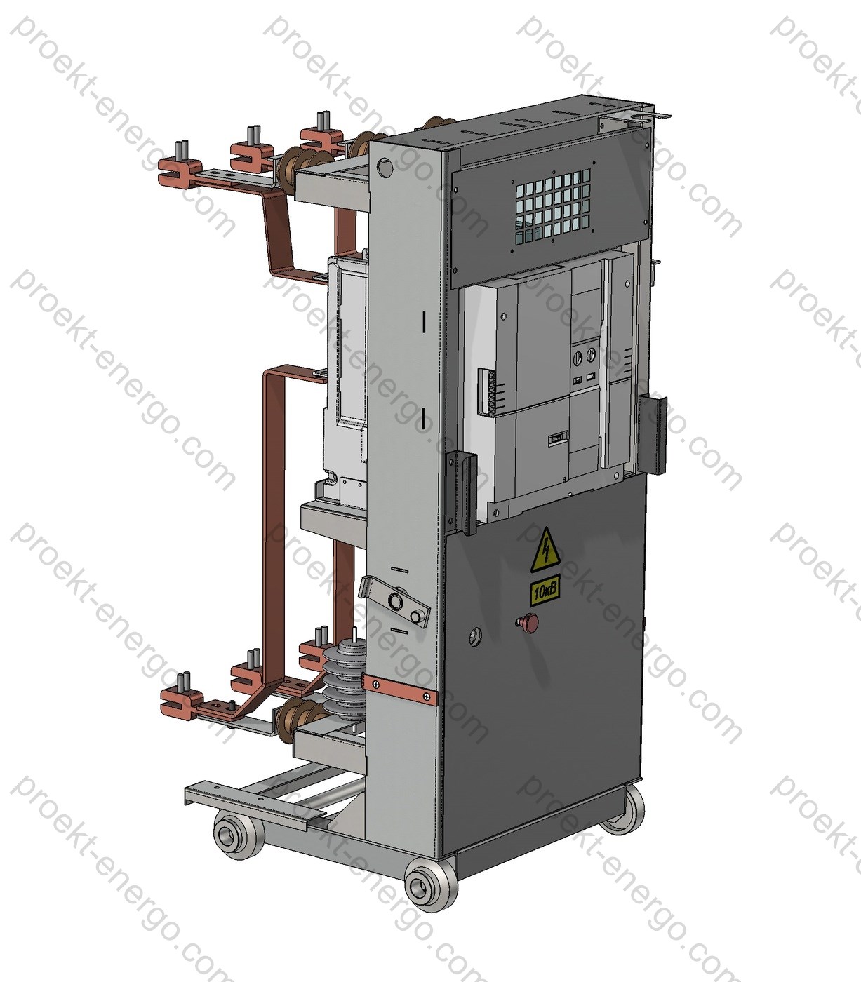
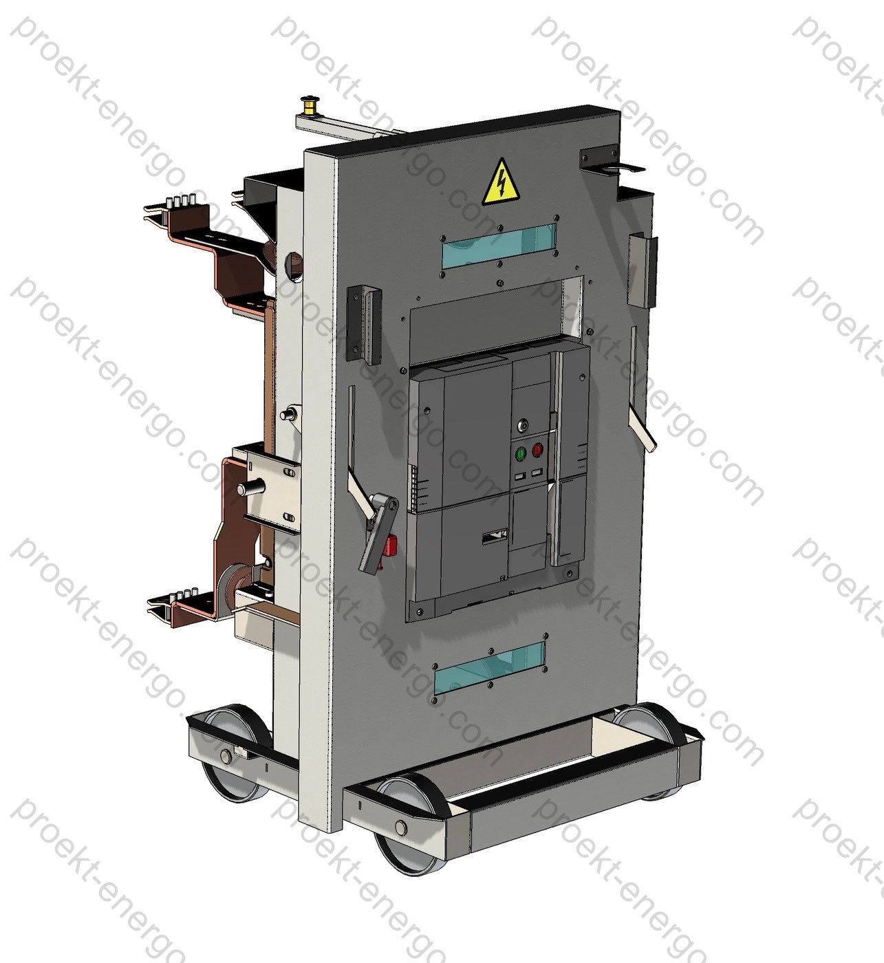
The primary focus is replacement of the most wear-prone and critical unit - the oil circuit-breaker. It is replaced by vacuum or SF6 circuit-breakers with spring-stored or electromagnetic actuators; unlike oil breakers they eliminate oil handling, offer high endurance and compact dimensions. A comprehensive KRU upgrade is also possible: block replacement of the breaker compartment with withdrawable truck, shutter mechanism, earthing switch drive, doors, relay cubicle and updated nameplates/markings.
The reliability of KRU or KSO is directly dependent on the switching equipment. Such modernization is a simple, cost-effective way to mitigate the failure risks of legacy breakers and increase personnel electrical safety.
Retrofitting existing electrical equipment is economically more rational than new procurement, design and installation, with shorter outages and lower costs; periodic overhauls of worn oil breakers do not guarantee the required reliability, while other cell components can be retained.
Purpose and application
The withdrawable-unit retrofit for KRU K-26 (K-XXVI) panels with rated current up to 3150 A is intended to replace obsolete withdrawable units with oil circuit-breakers by modern solutions based on vacuum or SF6 circuit-breakers. The solution targets 6–10 kV distribution networks in industry, power & utilities, mining & metallurgy, municipal infrastructure, refineries, data centers, transport and infrastructure. It is applicable for planned modernization, reliability & maintenance (R&M) programs, and substation refurbishments with limited outage windows.
Main retrofit objectives:
- Increase operational reliability and reduce unplanned outages by introducing modern switching devices with high mechanical and interrupting endurance;
- Bring panels up to current electrical safety practices, incl. internal arc, compartment partitions, interlocks and touch-protection levels;
- Lower total cost of ownership (TCO) by eliminating oil handling, reducing maintenance and simplifying inspections;
- Preserve cable connections, bus bridges, foundations and the switchboard envelope, minimizing civil works and downtime.


Technical data
| Parameter | Value | |
|---|---|---|
| Rated voltage, kV | 6 / 10 | |
| Rated main-circuit current, A | up to 3150 | |
| Rated short-time withstand current, kA (3 s) | 31.5 (opt. 25/40) | |
| Rated peak withstand current, kA (peak) | up to 80 | |
| Lightning/operating impulse withstand voltage, kV (BIL) | 60–95 (per project) | |
| Degree of protection, front/inside | IP31 / IP2X (higher on request) | |
| LSC category / partition class | LSC2B / PM (per project) | |
| Internal arc classification (IAC) | AFL or AFLR 20–31.5 kA, 0.5–1 s (with gas duct) | |
| Circuit-breaker mechanical endurance, operations | up to 30 000 (depends on series) | |
| Control supply type and frequency | AC/DC, 50/60 Hz, 110–230 V | |
| Withdrawable unit positions | Disconnected / Test / Service | |
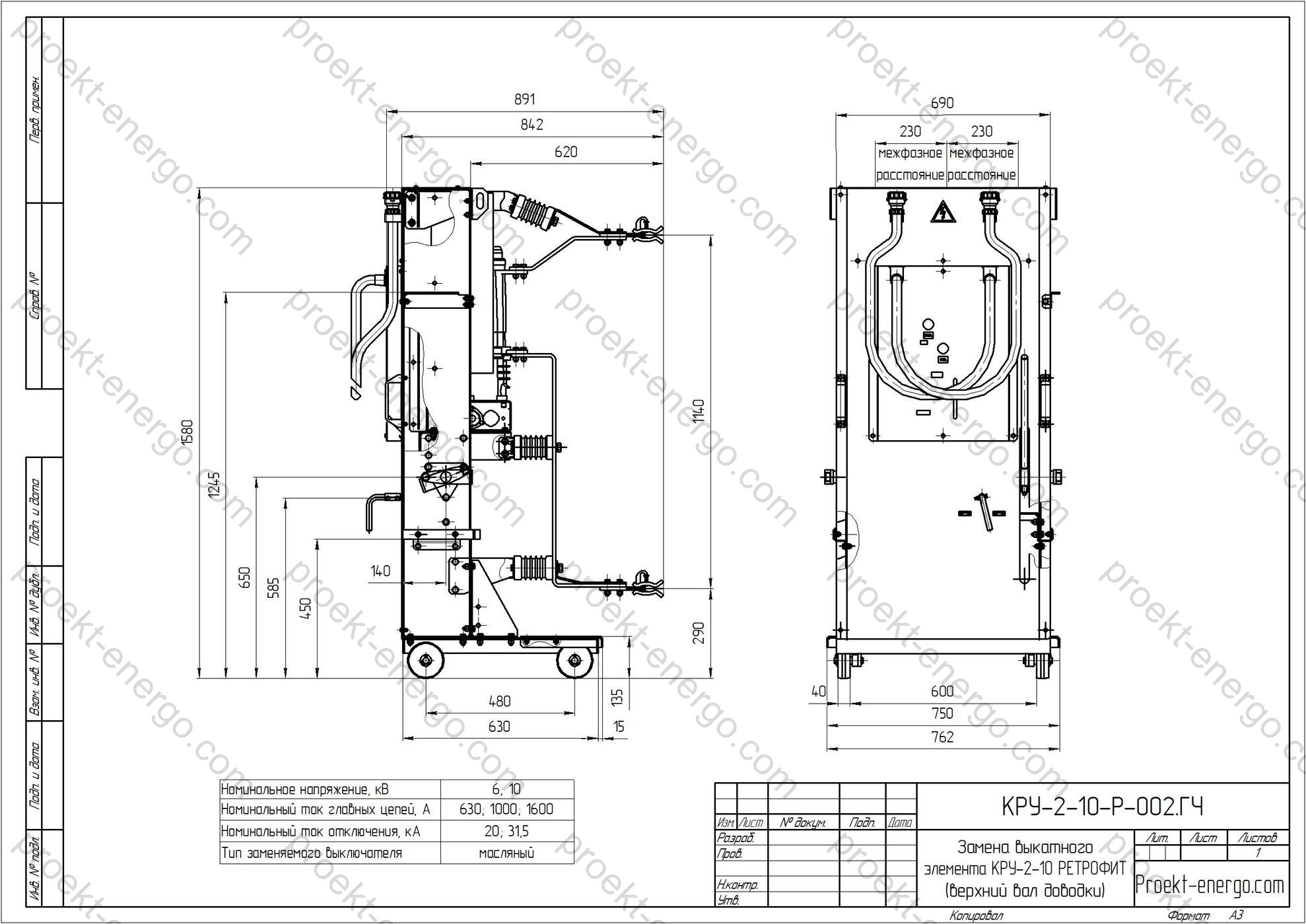
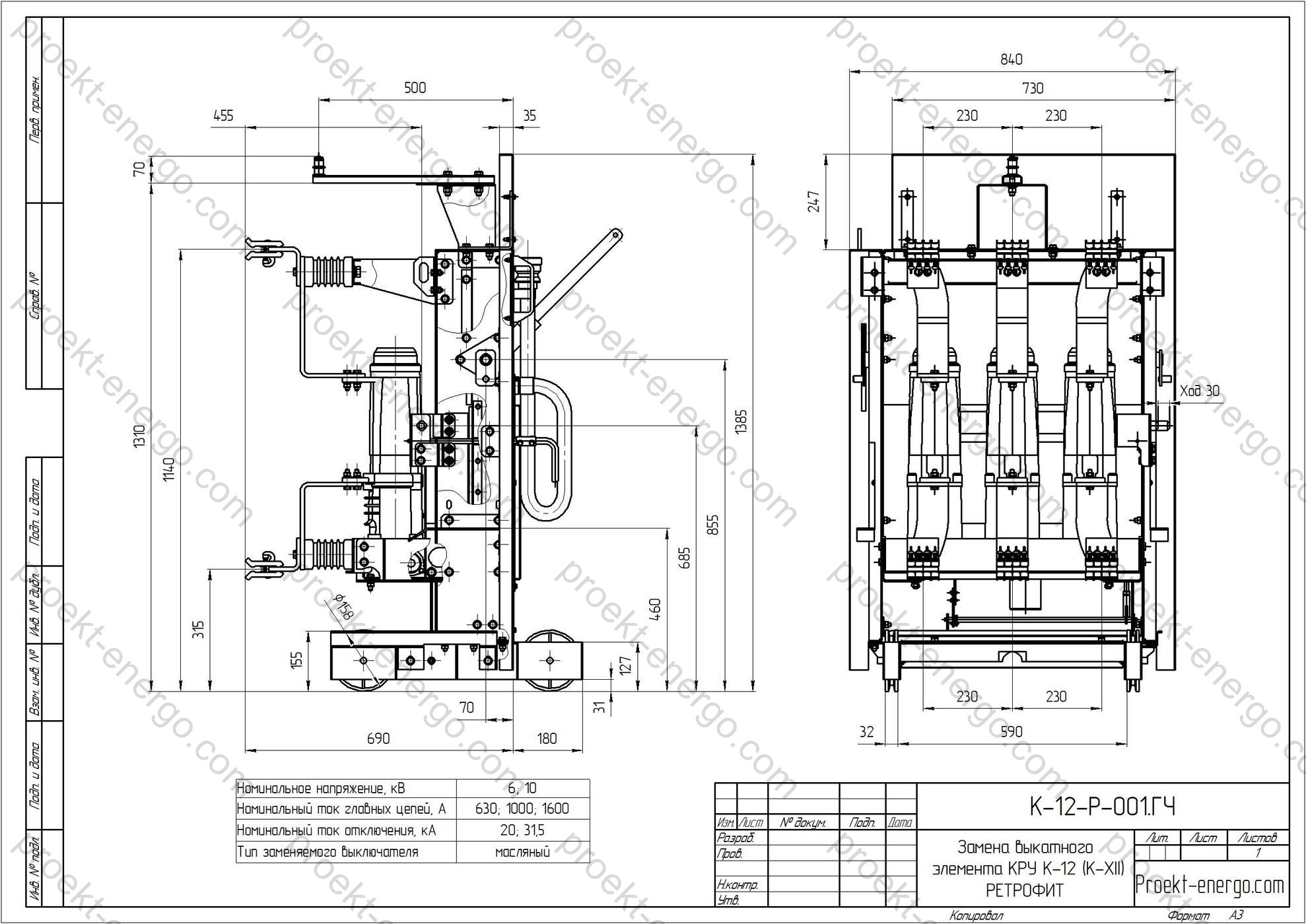
| Withdrawable unit dimensions | Adapted to K-26 opening (no change to panel body) | |
| Withdrawable unit mass, kg | depending on execution (approx. 250–400) | |
| Operating ambient temperature range, °C | –5…+40 (extensions on agreement) | |
| Altitude of installation, m | up to 1000 (above - with derating) | |
Note: exact values depend on the selected breaker series and project-specific type tests. If required, internal arc classification (IAC), LSC category and partition class PM/PI, as well as additional client requirements (seismic, climate, coating, degree of protection) are confirmed by project.
Service conditions
The retrofit kit is engineered for operation in indoor rooms with natural ventilation in environmental categories per EN/IEC 60721-3-3 (indoor use). Typical conditions:
- ambient air temperature: from –5 °C to +40 °C (short-term up to +45 °C);
- relative humidity: up to 95 % at +25 °C without condensation;
- altitude above sea level: up to 1000 m without derating (above - parameters by design);
- pollution category: normal, without chemically aggressive vapors, conductive dust and vibration beyond typical process equipment limits;
- seismic: up to intensity 7 with appropriate fastening and stability verification;
- enclosure protection: typically IP31 at the front, IP2X within compartments, higher by project.
For special conditions (marine atmosphere, heavy dust, high humidity/condensation, low-temperature areas) the retrofit module design and materials are adapted: reinforced coatings, additional heaters/ventilation, sealing, anti-corrosion executions, higher IP rating, and provision for diagnostic sensors (temperature, humidity, partial discharge).
Layout and design solutions
The K-26 withdrawable-unit retrofit is implemented in three typical executions: adaptation of the existing withdrawable unit, full replacement of the withdrawable unit, and a modular “hard-bus retrofill” solution (OneFit-type) consisting of an adaptation module and a standardized withdrawable assembly. The option is selected after an instrumented survey of the cell and operating-risk analysis.
- Adaptation of the existing withdrawable unit. Installing a vacuum/SF6 circuit-breaker on the original truck via an adapter frame and contact adapters; overhaul and re-setting of mechanical linkages, guide re-alignment, shutter mechanism replacement, modernization of the secondary plug. Advantage - minimal metalwork. Notes - alignment and interlock check/setting required; type checks of insulation and mechanics are recommended after assembly.
- Full replacement of the withdrawable unit. Supply of a new withdrawable truck in K-26 dimensions and connection interfaces, compatible with the interlock system and “disconnected/test/service” positions. Ensures quick commissioning, reduces body modifications; the old unit with oil breaker can be kept as backup if needed.
- “Hard-bus retrofill” module (OneFit concept). A factory module installed in the breaker compartment without intervention in busbar systems; includes the interface to existing primary conductors, integrated shutters, interlock system and guides. Provides improved creepage/clearance distances and withstand levels, standardized maintenance, closed-door racking in/out and optional motorized remote racking (by project).
Key design features of the retrofit kit:
- Switching device. Vacuum or SF6 circuit-breaker of suitable interrupting class (6–10 kV, 25–31.5–40 kA), endurance up to 30 000 mechanical operations depending on series, options with motor-charging and readiness for auto-reclosing (AR) / automatic transfer (ATS) schemes.
- Primary circuit interface. Custom adapters to mate with the panel’s fixed contacts, optimization of contact pressure; if required - replacement/re-setting of tulip contact assemblies.
- Shutter mechanism. New shutters with independent phase actuation, interlocks against mal-operations, visual position indication.
- Earthing switch. Possible installation/replacement of the earthing switch drive and contacts with making capacity to the required peak withstand level.
- Interlocks. A set of mechanical and electrical interlocks: no racking with the breaker closed, no breaker closing with shutters open, mutual interlocks with the earthing switch drive and doors; optional key/solenoid interlocks.
- Secondary circuits. New removable multipin plug with pinout aligned to existing schemes; relocation of control relays, terminal blocks, modern interfaces (dry contacts, Modbus/IEC 61850 at the protection IED level).
- Diagnostics and digitalization. Temperature sensors on primary joints, vibration/drive-life monitoring, operation counter, IEC 61850 integration (GOOSE/MMS), provision for remote HMI, remote racking and closed-door maintenance.
Typical equipment replacement options
1) Replace the circuit-breaker with a new one on the existing withdrawable truck via an adaptation kit, with updated interlocks and secondary plug; linkage alignment required. The lowest-cost but the most time-consuming option.
2) Replace the entire withdrawable unit with a new one fully compatible in dimensions and interfaces; interlocks correspond to the existing system. A fast option requiring minimal modifications; the old unit with oil breaker can serve as backup.
3) Use a factory “hard-bus retrofill” module (OneFit-class) - a ready module with breaker, implemented mechanical/electrical interlocks, protective shutters and adapted primary contacts. Advantages:
- improved clearances and creepage distances;
- type-tested design and unified maintenance procedures;
- higher mechanism reliability and standardized O&M; closed-door racking available.
Safety
The retrofit module is engineered to enhance personnel safety:
- Internal arc. Solutions can be supplied with internal arc classification IAC AFL or AFLR for the specified current/time (e.g., 20–31.5 kA for 0.5–1 s) with proper gas exhaust and compartment sealing - project-specific.
- Closed-door operations. Racking to “test/service”, breaker and earthing switch operations are performed with doors closed (when corresponding drives are provided), reducing arc-flash exposure.
- Compartment partitions. Metal partitions between compartments, contact shutters, screens and bonding of moving parts provide the required touch protection and limit arc propagation.
- Interlocks and indication. Mechanical and electrical interlocks prevent mal-operations; status indication for all operating elements is placed on the front panel.
- Active arc protection. Optional optical arc-flash protection systems accelerate tripping.
Manufacturing options
- Based on a vacuum circuit-breaker with rated breaking capacities 25/31.5/40 kA, current up to 3150 A.
- Based on an SF6 circuit-breaker for applications with stringent interrupting/endurance requirements.
- Shutter system - standard or reinforced, with independent actuation per phase.
- Earthing switch drive - manual or motorized; earthing switch with making capacity.
- Protection & control - from re-using existing relays to deploying digital IEDs and process bus.
- Sensors & monitoring - temperature labels, thermal sensors on joints, drive vibration sensors, operation counter, monitoring interfaces.
- Coatings & paints - standard / enhanced anti-corrosion for aggressive environments.
| Scenario | Commissioning time | Metalwork scope | Compatibility | Cost |
|---|---|---|---|---|
| Adapt existing truck | Medium | Minimal | High (if geometry retained) | Low |
| Full replacement of withdrawable unit | Short | Minor | Guaranteed | Medium |
| “Hard-bus retrofill” module (OneFit-class) | Short | No intervention in busbars | High (standardized) | Medium / above medium |
Standards compliance
Retrofit solutions and devices are designed in accordance with applicable norms. Project confirmations may include:
- IEC 62271-1 - general requirements for medium-voltage switchgear and controlgear;
- IEC 62271-200 - metal-enclosed medium-voltage switchgear (LSC, PM/PI, IAC);
- IEC 62271-100 - AC circuit-breakers;
- IEC 62271-102 - disconnectors and earthing switches;
- IEC/EN 60529 - degrees of protection (IP Code);
- Environmental categories - indoor installation per EN/IEC 60721-3-3.
Partnering with contractors and OEMs
We welcome cooperation with electrical equipment manufacturers, installation companies, design institutes and investors interested in serial production and deployment of retrofit solutions for KRU K-26. Collaboration formats: licensing of design documentation under partner’s brand, contract manufacturing cooperation (metalwork, machining, painting, assembly), technical support of pilot projects, joint participation in EPC/EPCM tenders, personnel training and supervisory installation.
Documents
The supply includes a package of design and O&M materials:
- Drawings - overall and interface, part/assembly BOMs (DWG/DXF, PDF);
- 3D models of units and assemblies (STEP/Parasolid), optionally native sources for SolidWorks/Inventor;
- Electrical schematics - principal and secondary wiring, pin-out maps for plugs;
- Instructions for installation, alignment, interlock checks and primary tests; maintenance schedules;
- Templates - datasheets and technical requirements, product passports and test reports.
Why work with us:
- No need to maintain highly specialized engineering staff - you receive a complete documentation set for manufacturing; an engineer of average qualification can work with it.
- No need to build prototypes - our experience allows launching serial production successfully.
- Working to our documentation, your staff will be consulted on all nuances of replacing the withdrawable unit of KRU K-26 (K-XXVI) 3150 A.
For additional information on replacing the withdrawable unit of KRU K-26 (K-XXVI) 3150 A (retrofit), please contact: inbox@proekt-energo.com
PDF - Download technical information on the KRU K-26 (K-XXVI) 3150 A withdrawable unit replacement (retrofit)


