- We offer co-operation on replacement of old installed equipment on equipment at substations with new equipment produced at your factory. We have a large database of documentation for old, end-of-life equipment, and we will adapt your products to replace the old.

- Design of substation equipment in accordance with the technical specifications.

- Design documentation for the manufacture of electrical equipment.

- 3-D models, product drawings, BOM.

- Preparation of technical documentation for participation in tenders.

- Preparation of preliminary standards for material consumption for cost calculation..

- Consulting on projects.

..since August 1998

Proekt-Energo

Area of activity:

- Design of low-voltage, middle-voltage and high-voltage electrical equipment of substations for voltages of 0.4 - 220 kV.
- Development of working documentation in accordance with the technological capabilities of the plant.
- Preparation of preliminary technical documentation for participation in tenders for the supply of equipment.
- Consultations on project approvals.
- Supporting the production of equipment at the plant.

Specialization:

- Switchgear for indoor and outdoor installation for voltages of 6, 10, 20, 35 kV.
- Air-insulated secondary switchgears AIS for voltages 6, 10 kV.
- Complete transformer substations CTS for voltage 10 - 220 kV.
- Disconnectors for voltage 0.4 ... 220 kV.
- Drive to disconnectors.
- Replacement of withdrawable elements and switches in existing switchgear (Retrofit).
- Low-voltage switchgears for voltage 0.4 kV.
- DC 600V switchgears RU-600.

GN19-12 Indoor AC Disconnector (Disconnect Switch)

The GN19-12 indoor alternating-current disconnector is intended for no-load isolation (make/break without load current) of medium-voltage circuits with a maximum equipment voltage up to 12 kV (50/60 Hz). The GN19-12 family comprises three-pole vertical-rotary knife-type devices for metal-enclosed AIS/MV switchgear cubicles. Flat-mount and through-wall (GN19-12C) versions are available to separate the operating handle from the live parts; options include a manual operating mechanism CS6-1 and a “live-presence” indicator.

Purpose and Application

The GN19-12 provides a visible isolating distance for operational switching, scheduled maintenance and repair within 6–10 kV MV switchgear (insulation level up to 12 kV): incoming and bus-section cubicles, busbar compartments, feeder/transformer connections, and distribution substations. The device is used to place de-energized sections in and out of service, strictly without load or short-circuit current, and enables:

  • operational isolation of the work area - a visible break by the knife blade;
  • safe access when mechanical interlocks with switchgear doors and the circuit breaker are applied;
  • inter-section and maintenance switching in standard MV schemes;
  • integration into SCADA/remote control via auxiliary contacts and limit switches (options).

Extended use cases. GN19-12 serves as a bus or feeder disconnector / disconnect switch in AIS cubicles such as KYN28A-12, XGN2-12 and equivalents where compact size, robust mechanics and direct visual confirmation of isolation are required. In “incoming/tap-off” feeders, bypass lines, transformer/reactor circuits and capacitor banks, the disconnector localizes the work zone, provides galvanic separation, and supports inter-section operations with no load. For enhanced safety, an earthing/grounding switch (e.g., JN15-12) is often installed in the same panel with key interlocks to the operating mechanism to prevent incorrect sequences.

Through-wall version GN19-12C. Used where separation of the operator area and the power compartment is required: handle and position indication on the front, current-carrying parts behind a metal barrier. This increases operational safety, simplifies maintenance and makes visual isolation checks easier.

Industries and geography. Target markets include China, Africa, Asia, Europe and the USA; suitable for 50/60 Hz systems. Typical applications: industrial distribution (mining, metallurgy, oil & gas, data centers), municipal and plant substations, and small/medium generation. “Anti-pollution” and high-altitude versions with increased creepage distances are available for dusty, humid or elevated-site service.

Typical RFQs (for buyers/specifiers): rated current (400/630/1000/1250 A), phase spacing (210/230/250/275 mm), mounting type (standard/through-wall), presence of an operating mechanism, live-presence indicator, compatibility with AIS cubicles and package substations, plus price, lead time, datasheet, drawings (DWG/DXF) and 3D models (STEP/IGES). Common English search terms: “GN19-12 indoor disconnector/isolator 12kV”, “GN19-12C through-wall”, “12kV knife disconnect (no-load)”.

Thanks to its compact mechanics and mounting variants, GN19-12/GN19-12C integrates easily into existing and new cubicles; “anti-pollution” and high-altitude executions are offered for harsh environments. Design and terminology follow IEC practice; for North American projects, coordinate with the applicable IEEE/ANSI C37 series for metal-enclosed switchgear.
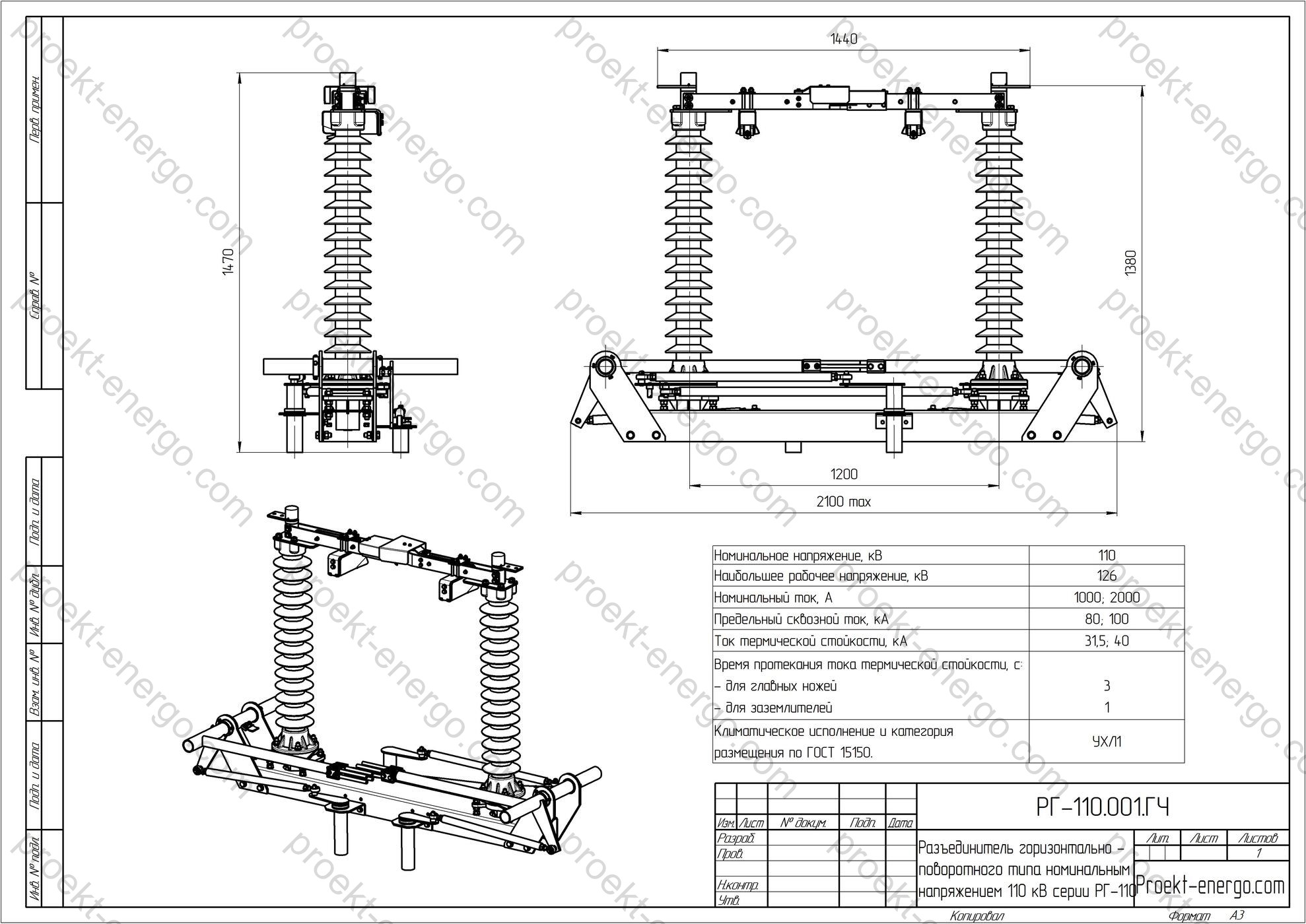
Technical Data

Rated voltage, kV 10
Maximum system voltage (Um), kV 12
Rated continuous current, A 400; 630; 1000; 1250
Short-time withstand current (4 s), kA r.m.s. 12.5; 20; 31.5; 40
Peak withstand current (dynamic), kA peak 31.5; 50; 80; 100
Power-frequency withstand (1 min), kV (phase-phase/phase-earth; across open gap) 42 / 48
Typical phase spacing, mm 210; 230; 250; 275
Mechanical endurance (main circuit) per IEC 62271-102 class M1/M2 (by execution)
Typical switchgear compatibility AIS cubicles KYN28A-12, XGN2-12 (verify per project)

Values above are typical for the GN19-12 family: 400–1250 A continuous; 12.5–40 kA (4 s) short-time and 31.5–100 kA peak; 1-minute 50/60 Hz withstand 42/48 kV. Exact ratings are confirmed in the delivered datasheet for the selected configuration.

Service Conditions

  • Location: indoor installation (MV switchgear cubicles, AIS/metal-enclosed).
  • Ambient temperature: standard -15 °C to +40 °C; low-temperature versions to -25 °C.
  • Altitude: up to 1000 m (higher altitudes require insulation re-rating/high-altitude execution).
  • Relative humidity: daily up to 95 %, monthly up to 90 %, without condensation.
  • Seismic capability: up to 8 degrees (as per manufacturer’s specification).
  • Atmosphere: non-conductive dust only; free of corrosive gases and excessive vibration per MV switchgear practice.

Ensure cabinet ventilation, manage local heating, maintain minimum clearances and creepage distances, and consider heaters/dehumidifiers where required to preserve dielectric strength, especially in dusty or humid rooms.

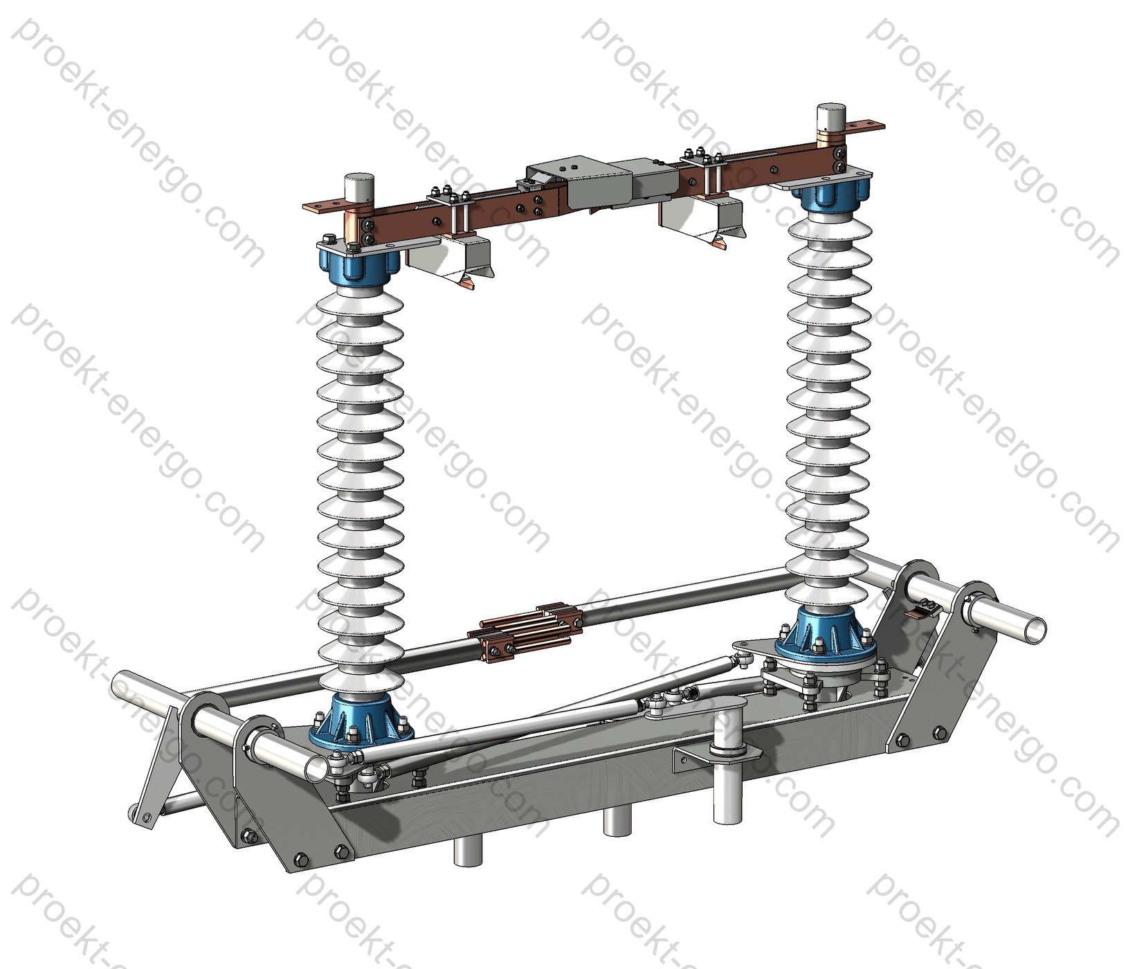
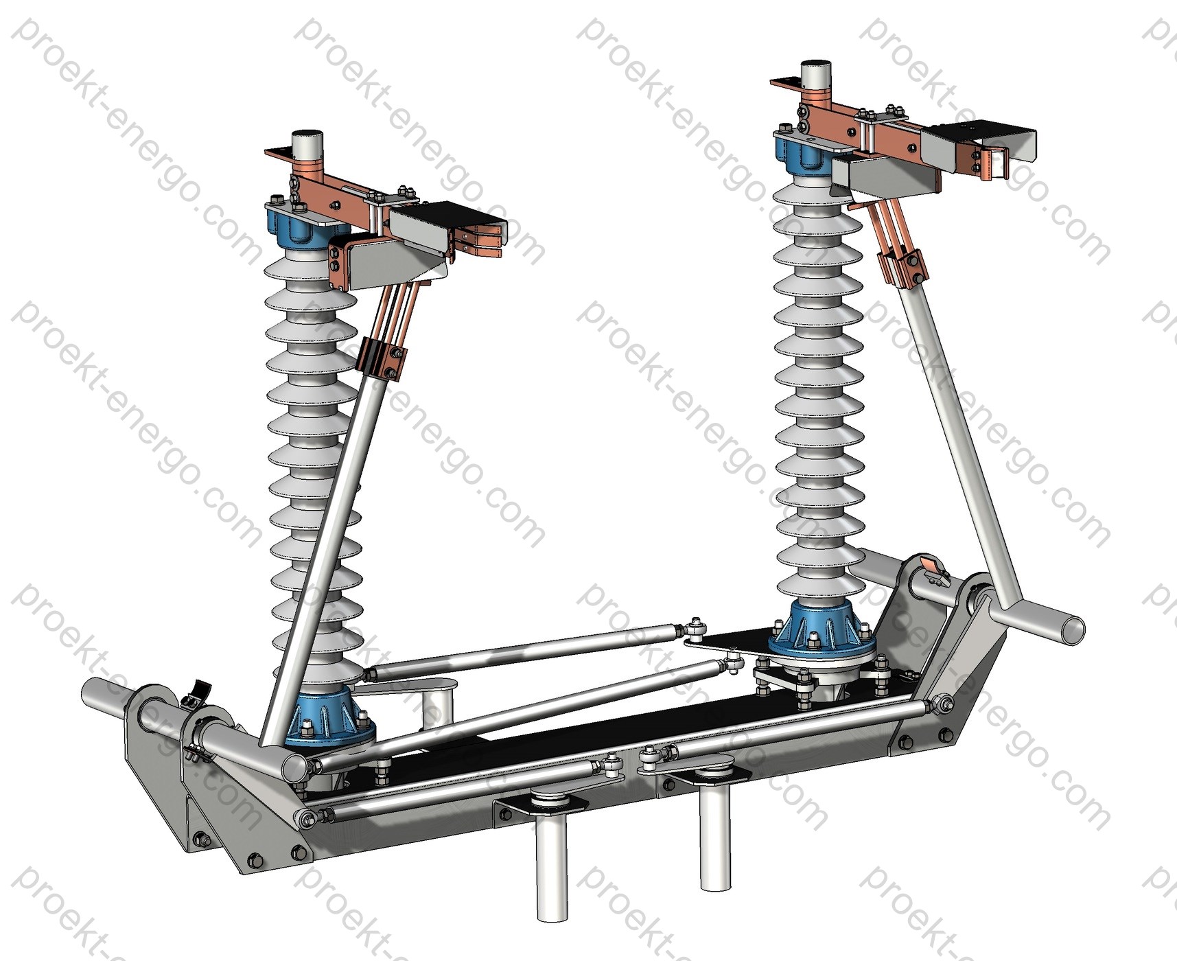
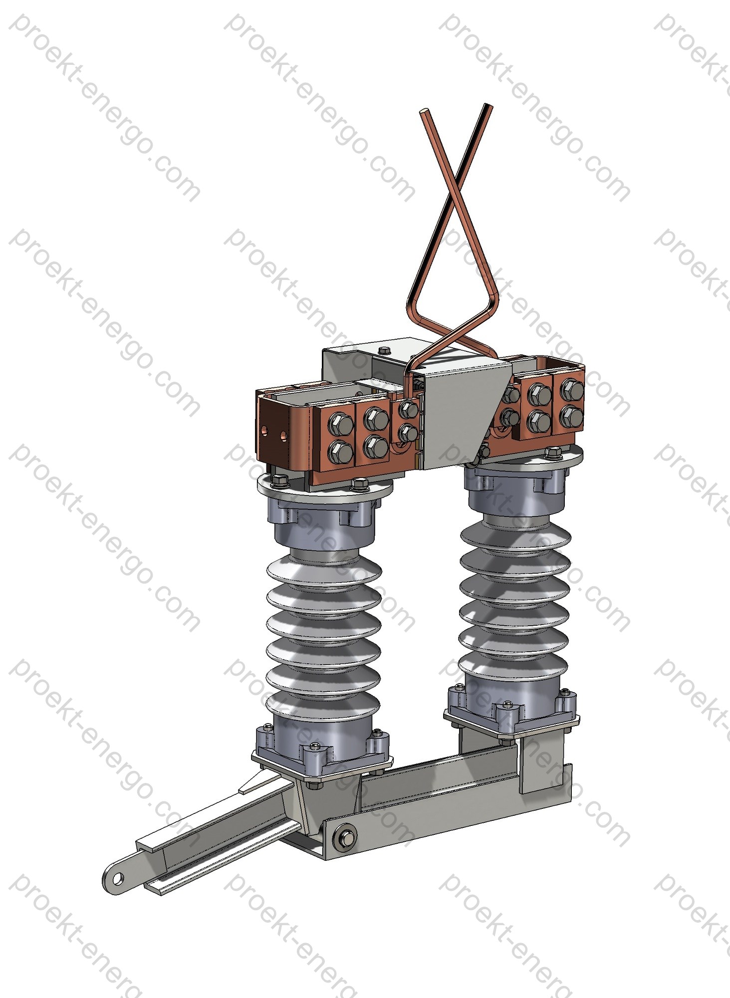
Design and Construction

The GN19-12 is a three-pole device on a rigid steel frame featuring: support/bushing insulators (porcelain/epoxy), vertical-rotary knife blades with spring contact pressure, a reinforced contact system with low contact resistance, a link-lever operating train synchronizing all poles, and a manual CS6-1 mechanism (option: limit switches/auxiliary contacts for SCADA/telecontrol). The GN19-12C “through-wall” execution places the handle on the front while the live parts remain behind a partition, improving ergonomics and safety in compact AIS cubicles.

AssemblyFunctionDesign features
Base frame Mounting for poles and mechanism Welded, high rigidity, adjustable mounting holes
Support/bushing insulators Dielectric insulation & mechanical support Porcelain or cast epoxy; increased creepage
Knife blades Visible isolation Vertical-rotary; spring-assisted contact pressure
Contact system Reliable current path Reinforced fingers; wear-resistant plating
CS6-1 operating mechanism Positions ON/OFF Options for auxiliary/limit switches

Safety and Interlocks

Safety is achieved by the visible isolating distance, mechanical interlocks with doors and the circuit breaker, and the use of auxiliary/limit switches to provide “OPEN/CLOSED” status and inhibit incorrect operations. In the GN19-12C version, segregating the mechanism from live parts with a metal barrier further reduces operational risk.

Versions and Options

The GN19-12 family offers multiple variants to fit project and cabinet requirements:

  • GN19-12 (flat mount) and GN19-12C (through-wall mount);
  • rated currents 400/630/1000/1250 A; phase spacing 210/230/250/275 mm;
  • left/right handle orientation;
  • short-time withstand (4 s) 20/25/31.5 kA (up to 40 kA for 1250 A on request);
  • options: auxiliary switch (ON/OFF), live-presence indicator, anti-pollution and high-altitude executions.

Option sets and compatibility are confirmed at order stage. For commercial requests, specify price, lead time, Incoterms, required drawings/models and switchgear compatibility.

Partnerships and Contractors

We collaborate with electrical equipment manufacturers, MV switchgear integrators, EPC contractors and investors interested in localized production of the GN19-12 series. We offer:

  • transfer of design packages (from preliminary specs to full production documentation);
  • adaptation to your manufacturing capabilities (tooling, machining, plating, coating);
  • sourcing and qualification of suppliers (insulators, stamping/machining, sub-assembly);
  • support on FAT/SAT procedures, test programs and reporting;
  • ramp-up assistance, personnel training and commissioning support.

Available Documentation

Available tender documentation (data inquiry sheets, specs, explanatory notes) and a full set of manufacturing documents for your site:

  • part/assembly drawings (DWG/DXF), BOMs and lists;
  • 3D models (STEP/IGES/Parasolid (x_t), SolidWorks, Inventor);
  • electrical diagrams, interlock charts, cable lists, SCADA/remote-control schemes;
  • assembly/adjustment instructions, inspection routes, test programs;
  • typical O&M documents (datasheet, manual, test forms).

On request, the package is tuned to project needs: busbar thickness, connection interfaces, mechanism type and limit-switch positions, insulator types, phase spacing, etc.

Why Work with Us

- No need for a large in-house engineering team: you get a ready-to-build documentation set.
- Start from serial batches with minimal rework and full technical support.
- Expert guidance on GN19-12 manufacturing and testing, plus assistance with tooling and QA programs.

For additional information on GN19-12 disconnectors: inbox@proekt-energo.com

PDF - Download technical information for GN19-12.

pdf

RG-110 Horizontal-rotary disconnector, rated voltage 110 kV

The RG-110 series of horizontal-rotary disconnectors is designed for safe making and breaking of de-energized sections of substation circuits and distribution facilities of the 110 kV class, as well as for reliable earthing of disconnected sections by means of built-in earthing switches integrated with the apparatus. In 110 kV air-insulated switchyards (AIS), the RG-110 performs operational isolating to provide a visible break, busbar sectionalizing, feeder transfer/backup, and supports switching for maintenance, testing and insulation tests. The disconnector is intended for long-term outdoor service and integrates into typical 110/35/10 kV substation schemes: single and one-and-a-half busbar systems, 110 kV line bays, power-transformer bays, and AIS yards.

Purpose and application

RG-110 apparatus is applied at both new-build and retrofit substations, in distribution points and grid nodes, at industrial sites and infrastructure facilities (rail traction, metallurgy, petrochemicals). Core functions: creating a visible isolation gap for safe personnel access; no-load switching of individual busbar sections and feeders; scheme reconfiguration for contingency transfer; applying and removing earthing on equipment terminals for work. When equipped with a motor drive, and in accordance with the manufacturer’s instructions, switching of power-transformer magnetizing current and 110 kV line/cable charging currents is permitted, which simplifies commissioning, outages for maintenance and routine operations.

Disconnectors are available in single-, two- and three-pole versions. The pole coupled to the operating mechanism is the leading pole. Configurations include a “blade-on-post” single-side-break arrangement with horizontal rotation of the current-carrying blade by 90° (main circuit) and 90°/180° (earthing switch). The design ensures stable contact pressure, low contact resistance and high short-circuit withstand appropriate for the 110 kV class. In retrofit projects, RG-110 is suitable as a replacement for obsolete two-column series while preserving mounting interfaces and inter-phase spacing, and for expanding busbar sections by modular addition of new poles.

Technical data

Rated voltage, kV 110
Maximum system voltage, kV 126
Rated current, A 1000; 2000; 3150
Rated peak withstand current, kA 80; 100; 125
Rated short-time withstand current, kA 31.5; 40; 50
Duration of short-time current withstand, s
– main blades
– earthing switches

3
1
Creepage distance of external insulation, cm, not less than 200
Conductor tension in the horizontal plane incl. wind, N, not less than 800; 1000
Minimum clearances from live parts to various elements of the disconnector (in air), mm:
– from live parts to grounded structures;
– between live parts of different phases;
– between the open contacts of one pole
 

– 900
– 1000
– 900

Service conditions

RG-110 disconnectors are manufactured for environmental conditions classified per IEC 60721-3-4 (stationary use at non-weather-protected locations). Operating temperatures from -60 °C to +40 °C; altitude up to 1000 m. Allowable wind speed in service: up to 40 m/s with no icing and up to 15 m/s with ice thickness up to 20 mm. Mean annual relative humidity up to 80 % at +15 °C. Maximum wind pressure: 700 Pa without icing and 140 Pa with ice cover. For areas with heavy pollution and salt fog, versions with increased creepage distance and shielding are available, including polymer insulators with enhanced hydrophobicity. Dielectric performance is in accordance with IEC 62271-1 and insulation coordination per IEC 60071-1/-2 for the 110 kV class; typical creepage distances are selected to IEC 60815 by pollution severity class I–IV.

Degrees of protection for drive enclosures and terminal boxes are selected to project requirements per IEC 60529; typically not lower than IP54 for outdoor drive cabinets. Resistance to mechanical environmental effects can be provided to the IEC 60068-2 series (vibration, shock) for sites with increased vibration and seismicity (as specified by the project).

Layout and design solutions

Each RG-110 pole comprises a base frame, a support column with a post insulator, a rotating shaft with linkage, the main current-carrying blade, fixed and moving contacts, and an earthing-switch assembly (if fitted). Maintenance-free bearing supports and sealed joints are used in moving parts, eliminating routine lubrication over the service life. Current-carrying contact surfaces are copper with galvanic plating (tin/silver); floating contact packs with silver plating provide constant contact pressure and low resistance over many operating cycles. Shielding parts and corona rings minimize local field intensification at sharp edges of live parts.

The kinematic scheme ensures precise pole synchronization, adequate contact overlap in the closed position and a guaranteed visible break when open. Operating torque from the manual or motor drive is transmitted to the leading pole via links and cardan joints; follower poles are coupled by rods, preventing inadvertent closing under wind or electrodynamic forces. Structural rigidity of the frame is achieved with welded profiles hot-dip or thermodiffusion galvanized; aluminum covers and shields resist corrosion and icing. All bolted joints are secured with locknuts/washers; torque-check marks are provided.

The insulating part can be supplied on porcelain or polymer support/bushing insulators. For harsh environments, extended insulators with increased creepage and anti-icing hoods are available. Connection of both flexible and rigid busbars is provided; on request, transition pads, adapters for tubular bus and flange clamps for various busbar stacks are supplied. Mechanical endurance is at least 10 000 “close-open” cycles, matching long service in 110 kV distribution networks with typical operation counts.

Key design assemblies Execution features
Main-circuit contact system Silver/tin coatings, floating contact packs, stabilized pressure, low contact resistance, corona rings.
Support/bushing insulators Porcelain or polymer; creepage length per pollution severity; anti-icing hoods.
Operating linkage Maintenance-free bearings, sealed joints, temperature-compensation features, position interlocks.
Corrosion protection Hot-dip/thermodiffusion galvanizing of steel parts; aluminum shields; protected fasteners.

Safety and interlocks

The interlocking system prevents mal-operations and ensures personnel safety. Mechanical interlock blocks closing of the earthing switch when the main blades are closed, and conversely blocks closing of the main circuit when the earthing switch is closed. End-position latches are provided, with the ability to apply padlocks (lockout/tagout, LOTO) on the manual-drive handle and on pole levers. Electrical interlock and limit switches (e.g., KSAM-type or equivalent) provide discrete signals “CLOSED/OPEN” for the main circuit and “EARTHED”; groups of auxiliary contacts can be installed for SCADA/DCS and protection & control (PAC). Mechanical position indicators are visible from the operating level.

With proper adjustment of the linkage, self-movement under wind loads or short-circuit forces is excluded. Procedures for checks, contact-overlap adjustment, limit-switch setting and operating-force verification are described in the service documentation and performed during commissioning.

Variants and options

The RG-110 product line provides a wide range of options to adapt to site and client requirements. Typical options include:

Option Description
Drive type Manual PRG-6 (outdoor) with electromagnetic interlock; motor PD-14 with local/remote control.
Earthing switches Without earthing switch / with one or two earthing switches (on the moving- or fixed-contact side).
Insulation Porcelain (pollution classes I–II) or polymer (up to class IV); extended creepage for marine/industrial areas.
Pole arrangement Three-pole with inter-pole rods; mirror execution; left/right drive; variable inter-phase spacing.
Additional items Corona rings, shielding parts, anti-icing hoods, LOTO guards and tags, service platforms, stands/bases.
Signalling & interfaces Auxiliary-contact groups for SCADA/DCS, limit switches, terminal boxes IP54 and above, cable glands per project.

Drives and control

Operation of main blades and earthing switches is performed by manual PRG-6 drives (outdoor) or by PD-14 motor drives. The manual drive provides fixed end positions with padlocking in the end positions, a folding handle and standard electromagnetic interlock; local control cabinets can be used to install control and signalling devices. The PD-14 motor drive provides remote control and is equipped with a motor-gear unit, limit switches and local controls; AC/DC control circuits are provided as per project. In both cases the linkage geometry and rod lengths are set on site to ensure synchronized pole movement and the required contact overlap.

Standards compliance

RG-110 disconnectors are designed and manufactured in line with current standards and normative documents for medium-voltage switching equipment, including (up to six key documents applicable to this product):

  • IEC 62271-102: AC disconnectors and earthing switches - electrical/mechanical requirements, tests and safety.
  • IEC 62271-1: Common specifications for switchgear and controlgear.
  • IEC 60071-1/-2: Insulation coordination - definitions, principles and application guides.
  • IEC 60529: Degrees of protection (IP code) for enclosures.
  • IEC 60815 (series): Selection and dimensioning of high-voltage insulators for polluted conditions.
  • IEC 60721-3-4: Classification of environmental conditions - stationary use at non-weather-protected locations.

Engagement with contractors and cooperation

We invite cooperation with manufacturing sites, engineering companies, installation and commissioning contractors, as well as investors interested in deploying and localizing production of RG-110 disconnectors. Support is provided at all stages: from pre-design studies and data-sheet definition to serial launch and warranty/post-warranty service. Flexible models are available: supply of a complete design package for in-house manufacturing, contract manufacturing of assemblies and parts at partner plants, or delivery of kits for large-unit assembly at the customer’s site. For bus-duct and steelwork manufacturers, 3D models and interface dimensions are available for AIS layout coordination.

Deliverables and digital models

The documentation package is tailored to the specific project and typically includes: specifications, assembly drawings, parts lists and linkage drawings, schematic diagrams and drive connection diagrams, bill of materials (auxiliary switches, limit switches, interlocks), product passport/manual, test programs and procedures, commissioning logs, as well as 3D models of assemblies and the complete unit in exchange formats (Parasolid/X_T, STEP) and native formats (SolidWorks), DWG/DXF drawings for integration into structural/electrical working documentation. On request we provide models for control-cable routing, interlock schemes and torque-tightening charts.

Our advantages:

– No need to maintain a large team of highly qualified engineering staff - you receive a complete documentation set that can be used by a mid-level engineer.
– No need to build experimental prototypes - our experience allows serial production launch straight away.
– Working to our documentation, your specialists receive full guidance on all manufacturing nuances of RG-110 disconnectors.

Partnership for manufacturers and contractors

– Steelwork manufacturers - we provide frame and support assemblies, overall and interface dimensions for AIS portals; we agree protective coatings and galvanizing requirements.
– Bus-duct manufacturers - we provide adapters and interface dimensions, recommendations on tolerances and drilling templates.
– Commissioning companies - on-site test instructions, signalling/interlock verification procedures, typical SCADA/DCS integration schemes.
– Investors and EPC - effort and cost assessment, supply plan for large-unit assemblies, localization schedules.

For additional information on RG-110 disconnectors please contact: inbox@proekt-energo.com

PDF - Download technical information for RG-110 disconnectors

pdf

RLND (RLNDZ)-10 Outdoor Line Disconnector, Double-Post Type

RLND-10 and RLNDZ-10 disconnectors are intended for making and breaking de-energized sections of medium-voltage circuits that are live (no load switching), as well as for earthing isolated sections by means of fixed earthing switches.
RLND-10 disconnectors are supplied as standard in a three-pole configuration. The main blades open in the horizontal plane (side-break). The equipment is designed for outdoor service in accordance with EN/IEC 60721-3-4; ambient temperature from +40 °C down to -60 °C; wind speed with icing up to 15 m/s; wind speed without icing up to 40 m/s; installation altitude up to 1000 m a.s.l.; ice thickness up to 10 mm.

Technical data

Rated voltage, kV 6; 10
Maximum system voltage, kV 7.2; 12
Rated current, A 200; 400; 630
Rated short-time withstand current, kA 6.3; 10
Rated peak withstand current (electrodynamic), kA 15; 25
Permissible mechanical load on the fixed terminal (incl. wind/icing), N 200
Environmental category (EN/IEC 60721-3-4) Outdoor (stationary, non-weatherprotected)
Insulation category (IEC), I; II I; II
Mechanical endurance of disconnectors and drives, operations (O-C) 2000

Application and scope

RLND (RLNDZ) are outdoor, two-post line disconnect switches for distribution networks rated 6–10 kV (50 Hz). The devices provide a visible isolating gap and ensure safe work on de-energized sections of overhead and cable lines, busbars, jumpers, taps, feeders of distribution points, and outdoor switchyards of package transformer substations. They are used:

  • as line switches on 6–10 kV overhead lines - for operational reconfiguration, sectionalizing, and back-up;
  • in outdoor switchyards - as bus and feeder disconnectors with/without earthing blades;
  • to isolate for maintenance load break switches, reclosers, current/voltage transformers, and surge arresters;
  • for process isolation of inlets to KTP, RP, KRU/KRUN and to meet “visible break” requirements;
  • for operational earthing of de-energized sections via integrated earthing switches (RLNDZ versions).

Disconnectors are intended for off-load switching (in the absence of load current). Depending on the scheme and conditions, switching of small magnetizing inrush currents of unloaded transformers and charging currents of line sections is permissible within limits defined by the project and applicable standards. A clearly visible isolating gap, unambiguous position indication, and the possibility of interlocks make RLND/RLNDZ a basic element for safe operation of distribution networks.

Service conditions

Designed for outdoor operation per EN/IEC 60721-3-4 (stationary, non-weatherprotected locations). Operating temperature range -60 °C … +40 °C. Acceptable wind speeds: up to 40 m/s (no icing) and up to 15 m/s (with icing); ice thickness up to 10 mm; installation altitude up to 1000 m a.s.l. Components exposed to corrosion and icing have protective coatings and shapes that promote self-cleaning by wind and gravity. Live parts are dimensioned for atmospheric influences, humidity and pollution, with creepage distances and clearances meeting insulation categories I/II.

Insulating parts - porcelain or polymer line post insulators with enhanced resistance to UV, tracking and erosion. Mechanical assemblies are rated for repeated open–close cycles at sub-zero temperatures without degradation of contact pressure. For areas with extreme wind/icing loads, reinforced supports and enlarged bases are available.

Design and construction

The double-post arrangement comprises two bearing columns with support insulators linked by a galvanized steel base. One column carries the fixed contact assembly; the other carries the moving blade rotating in the horizontal plane (side-break). Opening/closing is via an operating shaft and linkage system that ensures synchronized blade rotation with a defined angle (typically 90°). RLNDZ versions add an earthing blade on the common frame with its own shaft and mechanical interlock.

  • Current path. Copper or aluminium conductors with bimetallic transition pads at terminals. Contact surfaces are silver-plated to reduce contact resistance and improve corrosion resistance. Spring-loaded contact assemblies provide automatic wear compensation, stabilizing contact pressure over life.
  • Frame and supports. Structural steel with hot-dip galvanizing for long-term corrosion protection. Fastening points use high-strength bolts with self-locking nuts.
  • Bearings. Rotating units on sealed bearings protected from dust and moisture. Depending on version, PTFE/bronze-graphite bushings may be used.
  • Arcing horns and surge arresters. On request, arcing horns and mounting pads for surge arresters can be fitted for local overvoltage limitation.
  • Operating mechanism. Manual lever operator with defined positions; optional motor operator (electric drive) for remote control, with limit switches and mechanical position indicators.
  • Installation. Suitable for mounting on concrete/steel poles, cross-arms and outdoor substation steelwork. Geometry allows “left” or “right” orientation relative to the operating axis, and blade orientation toward the line or busbars.

Creepage distances and clearances are selected for 6–10 kV service, ensuring a visible break for work permits. Flat or branching clamps are used for bus/conductor connections, accommodating aluminium/copper with bimetallic washers.

Safety and interlocking

Personnel safety is ensured by the visible isolating gap, mechanical interlocks, and the possibility to fit locking devices. The design provides:

  • mechanical interlock between the main circuit and earthing switch (it is impossible to close the earthing blade when the main circuit is closed, and vice versa);
  • provisions for padlocks on operating mechanisms and linkages to exclude erroneous operations;
  • clear “ON/OFF/EARTHED” indication on the operator; option to install limit switches for status indication and remote control schemes;
  • travel stops and adjustable end-stops preventing incomplete closing and vibration-induced movement;
  • protective shields on contact assemblies (on request) to reduce risks of accidental contact and the influence of birds/small animals.

The operating documentation includes work-permit guidance, interlock checks, and maintenance intervals. When a motor operator is used, electrical interlocking is implemented in coordination with mechanical interlocks.

Versions and options

Base versions:

  • RLND-10/200, /400, /630 - without earthing switch; three-pole;
  • RLNDZ-10/200, /400, /630 - with fixed earthing switch; three-pole.

Available options:

  • manual or motor operator with remote control (dry contacts, position signalling);
  • left/right arrangement, mirror blade orientation;
  • terminal variants (flat busbars, cable lugs, clamps for ACSR, etc.);
  • enhanced anti-corrosion package (hot-dip galvanizing + paint coating);
  • polymer or porcelain insulators depending on pollution/icing requirements;
  • complete with limit switches, mechanical indicators, pads for surge arresters, and position sensors.

Supply scope (typical)

Item Composition Notes
RLND/RLNDZ disconnector Three poles assembled, frame, linkages, fasteners Factory-set end-stops
Operator Manual lever or motor operator Limit switches on request
Documentation Data sheet, manual, diagram, certificates Electronic copies included
Options Bimetallic pads, shields, surge arresters Per questionnaire

Options and accessories

Option Purpose Comment
Motor operator Remote operations, SCADA With position limit signals
Limit switches Position indication “ON”, “OFF”, “EARTHED”
Polymer insulators Improved pollution performance UV-resistant, low mass
Anti-corrosion package Durability in aggressive environments Hot-dip galvanizing + coating

Compliance with standards

Design, manufacturing and testing comply with applicable standards for this class of equipment, including:

  • IEC 62271-102:2018/A1:2022 - “High-voltage switchgear and controlgear - Part 102: Alternating current disconnectors and earthing switches”;
  • IEC 62271-1 - “High-voltage switchgear and controlgear - Part 1: Common specifications” (relevant clauses);
  • EN/IEC 60721-3-4 - “Classification of environmental conditions - Part 3-4: Stationary use at non-weatherprotected locations (outdoor)”;
  • IEC 60815-1 - “Selection and dimensioning of high-voltage insulators for polluted conditions” (creepage distance guidance);
  • DSTU EN 62271-102:2016 - national adoption of IEC requirements for Ukraine.

We offer documentation for manufacturing RLND-10 and RLNDZ-10 disconnectors:

– Preliminary technical documentation for tenders to manufacture RLND-10 and RLNDZ-10. We will prepare the information needed to assess feasibility in line with tender requirements and data sheets.
– Detail drawings, 3-D models and other documentation to manufacture RLND-10/RLNDZ-10 at your facility. If in-house fabrication of parts is not planned, we will help outsource them. Final assembly and mounting will be performed at your site.
– All documentation can be adapted to project requirements and to your plant’s manufacturing capabilities.
– If other manufacturers’ equipment is installed at the substation, we will prepare documentation to manufacture matching equipment as an addition to the installed base.

Benefits of working with us:

– No need to maintain a large team of highly qualified engineers - you receive a complete documentation set that can be handled by a mid-level engineer.
– No need to build pilot prototypes - our experience allows immediate start of serial production.
– Working to our documentation, your specialists will receive consulting on all nuances of manufacturing RLND-10/RLNDZ-10.

Engaging contractors and production partners

We build cooperation with steelwork, galvanizing, machining and die-casting plants to launch serial batches of RLND/RLNDZ. Where needed we involve insulator manufacturers (porcelain/polymer), suppliers of bimetallic pads and high-strength fasteners. For investors we offer standard techno-economic models, loading plans and starter permitting packages for organizing an assembly line/workshop. We conduct production ramp-up, manufacturability audits and personnel training.

For additional information on RLND-10/RLNDZ-10 disconnectors please contact: inbox@proekt-energo.com

PDF - Download technical information on RLND-10 / RLNDZ-10

pdf

RKS-3.3 kV DC Overhead Contact Line Disconnector

The RKS-3.3/1250 UHL1 and RKS-3.3/3000 UHL1 DC overhead contact line disconnectors are intended for switching on and off de-energized (no-load) sections of the DC traction contact system of electrified railways while they are live. When equipped with a motor drive, the unit can interrupt-at the maximum service voltage-the currents of auxiliary machines of rolling stock, passenger-coach heating loads, and-in emergency mode-the back-feed currents of adjacent substations.

The RKS-3.3/1250 UHL1 variant additionally provides simultaneous earthing of isolated sections in the “OPEN” position by means of built-in earthing contacts on the rotating column. The disconnectors are manufactured for climatic category UHL, location category 1; for English-language standards this corresponds to EN/IEC 60721-3-4 (stationary use at non-weather-protected locations). The standard drive range includes manual PRZh series drives for local operation and motor PDZh series drives for remote control and automation of contact-system maintenance.

Technical data

Rated voltage, kV 3.3
Highest operational voltage, kV 4
Rated current, A 1250; 3000
Rated short-time withstand current (3 s), kA 50
Allowable mechanical load on terminals considering wind/icing, N, max 200
Maximum current interrupted by motor-operated disconnector, A:
– with network inductance 300 mH
– with network inductance 35 mH
– emergency mode 35 mH


10
500
2000

Creepage distance of external insulation, cm, min 50

Application and scope

RKS-3.3 is designed for the following functions in DC railway traction power supply systems:

  • operational sectioning of the contact system and feeder branches to change feeding modes and improve reliability;
  • providing safe working zones for maintenance crews via a clearly visible isolation gap and, where fitted, engagement of earthing switches;
  • localization of faulted sections and limitation of short-circuit impact zones;
  • switching the no-load currents of auxiliary loads of rolling stock and depot consumers within the permissible interrupting capabilities;
  • integration into schemes of sectioning posts, anchor sections, connections to cable inserts and bus bridges of traction substations;
  • use in outdoor switchyards (AIS) of traction substations and in support-anchor nodes of the contact system, including as part of a cabinet/stand with drive and interlocks.

The scope covers new and refurbished lines with a rated voltage of 3.3 kV DC, interface nodes of adjacent substations, stabling and maintenance yards, as well as locations requiring remote operation from power-supply or dispatcher control rooms.

Service conditions

The disconnectors are designed for long-term operation across a wide range of climatic factors per UHL1: altitude ≤ 1000 m; upper ambient operational temperature +40 °C; lower operational temperature –60 °C; no icing at wind pressure 1000 Pa (≈ 40 m/s) or operation with ice accretion up to 20 mm at wind pressure 140 Pa (≈ 15 m/s). Clearances and creepage distances of the external insulation ensure reliable operation under high humidity, salt fog and industrial pollution with scheduled maintenance.

Vibration and shock typical for pole-mounted assemblies are mitigated by the rocking-type kinematics, contact spring pressure system and corrosion-resistant fasteners. Mounting is permissible on standalone foundations (base frame) or on embedded platforms of contact-system supports, taking into account wind loads, conductor tension and thermal elongation. For extreme regions, anti-icing components, anti-vandal drive enclosures and cabinet heaters can be supplied.

Layout and design solutions

RKS-3.3 is a two-column rocking-type device with a rotating support on one column. Current flows through a fixed contact block and a moving contact blade located on the rotating column. The CLOSED position is ensured by positive contact pressure and rigid kinematics that prevent self-release under dynamic impacts. The OPEN position provides a distinct visible isolation gap, which is critical for issuing work permits.

Main assemblies:

  • Base frame (plinth) - welded construction with anti-corrosion protection (hot-dip galvanizing/powder coating per project), with slots for on-site alignment and fixed stops for travel limiters.
  • Support/bushing insulators - porcelain or polymer, with increased creepage distance for polluted atmospheres and marine aerosols. A combined scheme is possible: bushing insulator on the incoming side and support insulator on the blade side (per project).
  • Contact system - box/lamellar type with silver-graphite or tin contact overlays, spring pressure elements, adjustable closing torque and holding force. Current-carrying parts are copper with galvanic coating; aluminium busbar is permissible with bi-metallic transition pads.
  • Earthing device - for RKS-3.3/1250 UHL1 implemented as additional contacts on the rotating column; for the 3000 A version, external earthing switches or the RKSZ variant may be used (per project).
  • Kinematic linkage - set of rods, levers and the drive shaft allowing manual operation (PRZh) and remote motor operation (PDZh), with provision for position limit switches “CLOSED/OPEN/EARTHED” and position sensors for SCADA.

The design additionally allows adjustment of angular stops, kinematic balancing to compensate wear and to stabilize transition-time characteristics. Selecting polymer insulation increases resistance to pollution and vibration, reduces weight and simplifies installation on supports with limited load capacity.

Safety and interlocking

A set of mechanical and electrical interlocks prevents erroneous operations. Typical measures include:

  • mutual interlocking of the main-circuit drive and the earthing switch to prevent simultaneous “CLOSED” and “EARTHED” positions;
  • padlock/key interlocks on drive levers for procedural blocking when personnel are authorized to work;
  • limit switches providing reliable discrete indications to SCADA (signals “closed”, “open”, “earthed”, “indeterminate position”);
  • a physically visible isolation gap and the possibility to apply portable earthing leads at terminals when performing work (by work permit);
  • guards on live parts to prevent accidental contact during drive maintenance.

Versions, drives and options

RKS-3.3 is supplied in basic and extended configurations. For manual operation use the PRZh drive; for remote operation-motorized PDZh drives (adapted to the required kinematics and torque). Options include position sensors, sealed limit switches, cabinet heaters, additional anti-corrosion protection, anti-vandal covers, and transition pads for various busbar and contact-system conductor types.

VersionRated current, AEarthing contactsRecommended applicationDrive type
RKS-3.3/1250 UHL1 1250 Integrated on the rotating column Line sectioning, depots, stabling yards, repair positions PRZh (manual), PDZh (remote)
RKS-3.3/3000 UHL1 3000 Per project: external earthing switch/RKSZ version High-load sections, feeder incomers, substation interfaces PRZh (manual), PDZh (remote)

Installation, connection and maintenance

Install the disconnector on a prepared foundation (frame/bracket on the support) with capability for leveling and alignment to the wire run. Connections to the contact-system conductors are bolted; use bi-metallic adapters when combining copper and aluminium busbars. Before commissioning, check smooth travel, opening angles, contact pressure forces and proper interlock operation. Scheduled maintenance includes periodic visual inspection, tightening of joints, cleaning and, if necessary, light lubrication of moving parts, plus checks of insulation condition and limit switches. For PDZh drives, verify torque and control circuits; for PRZh, inspect rods, joints and latches.

Reliability and service life

Mechanical endurance is achieved through wear-resistant bushings, constant-force spring elements, and kinematics selected to prevent blade sticking under pollution and icing. Thermal robustness of the contact system ensures permissible temperature rise under rated current and short-term overloads typical for the contact system. Coatings of current-carrying parts protect contact surfaces from oxidation and reduce contact resistance, stabilizing heating over lifetime.

Standards compliance

The RKS-3.3 design and operating characteristics take into account applicable international and national standards for DC traction fixed installations and isolating devices:

  • IEC/EN 61992-1 - “Railway applications - Fixed installations - D.C. switchgear - Part 1: General requirements”;
  • EN 50163 - “Railway applications - Supply voltages of traction systems” (ranges for 3 kV DC systems);
  • EN 50122-1 - “Railway applications - Fixed installations - Protective provisions relating to electrical safety and earthing”;
  • IEC 62271-102 - “Medium-voltage switchgear and controlgear - Disconnectors and earthing switches” - general requirements for mechanical strength, visible isolation and interlocking;
  • EN/IEC 60721-3-4 - Environmental conditions classification (stationary use at non-weather-protected locations), corresponding to climatic category UHL1.

Supply variants and options

ItemBasic supplyProject options
Drive PRZh (manual) PDZh (motorized), control cabinet, anti-condensation heater, remote indication
Insulators Porcelain support Polymer/bushing, increased creepage distance
Earthing switch Integrated (for 1250 A) External earthing switch, RKSZ version (for 3000 A)
Signalling Mechanical indicators Limit switches “CLOSED/OPEN/EARTHED”, position sensors
Protection Anti-corrosion frame coating Anti-vandal covers, low-temperature greases, enhanced galvanizing

Partnering and subcontracting

We welcome cooperation with electrical-equipment manufacturers, installation and engineering companies, and investors interested in equipment for traction contact systems. By agreement, we provide the complete set of working documentation, support industrialization, select subcontractors for assemblies (mechanics, casting, plating, insulation), ensure quality control of finished products and assist in type/acceptance tests. Where required, we adapt design documentation to your plant’s materials and equipment nomenclature.

Documentation offered

Our package includes working drawings, bills of purchased items, specifications, 3D models, milling and laser cutting layouts, and formats for integration with your production: AutoCAD (DWG/DXF), SolidWorks (SLDPRT/SLDASM), Parasolid (x_t/x_b), STEP, and PDF sets for approval. Documentation can be prepared in two options: “for tenders” (general technical solutions, dimensions, characteristics, list of components) and “for manufacturing” (full set of working docs with assembly routes, tolerances and QC requirements).

On request we will prepare SCADA materials (signal lists, wiring diagrams for limit switches, addressing tables), installation and maintenance instructions, as well as passports and logbooks for operation at railway infrastructure facilities.

We offer documentation for manufacturing RKS disconnectors:

- Preliminary technical documentation for tender participation to manufacture RKS disconnectors: general technical solutions, diagrams, equipment lists, explanatory notes and data sheets.
- Full set of working drawings, 3-D models and process charts to organize production at your facility. If in-house equipment is unavailable, we will help source assemblies externally (machining, plating, insulation, painting). Final assembly and testing remain on your side.
- Adjustment of documentation to project requirements and your shop capabilities: typical tolerances, material substitutions, fastener unification, specifications of purchased items.
- Compatibility with previously installed equipment from other manufacturers: we will develop interchangeable solutions maintaining schematic and dimensional constraints.

Why work with us

- No need to maintain a large team of senior design engineers: you receive a well-developed documentation set understandable to a mid-level engineer.
- We minimize prototype expenses by using proven assemblies and solutions, enabling serial batches from the first cycle.
- Consulting on all nuances of manufacturing, assembly and commissioning of RKS, support during acceptance tests, assistance with SCADA and staff training.

For additional information on RKS disconnectors, please contact: inbox@proekt-energo.com

PDF - Download technical information for RKS disconnectors.

pdf

RG-35 Horizontal-Rotary Disconnector (rated voltage 35 kV)

RG-type disconnectors are intended for switching on and off off-load sections of medium-voltage circuits up to 35 kV, as well as for earthing disconnected sections by means of built-in earthing switches. The disconnectors are available in single-pole, double-pole and three-pole versions. The pole connected to the operating mechanism is the driving pole. Operating mechanisms are used to operate the disconnectors. Rotation of the main-circuit shaft and the earthing-switch shaft is performed manually using PR-2B or PRG mechanisms, or with the PD-14 motor drive.
Disconnectors are manufactured for outdoor service according to EN/IEC 60721-3-4 (stationary use at non-weather-protected locations), with the following service conditions:
- altitude up to 1000 m a.s.l.;
- upper ambient temperature +40 °C;
- lower ambient temperature -60 °C; 
- wind speed up to 40 m/s without icing and up to 15 m/s with ice accretion up to 10 mm;
- average annual relative humidity 80% at +15 °C;
- maximum wind pressure 700 Pa (equivalent to wind speed 34 m/s) without icing;
- maximum wind pressure 140 Pa (equivalent to wind speed 15 m/s) with ice accretion up to 10 mm;
- maximum combined mechanical load on the terminals of one pole (from connected conductors including wind and ice) - 500 N, provided the load is evenly distributed among the terminals.
The dielectric withstand of the insulation meets the requirements for 35 kV-class medium-voltage disconnectors in accordance with EN/IEC 62271-1 and EN/IEC 62271-102. Creepage distance of the external insulation for porcelain insulators:
- for pollution level I - at least 70 cm;
- for pollution level II - at least 105 cm.
On request, RG units can be supplied on polymer insulators (type OSK) with creepage distance not less than 105 cm. Mechanical endurance - 2000 operating cycles (close–open).
The disconnectors are not intended for service under severe shock, vibration or impacts.

Technical data

Rated voltage, kV 35
Maximum system voltage (Um), kV 40.5
Rated current, A 1000; 2000; 3150
Rated peak withstand current, kA 50; 80; 100
Rated short-time withstand current (Ik), kA 25; 31.5; 40
Duration of short-time withstand current, s
– main blades
– earthing switches

3
1

Purpose and application

RG-35 is a medium-voltage outdoor switching device with a visible isolating distance. It is used for operational reconfiguration of bus/line schemes and for safe isolation of equipment for maintenance. Typical applications: outdoor air-insulated switchyards (AIS) at 35 kV substations, line and incoming bays, bus-section and bypass disconnectors, switching of shunt reactors and capacitor banks, line taps and sectioning points. RG-35 disconnectors permit switching of transformer no-load currents and charging currents of overhead and cable lines, as well as earthing of disconnected network sections by built-in earthing switches where fitted. Owing to the horizontal-rotary kinematics, the mechanism provides low operating torque, stable contact pressure and fast operation, which reduces wear and increases service life.

The apparatus is widely used for substation refurbishments: pole mounting dimensions and base levels allow installing new disconnectors on existing steelwork, minimizing additional structures and cabling works. Where required, disconnectors are equipped with remote operating drives and signalling circuits for integration into SCADA/DCS.

Service conditions

The disconnector is designed for outdoor service per EN/IEC 60721-3-4. Components are corrosion-protected: hot-dip galvanizing of steel frames and links, anodizing/nickel-plating of critical parts, and anti-corrosion finishes on contact surfaces. The bearing units of the support-and-turning insulators are sealed against dust and moisture, allowing operation in areas with high dust levels and condensation. The design drains melt and rainwater, preventing formation of ice “locks” along the blade travel paths.

RG-35 withstands short-term wind loads, ice accretion up to 10 mm, solar radiation, hoarfrost and temperature swings. For areas with increased airborne pollution (industrial zones, marine coasts), polymer insulators with increased creepage distance and additional grading shields can be used to improve lightning/impulse performance. The contacting system is suited for repeated short-time duty and allows multiple daily operations without deterioration of contact pressure.

Design and construction

Each RG-35 pole is a two-post design with horizontal rotation of the contact blades. A pole includes the main current-carrying path, support/rotating insulators, base frame, earthing switch assembly (if fitted), and the system of links and levers. The blades are made of high-conductivity copper bars with laminated spring contacts made of bronze alloy; working surfaces are silver- or tin-plated to reduce contact resistance and increase corrosion resistance. Positions “CLOSED/OPEN” are fixed by cam stops and mechanical latches in the drive; clear over-center “clicks” and stable holding in the end positions prevent self-movement due to wind-induced vibration.

The pole kinematics are in-phase: the driving pole is connected to the operating mechanism via the main shaft and transmits motion to the two driven poles by inter-pole links. The earthing switch has a separate kinematic chain with mechanical interlocks excluding simultaneous closing of the main circuit and the earthing switch. Bus connection terminals are flat pads suitable for tubular or bar conductors; blade-to-blade or blade-to-contact orientation can be supplied to suit the switchyard scheme. Load-bearing assemblies are designed to withstand electrodynamic forces under short-circuit currents, and the insulation - lightning and switching impulses.

For ease of installation, slotted adjustment holes and angular position scales are provided on the levers. The units are shipped in large sub-assemblies with factory pre-alignment to shorten on-site assembly time and reduce special tooling needs. All moving joints are long-term lubricated; routine maintenance is limited to periodic inspection, checking fastener torque and cleaning insulators.

Typical versions and scope of supply

Designation Scope Drive Insulation
RG-35/1000 Disconnector without earthing switch PR-2B / PRG Porcelain (pollution level I/II)
RGZ-35/1000 With single-side earthing switch PR-2B / PRG / PD-14 Porcelain / Polymer (extended creepage)
RG-35/2000; RG-35/3150 Reinforced main circuit PRG / PD-14 Porcelain / Polymer

Compatible drives and kinematics

Drive type Function Rotation angle Notes
PR-2B Manual, single-position 90° Compact; suitable for field switchyards and retrofits
PRG Manual, with interlocking capability 90° Increased torque; convenient position scale
PD-14 Motor-operated 90° Remote control; limit switches and signalling contacts

Safety and interlocking

To prevent mal-operations, mechanical interlocks are provided between the main circuit and the earthing switch. Closing of the earthing switch is possible only with the disconnector fully open; closing of the disconnector with the earthing switch closed is mechanically blocked. The drives provide sealing devices and padlocking in the end positions. Limit switches are provided to send “CLOSED”, “OPEN” and “EARTHED” status signals to protection and SCADA systems. The visible isolating distance ensures personnel safety during maintenance.

The design meets electrical safety requirements for protective earthing of the frame and drives; all non-current-carrying metallic parts have dedicated connection points for the protective conductor. Current-carrying joints are rated for the specified short-time thermal and electrodynamic withstand currents, as confirmed by type tests. The operating manual includes switching procedures, routine checks and personnel requirements.

Standards compliance

  • EN/IEC 62271-102 - AC disconnectors and earthing switches.
  • EN/IEC 62271-1 - Common specifications for medium-voltage switchgear and controlgear.
  • EN/IEC 60060-1 - High-voltage test techniques.
  • EN/IEC 60721-3-4 - Environmental conditions classification for stationary use at non-weather-protected locations (outdoor).
  • EN/IEC 60815 - Selection and dimensioning of insulators for polluted conditions.

Operational advantages

  • Easy access to assemblies for inspection and maintenance; minimal routine servicing.
  • Reliable laminated contact system with high lifetime and low contact resistance.
  • Horizontal-rotary kinematics with low operating torque and stable end-position latching.
  • Compatibility with standard drives and dispatching/control systems.
  • Adaptation to existing structures and schemes without major steelwork modifications.

We can provide documentation to organize manufacturing of RG-35 disconnectors:

- Preliminary technical documentation for tenders to manufacture RG-35 disconnectors. We will prepare the information needed to evaluate manufacturability in line with tender requirements and data sheets (schematic solutions, explanatory note, unit bills of materials).
- Full set of production design documentation for series manufacturing at your facility: assembly drawings, BOMs, purchase parts lists, routing cards, detail and subassembly drawings, assembly and adjustment instructions.
- 3D models and production files: STEP/Parasolid, *.sldprt/*.sldasm (SolidWorks), *.dwg/*.dxf (AutoCAD), *.igs/*.stp for CAM exchange; drawings for laser/plasma cutting and bending; busbar development drawings.
- Electrical part: connection diagrams, parts lists, limit-switch/sensor wiring tables, setting sheets, signal lists for SCADA/DCS.
- If required - adaptation of the design set to your manufacturing capabilities (machine fleet, furnace dimensions, fits and tolerances, coatings) and to the standard range of drives and insulators you use.

Engaging contractors and partners

If you lack your own fabrication or machining, we will arrange cooperation with proven partners: foundry and stamping, galvanizing and electroplating, machining, insulator and busbar manufacturing, assembly shops. For electrical equipment manufacturers and investors we offer a flexible cooperation model: licensed design and process documentation, start-up support, staff training, production audit, step-by-step control of the first series, and certification support. For EPC contractors - typical solutions for integrating RG-35 into substation designs (AIS 35 kV), cable lists, standard drive cubicles and support structures, and turnkey supply with warranty obligations.

Why work with us

- No need to maintain a large team of highly qualified engineers: you receive a documentation set that can be handled by a mid-level engineer.
- Our implementation experience allows launching serial production without pilot units and lengthy on-site refinements.
- Support at all stages: from the technical proposal to stable series output and after-sales service.

For additional information on RG-35 disconnectors contact: inbox@proekt-energo.com

PDF - Download technical information on RG-35 disconnectors

pdf

::contentReference[oaicite:0]{index=0}

  • Equipment drawings

    Equipment drawings

  • Equipment drawings

    Equipment drawings

  • 3-D models

    3-D models

  • Operating manual for equipment

    Operating manual for equipment

  • Technical specifications

    Technical specifications

  • Regulatory and technical documentation

    Regulatory and technical documentation

  • Regulatory and technical documentation

    Regulatory and technical documentation

  • Technical specifications

    Technical specifications

  • Equipment drawings

    Equipment drawings

  • Operating manual for equipment

    Operating manual for equipment

  • Regulatory and technical documentation

    Regulatory and technical documentation

  • Technical specifications

    Technical specifications

  • 3-D models

    3-D models

  • 3-D models

    3-D models

  • Operating manual for equipment

    Operating manual for equipment

Demo

FEEDBACK FORM