RDZ-220 Two-Post Disconnector, Rated Voltage 220 kV
RDZ-220 disconnectors are intended for isolating de-energized sections of an electrical circuit operated at up to 220 kV, as well as for earthing (grounding) the disconnected sections by means of earthing switches integrated with the disconnectors. The disconnectors are available in single-pole, two-pole and three-pole configurations. The pole connected to the operating mechanism is the driving one. Operating mechanisms are designed to actuate the disconnector. Rotation of the operating shafts of the main circuit and the earthing switch is performed manually using PRG-6 manual operating mechanisms and, optionally, by a PD-14 motor operator.
The disconnectors are manufactured for outdoor installation with environmental classification in accordance with EN/IEC 60721-3-4 (stationary use at non-weather-protected locations), with the following limits:
- installation altitude up to 1000 m;
- upper operating ambient temperature +40 °C;
- lower operating ambient temperature -60 °C;
- wind speed up to 40 m/s with no icing, and up to 15 m/s with icing up to 20 mm thick;
- average annual relative humidity 80% at +15 °C;
- maximum wind pressure 700 Pa (equivalent to 34 m/s) with no icing;
- maximum wind pressure 140 Pa (equivalent to 15 m/s) with an ice crust up to 20 mm thick.
Conductor tension in the horizontal plane, considering wind effects - not less than 1000 N.
Dielectric strength of the insulation meets the requirements applicable to 220 kV disconnectors (IEC 62271-1/-102). The creepage distance of external insulation for porcelain post insulators (per IEC 60815) is as follows:
- for pollution class I - not less than 405 cm;
- for pollution class II - not less than 505 (570) cm.
On request, RDZ-220 can be supplied on composite (polymer) insulators with creepage distance not less than 505 (570) cm.
Mechanical endurance of the disconnectors - 5000 operating cycles (close–open).
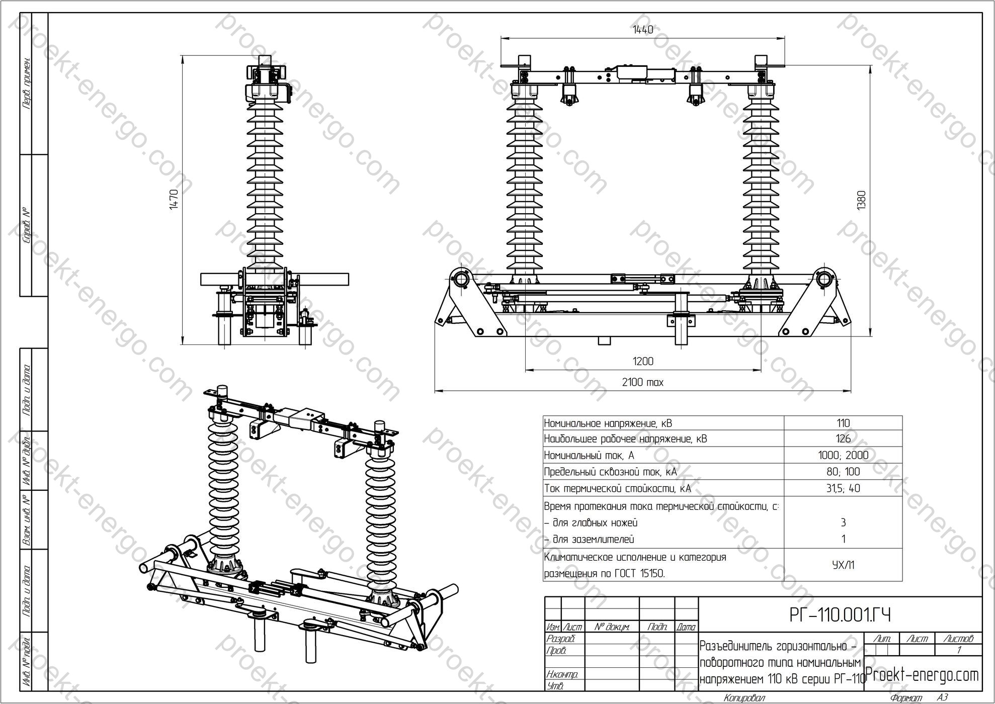
Technical data
| Rated voltage, kV | 220 |
| Highest system voltage, kV | 252 |
| Rated current, A | 1000; 2000; 3150 |
| Peak withstand current (Ip), kA | 100; 125 |
| Short-time withstand current (Ith), kA | 40; 50 |
| Duration of short-time withstand current, s - for main blades - for earthing switches |
3 1 |
| Creepage distance of external insulation, cm, not less than | 200 |
| Conductor tension in the horizontal plane (incl. wind), N, not less than | 800; 1000 |
| Minimum insulation clearances from live parts to various elements, mm (in air): - from live parts to earthed structures; - between live parts of different phases; - across the open contacts of a pole |
- 1800 - 2000 - 1800 |


Purpose and application
RDZ-220 is applied in outdoor switchyards of 110–330 kV substations: at line and busbar entries and taps, inter-section and inter-bus couplers, bypass (maintenance) busbars, and upstream of power transformers, autotransformers, reactors, shunt and series capacitor banks, and instrument transformers. The disconnector performs three key functions: safe isolation without load, provision of a visible break (visible air gap) for personnel authorization, and earthing of the disconnected section by integrated earthing switches. This makes RDZ-220 a core device for operational switching, selective equipment isolation and safe working conditions for maintenance staff.
Thanks to its resistance to climatic influences, high electrodynamic and thermal withstand, and unified design, RDZ-220 is used in transmission-level substations, generator output yards, high-power industrial incomers and special energy-infrastructure facilities. The disconnectors are compatible with common switchyard schemes: single/double busbar systems, busbar systems with sectioning, with bypass busbars, “bridge” schemes, etc.
Service conditions
Baseline environmental classification - EN/IEC 60721-3-4 (outdoor, non-weather-protected). Operating ambient temperature range from -60 °C to +40 °C. Operation is permitted with ice accretion up to 20 mm and wind speeds up to 40 m/s (no icing) or up to 15 m/s (with icing). The specified average humidity and wind pressure correspond to the above classification. Installation altitude up to 1000 m without correction of clearances; versions for higher altitudes with adjusted insulation level and increased creepage distance are available on request.
In the standard configuration RDZ-220 is designed for temperate and cold climates, solar radiation, temperature swings and freeze–thaw cycles. On request, reinforced designs are available for higher wind areas, heavy pollution (increased creepage by insulator profile and/or composite insulators), and seismic regions (reinforced supports, additional bracing, latching). The required seismic category and wind/icing regioning are to be defined by the substation project.
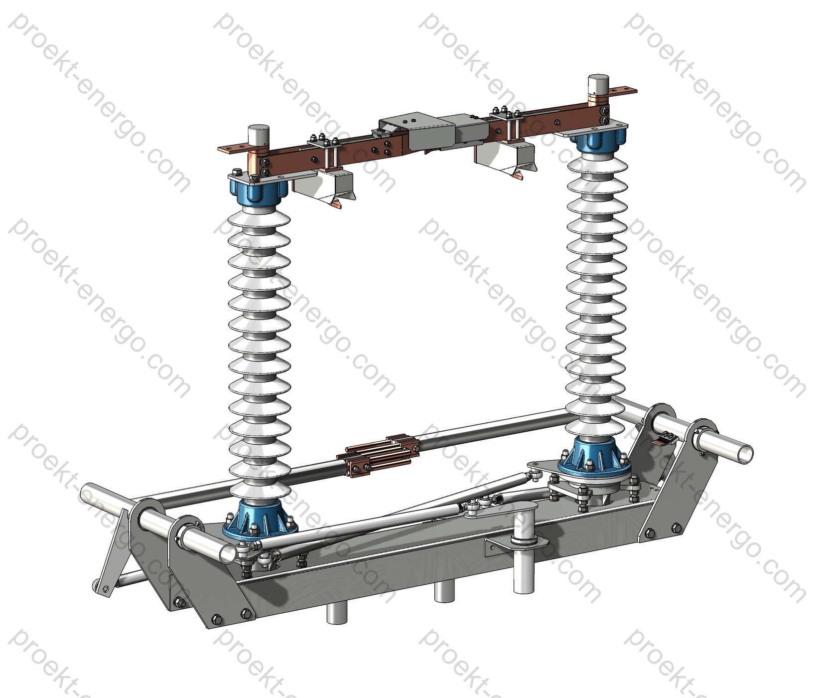
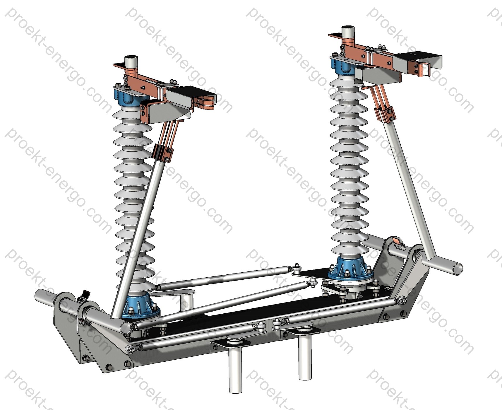
Design and construction
The two-post disconnector consists of two post insulators per pole, carrying the fixed and moving contacts with current bars and a rotating blade. Isolation is achieved by rotating the contact assembly about its axis, creating a visible inter-contact gap that allows visual confirmation of the open state. The design ensures high rigidity and stable gap geometry under wind and icing loads, as well as low losses at rated current. Current is transferred from the moving part by flexible multi-strand copper shunts with anti-corrosion coating.
The contact system is designed for high wear resistance: high-conductivity copper contact parts with silver plating, spring-loaded contact packs to compensate thermal expansion, and self-tightening effects at short-circuit currents. Frames and supports are made of low-alloy steel with hot-dip galvanizing; bolted joints are zinc-plated with corrosion-protection compounds. Bearing assemblies are sealed and grease-packed for long life; the kinematics include cardan shafts, levers, links and couplings with adjustable angles and play. Corona rings and shields are provided where corona discharge is possible.
Each pole can be equipped with earthing switches (on one or both sides of the main break), enabling different isolation and earthing modes of the protected sections. Phase spacing and connection elevations are adapted to the project: top/bottom connection, terminal orientation as required, selection of blade rotation direction and operating mechanism side. Maximum interchangeability of assemblies within the series is provided to unify maintenance and spares.
Materials and coatings of main assemblies
| Assembly | Material / design | Coating / features |
| Contact parts | High-conductivity copper | Silver plating, spring pressure |
| Flexible shunts | Multi-strand copper braids | Tin-zinc protective coating |
| Frames / supports | Low-alloy steel | Hot-dip galvanizing |
| Insulators | Porcelain / composite on request | Creepage per pollution level |
| Kinematics | Steel / bronze, sealed bearings | Long-life lubrication |
Safety and interlocks
RDZ-220 is equipped with mechanical interlocks preventing operation of the earthing switch when the main disconnector is closed and vice versa. Provision is made for padlocks on handles and for key interlocks (key-sequence) to interface with switchyard doors and adjacent apparatus mechanisms. Positions “Closed / Open / Earthed” are indicated by mechanical position indicators on the mechanism and on each pole; for remote signals, limit switches (at least two per position) and/or inductive sensors are available. The design excludes inadvertent movements due to wind and vibration; the operating linkages use locking elements, double latches and adjustable stops.
With the PD-14 motor operator, electrical interlocking and inter-mechanism logic are implemented: closing inhibition under position mismatch, position self-diagnostics, local/remote control with local priority, and the ability to take the drive in/out of service. The motor-operator enclosure is metallic, outdoor-rated, gasketed, with anti-condensation heating and entries for power and signal cables. Safety nameplates and points for attaching portable earthing leads (per project) are provided for personnel protection.
Versions and options
The RDZ-220 series includes versions by rated current (1000; 2000; 3150 A) and short-circuit withstand (thermal 40/50 kA, peak 100/125 kA). Options include one or two earthing switches per pole, right/left mechanism location, blade rotation direction, top/bottom terminals, corona rings/shields, porcelain or composite insulators, increased creepage distance for polluted areas, reinforced supports for high wind/icing loads and seismic designs. Optional accessories - position sensors, operation counters, localized heating of assemblies, stainless fasteners, protective contact compounds for harsh environments, cable glands with sealing.
Standards compliance
Design and manufacture comply with applicable requirements for 220 kV disconnectors. International standards applied: IEC 62271-102 (Disconnectors and earthing switches), IEC 62271-1 (Common specifications), IEC 60815 (Selection and dimensioning of high-voltage insulators for polluted conditions), IEC 60168 (Tests on indoor and outdoor post insulators of ceramic material or glass). Environmental classification per EN/IEC 60721-3-4 (outdoor; non-weather-protected). On request, documentation can be aligned to project-specific sections of the IEC 62271 series.
Scope of supply and related equipment
Typical scope of supply: disconnector poles assembled, support structures, PRG-6 manual mechanism or PD-14 motor operator (on request), cardan and link drives, fastening kit, flexible shunts, product passport and operating manual, data sheet, installation drawing, spare-parts list. For motorized versions - a local control cabinet with terminals for power and signal cabling, a set of limit switches and auxiliary contacts. Related equipment - CTs/VTs (per project), surge arresters, busbars, connectors, flexible links, bus support insulators, transposition inserts.
Installation and maintenance requirements
Installation is performed in accordance with the substation design, observing phase-to-phase and phase-to-earth clearances, connection elevations and service zones. Supports are mounted on foundations ensuring the specified elevations and stability under wind/icing loads. Kinematic linkages are installed without skew, respecting the design angles and clearances, followed by adjustment and checking of all positions and interlocks. Maintenance includes periodic inspection of contact surfaces, tightening of bolted joints, checking flexibility of shunts and condition of protective coatings, bearing lubrication (if specified), and verification of limit switches and indication.
Co-operation with contractors, equipment manufacturers and investors
We offer comprehensive cooperation to organize manufacturing of RDZ-220 disconnectors at your production site. The model includes transfer of the design-documentation package, process route and norms, selection of reliable suppliers (insulators, forgings/castings, flexible shunts, drive enclosures, galvanized steelwork), start-up support, production readiness audit and staff training. Critical assemblies (contact systems, cardan drives, earthing-switch kits) can be supplied by us to accelerate product mastering and mitigate risks in key components.
For investors, a staged entry model is available: from one-off batches for specific projects to stable serial production with localized procurement and service. During preparation, we jointly define equipment, tooling and instruments, identify bottlenecks, and develop method statements and an implementation schedule. For installation contractors, service contracts are available for supervision, commissioning, warranty support and rapid restoration under emergency conditions.
Documents
We prepare a complete set of design and O&M materials sufficient for independent manufacture and production set-up. The package includes: BOMs and purchase lists, assembly and part drawings, kinematic and interlocking schemes, external connection diagrams, cable and wire lists, installation drawings and general arrangements. 3D models are provided in SolidWorks and neutral exchange formats STEP/Parasolid; 2D drawings in DWG/DXF for AutoCAD. Additionally, we provide a “zero” tender set (descriptions, questionnaires, compliance matrices), test programs and procedures, transport and storage instructions, O&M regulations, typical lubrication and fastening charts, as well as passport and data-sheet templates.
Why work with us
- Faster time-to-production: documentation tailored to your shop capabilities, avoiding redundant operations and rework.
- Lower cost: optimized list of purchased assemblies and alternative suppliers for critical items.
- Operational reliability: proven design solutions for harsh climates, enhanced contact system and reinforced kinematics.
- Full engineering support: from supervision and adjustment to failure analysis based on field experience.
For additional information on RDZ-220 disconnectors please contact: inbox@proekt-energo.com
PDF – Download technical information on RDZ-220 disconnectors