- We offer co-operation on replacement of old installed equipment on equipment at substations with new equipment produced at your factory. We have a large database of documentation for old, end-of-life equipment, and we will adapt your products to replace the old.

- Design of substation equipment in accordance with the technical specifications.

- Design documentation for the manufacture of electrical equipment.

- 3-D models, product drawings, BOM.

- Preparation of technical documentation for participation in tenders.

- Preparation of preliminary standards for material consumption for cost calculation..

- Consulting on projects.

..since August 1998

Proekt-Energo

Area of activity:

- Design of low-voltage, middle-voltage and high-voltage electrical equipment of substations for voltages of 0.4 - 220 kV.
- Development of working documentation in accordance with the technological capabilities of the plant.
- Preparation of preliminary technical documentation for participation in tenders for the supply of equipment.
- Consultations on project approvals.
- Supporting the production of equipment at the plant.

Specialization:

- Switchgear for indoor and outdoor installation for voltages of 6, 10, 20, 35 kV.
- Air-insulated secondary switchgears AIS for voltages 6, 10 kV.
- Complete transformer substations CTS for voltage 10 - 220 kV.
- Disconnectors for voltage 0.4 ... 220 kV.
- Drive to disconnectors.
- Replacement of withdrawable elements and switches in existing switchgear (Retrofit).
- Low-voltage switchgears for voltage 0.4 kV.
- DC 600V switchgears RU-600.

RVFZ-10 (RVF-10) Indoor AC Disconnector

The RVFZ-10 (RVF-10) indoor AC disconnectors are used to isolate, without load, individual sections of 6 or 10 kV three-phase networks and to earth de-energized sections by means of built-in fixed earthing blades. Unlike RVZ units, RVFZ uses through-wall (bushing) insulators instead of post insulators, which makes it convenient to bring the conductor in from one side of a partition and take it out from the other without additional wall bushings.
Typical applications:
- Package transformer substations (KTP);
- Single-front metal-clad cubicles (KSO);
- Metal-clad MV switchgear (KRU);
- Outdoor complete switchgear KRUN;
- Mobile package transformer substations;
- Main distribution boards (MDB);
- Capacitor banks;
- Incoming and distribution panels.
Product range:
- RVFZ-10/400 - disconnector rated at 400 A;
- RVFZ-10/630 - disconnector rated at 630 A;
- RVFZ-10/1000 - disconnector rated at 1000 A;
- RVFZ-10/2000 - disconnector rated at 2000 A.
The disconnector is supplied as a three-pole unit with earthing switches (RVFZ-10) or without earthing switches (RVF-10). Mechanical interlocking prevents hazardous mis-operation:
- blocks the earthing switch from closing when the main blades are closed;
- blocks the main blades from closing when the earthing switch is closed.
Rotation of the operating shafts of the main circuit and the earthing switch is manual, via PR series hand-operated mechanisms. RVFZ disconnectors are available up to 2000 A.
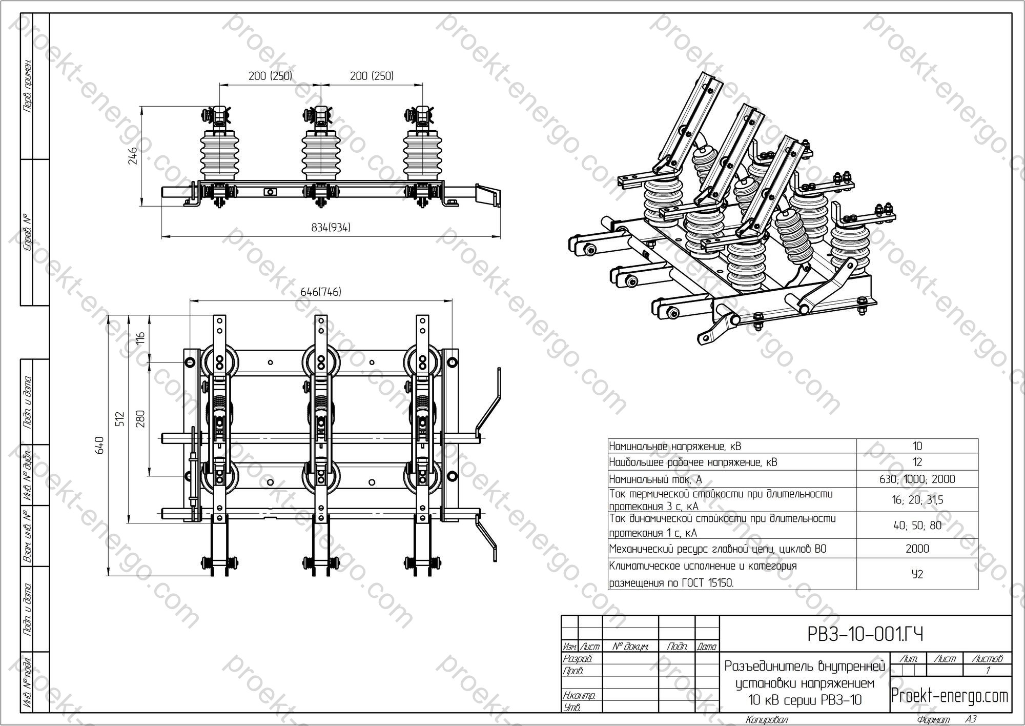
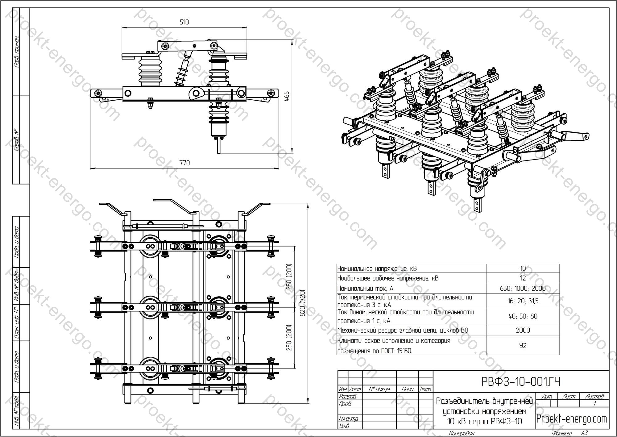
Technical data

Rated voltage, kV 6; 10
Maximum system voltage, kV 7.2; 12
Rated current, A 400; 630; 1000; 2000
Rated short-time withstand current (3 s), kA rms 16; 20; 31.5
Rated peak withstand current (kA peak) 40; 50; 80
Mechanical endurance (main circuit), O–I cycles 2000
Environmental conditions (per EN/IEC 60721-3-3) Indoor, weather-protected (IEC 60721-3-3)

Purpose and application

RVFZ-10 (RVF-10) is intended for fast sectionalizing and reconfiguration of 6–10 kV MV distribution schemes, for providing a visible isolating gap during operational switching, for fault localization and for establishing a safe work zone. By using through-wall bushings, current-carrying parts can be arranged on opposite sides of a cabinet/cubicle partition, which simplifies KRU/KSO layouts and reduces the number of transition joints. The disconnectors are used in busbar sections, incomers/feeders, connections to transformers, reactors, capacitor banks, as well as in standby supplies and bus-tie/bypass sections. In sectionalizing cubicles the device enables quick network reconfiguration (source transfer, bus-tie/bus-reserve) without tripping adjacent feeders.

Compared with classic RVZ (post-insulated) designs, the RVFZ shaped arrangement offers more flexible layouts, reduces module dimensions, simplifies bus/cable routing and lowers the number of potential hot-spots by cutting intermediate bolted joints.

Service conditions

Baseline environmental classification - EN/IEC 60721-3-3 (indoor, weather-protected). Other classes on request. Rated frequency - 50 Hz; installation altitude - up to 1000 m above sea level without insulation derating (apply altitude correction above 1000 m according to general requirements for medium-voltage switching devices). Degree of protection for the device without an enclosure - IP00 (in a cubicle, the protection degree is that of the KRU/KSO enclosure). Acceptable ambient conditions - industrial sites free from aggressive gases and conductive dust beyond normal levels, and vibration not exceeding the limits specified in the product data. Operation is indoors with temperature and humidity maintained per the project and the switchgear operating documentation.

The disconnector is designed for standard mechanical impact categories applicable to MV switchgear. Clearances and creepage distances are sized for the 6(10) kV class; for locations with elevated pollution, humidity or at altitudes >1000 m, increased creepage/extra insulation measures are recommended. The permissible temperature range and other climatic factors are specified to EN/IEC 60721-3-3; extended options are available on request.
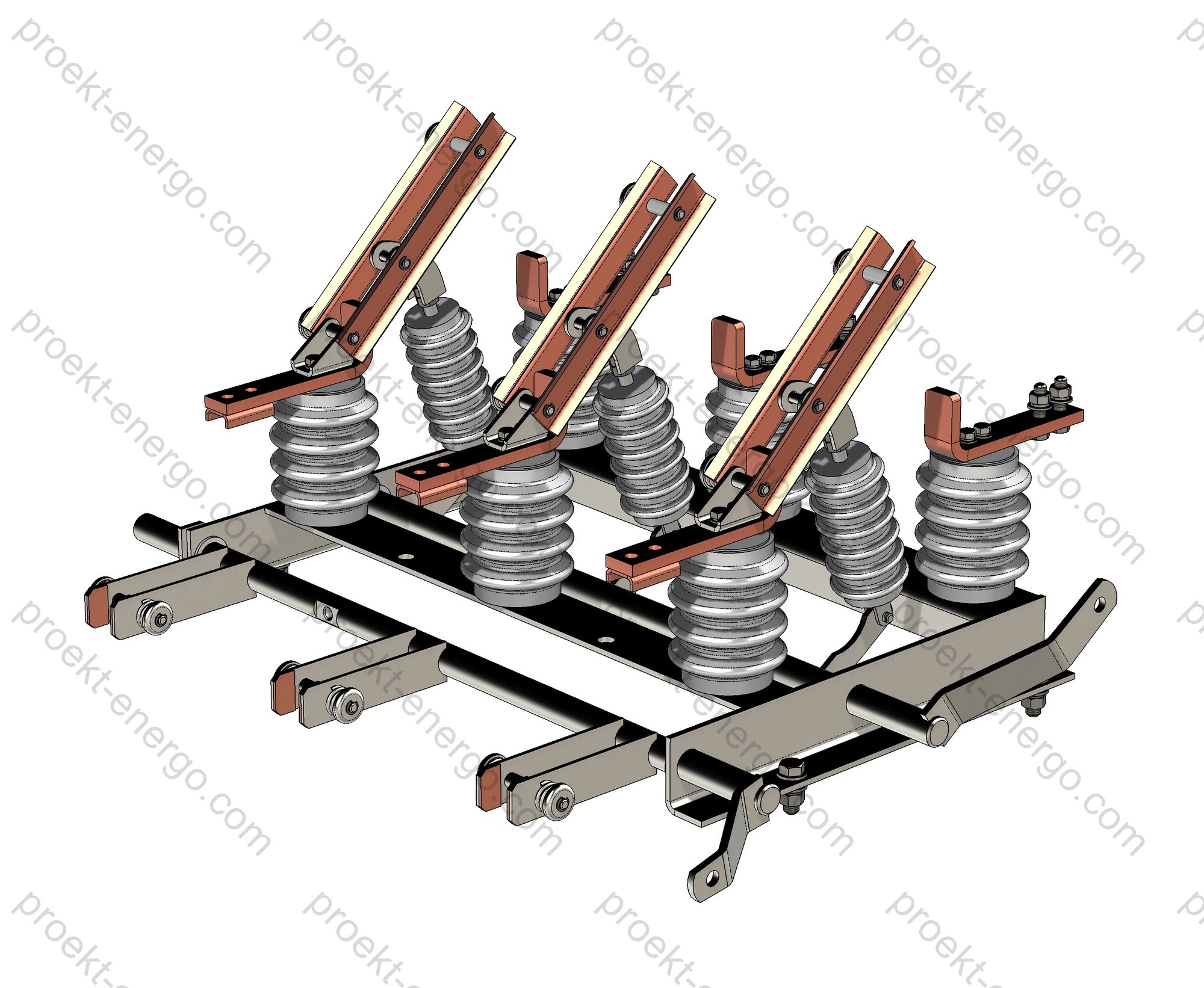
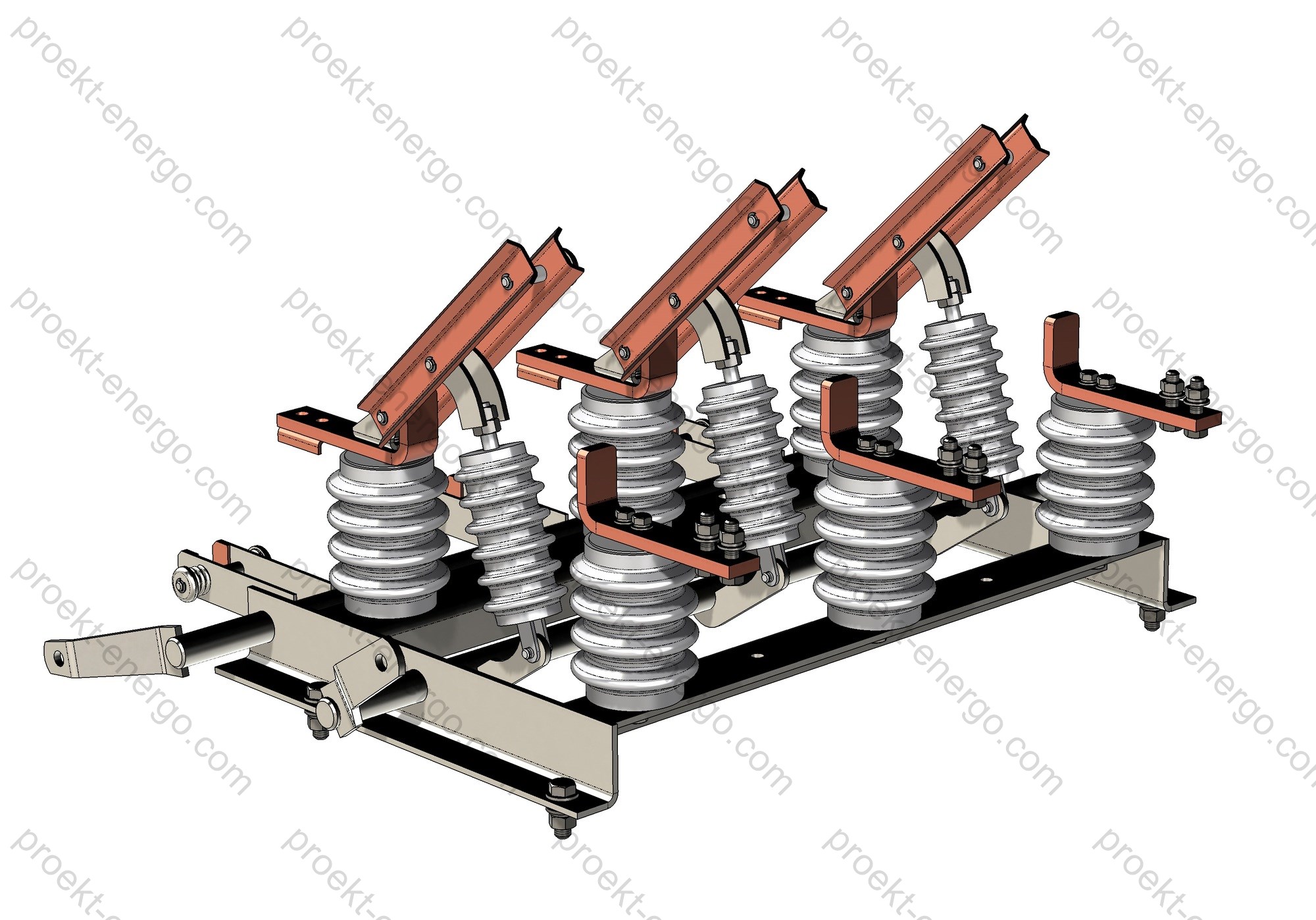
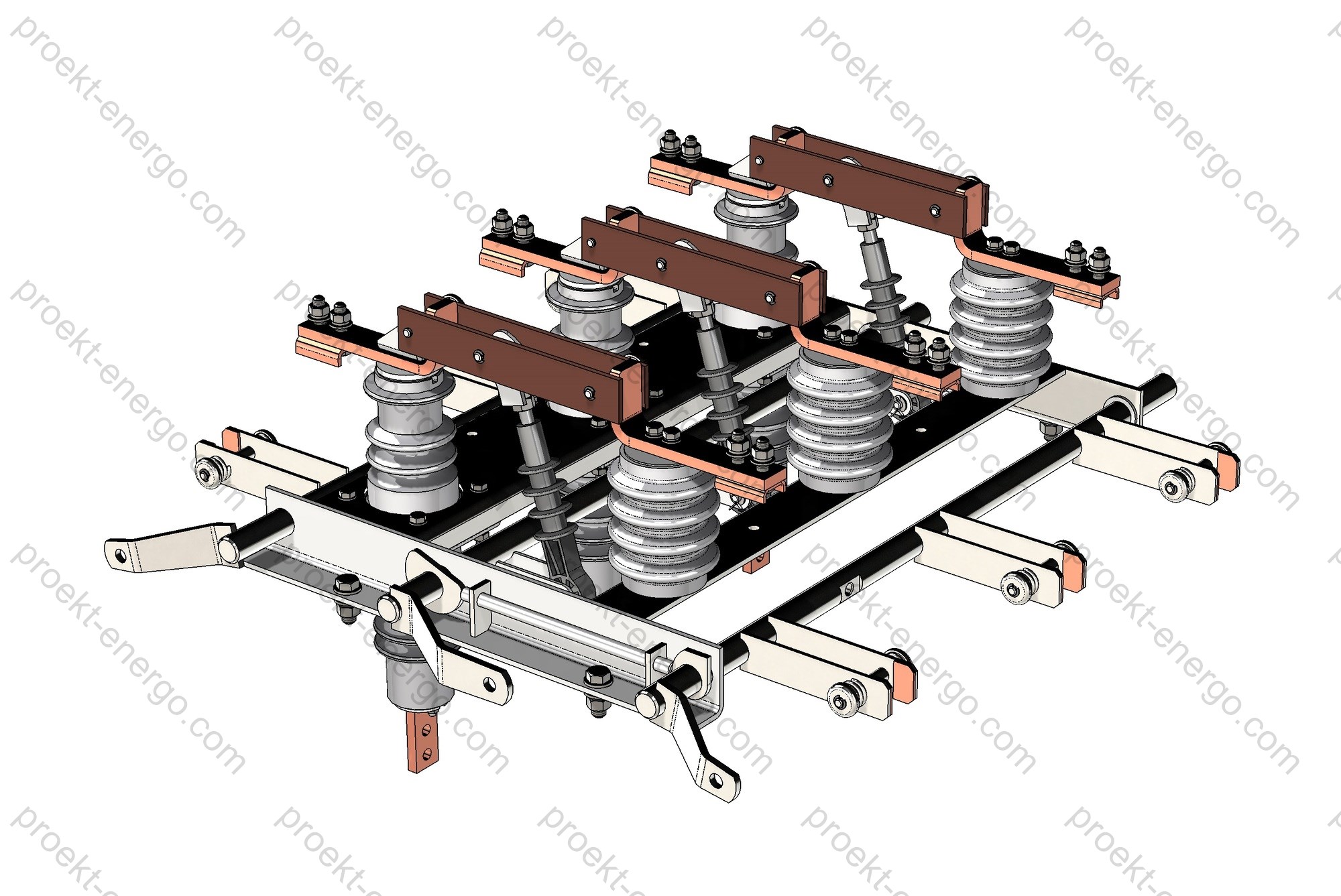
Design and layout

RVFZ-10 is a three-pole vertical-break disconnector on a welded base frame. Each pole includes: through-wall bushing insulators (on the hinge or jaw side, depending on the version), a moving blade, a contact system (fixed and moving contacts with high specific pressure), current bars and mounting hardware. Through-wall bushings allow current entry/exit across cubicle partitions, which is convenient for separating the busbar and cable compartments. Contact surfaces typically feature hardening and/or silver plating to reduce contact resistance and improve cyclic endurance. Additional pressure elements and springs maintain contact force throughout service life.

Earthing blades (for RVFZ versions) can be fitted on the hinge side or on the jaw (fixed contact) side to match the cubicle layout. Positions are positively defined with visual indication (“ON/OFF”). The three poles are mechanically synchronized. Drive torque is transmitted via operating shafts with a linkage mechanism. The design provides connection pads for bars/flexible links and holes for bolted joints (sizes agreed at order). Overall dimensions and inter-pole spacing are selected to suit the current rating and the space constraints of the cubicle, simplifying integration into various KRU sizes.

Manual operator - PR series (type PR-10 or equivalent), with door- or side-mounting. Options include interlock hardware on the operator (position latching, padlocking points) and auxiliary position switches for SCADA indications. On request, a motor operator can be supplied for remote control.

RVZ vs. RVFZ layouts (to aid selection)

Parameter RVZ (post insulators) RVFZ (through-wall bushings)
Conductor entry/exit From the front side of the cubicle In and out on opposite sides of a partition without extra wall bushings
KRU/KSO layout Conventional, more bus joints Simplified bus/cable routing, fewer transition joints
Module dimensions Typical Often smaller thanks to “through” connections
Typical applications Bus sections, incomers/feeders Through-partition sections (inter-compartment, KRUN, KTP, etc.)

Safety and interlocking

The device provides a visible isolating gap and employs mechanical interlocks to prevent hazardous operations. The operator interlock prevents closing the earthing blades when the main circuit is closed, and blocks closing the main blades when the earthing switch is closed. Padlocking points are provided in the open position, as well as mounting for auxiliary limit switches to indicate “ON/OFF/EARTHED”. Integration into the cubicle key-interlock system (cable/key schemes) is supported. Protective screens and barriers around the contact area prevent accidental contact with live parts during maintenance.

Versions and options

RVFZ-10 is supplied in several current ratings (400; 630; 1000; 2000 A) according to continuous load and cooling conditions. The earthing-blade arrangement is selected by side (hinge side or jaw side); dual earthing (both sides) can be provided for special layouts. By agreement, variants with modified inter-pole spacing, shaft orientation, operator position, sets of auxiliary contacts and signaling switches are available. On request, mounting kits for different bar/cable types and transition bars can be supplied.

Version Rated current Earthing blades Operator Features
RVF-10/400 400 A - PR Compact for KTP/KSO
RVFZ-10/630 630 A Top or bottom PR Optimal for 6–10 kV KRU
RVFZ-10/1000 1000 A To project PR / (optional motor operator) Enhanced thermal capability
RVFZ-10/2000 2000 A To project PR / (optional motor operator) For bus sections and high-load feeders

Standards compliance

The design and testing of the disconnectors comply with applicable MV switchgear standards. Depending on the destination market and project requirements, the following standards (latest editions) are applied:

  • EN/IEC 62271-102: AC disconnectors and earthing switches (including Amd 1);
  • EN/IEC 62271-1: High-voltage switchgear and controlgear - Common specifications;
  • EN/IEC 60721-3-3 and EN/IEC 60721-3-4: Environmental conditions (classification for weather-protected and non-weather-protected locations);
  • DSTU EN IEC 62271-102: National adoption for Ukraine (for deliveries to the Ukrainian market).

Manufacturing cooperation

For large batches we arrange cooperation with specialized manufacturers and contractors to perform machining, bar work, subassembly, painting and quality control. This shortens time-to-series, reduces development costs and enables fast adaptation to the project requirements and the customer’s manufacturing capabilities. Subassemblies and connection kits can be supplied for integration into third-party KRU/KSO platforms.

Project and manufacturing documentation package

For each project we provide a documentation set for design, process and production preparation: overall and connection drawings, assembly drawings, bills of materials, purchase lists, 3D models (Parasolid, STEP), and CNC exchange files (DXF, DWG). On request - adaptation to the customer’s CAD (AutoCAD, SolidWorks), operating documentation, test programs and procedures, product data sheets and certificates. Documentation can be aligned with the standards and quality practices used in the project.

We offer documentation for manufacturing RVFZ-10 disconnectors:

- Preliminary technical documentation for tender participation. We will prepare the information required to assess manufacturability against tender requirements and questionnaires.
- Working drawings, 3D models and other documents required to manufacture RVFZ disconnectors at your facility. If you do not plan to make parts in-house, we will help outsource them. Final assembly and fitting can be done at your site.
- All documentation can be adjusted to the project requirements and to your plant’s process capabilities.
- If other manufacturers’ equipment is installed at the substation, we will prepare documentation to produce matching equipment to complement it.

Benefits of working with us:

- No need to maintain a large team of senior engineers - you receive a complete manufacturing package that can be handled by a mid-level engineer.
- No need to build pilot prototypes - our experience allows launching series production directly.
- Your staff will receive guidance on all nuances of RVFZ-10 manufacturing when working to our documentation.

For additional information on RVFZ disconnectors please contact: inbox@proekt-energo.com

…and, as is commonly known, an error made at the design stage costs 10 times more in manufacturing and 100 times more in operation.

PDF - Download technical information on RVFZ-10 disconnectors

pdf

RVZ-10 (RV-10) Indoor Disconnector

RVZ-10 (RV-10) indoor AC disconnectors are used for making and breaking, without load, individual sections of medium-voltage networks rated 6 or 10 kV, as well as for earthing de-energized sections by means of fixed earthing blades. Applications:
- Prefabricated transformer substations (KTP);
- Unit switchgear cubicles with single-sided service (KSO);
- Metal-enclosed switchgear (KRU);
- KRUN;
- Mobile prefabricated transformer substations;
- Main distribution boards (MDB);
- Capacitor banks;
- Incoming and distribution panels.
Disconnector range:
- RVZ-10/400 – disconnector rated current 400 A;
- RVZ-10/630 – disconnector rated current 630 A;
- RVZ-10/1000 – disconnector rated current 1000 A;
- RVZ-10/2000 – disconnector rated current 2000 A.
The disconnector is manufactured as a three-pole unit with fixed earthing switches (RVZ-10) or without earthing switches (RV-10). Mechanical interlocking prevents incorrect operations: the earthing switch cannot be closed when the main blades are closed; the main blades cannot be closed when the earthing switch is closed. Rotation of the operating shafts of the main circuit and the earthing switch is manual - via PR manual operating mechanisms. Disconnectors are produced with rated currents up to 2000 A.

Technical data

Rated voltage, kV 6; 10
Highest voltage for equipment (Um), kV 7.2; 12
Rated current, A 400; 630; 1000; 2000
Rated short-time withstand current (3 s), kA 16; 20; 31.5
Rated dynamic withstand current (1 s), kA 40; 50; 80
Mechanical endurance of main circuit, O–C operations 2000
Climatic design and location category per GOST 15150 U2

Purpose and application

RVZ-10 (RV-10) is a three-pole vertical-break (swing-link) switching device that provides a visible isolating gap and ensures safe operational isolation and earthing of medium-voltage networks 6–10 kV. The disconnector is intended for:
• localization and selective outage of individual feeders, busbar sections and connections in KSO/KRU;
• creating maintenance gaps with visual indication of blade position;
• safe connection and testing of standby lines, busbar sectionalizing, isolation of metering and measurement nodes;
• bus-coupler and bus-reserve schemes, as well as switching capacitor banks without load;
• earthing of de-energized sections by built-in fixed earthing blades (for RVZ versions).

Thanks to its modular layout and universal connection dimensions, RVZ-10 series disconnectors fit most standard KSO cubicles (single- or double-sided service), metal-enclosed switchgear KRU/KRUN, and complete substations (fixed and mobile) both at 6 kV and 10 kV. The design is oriented for integration with widely used PR manual mechanisms and three-position schemes “ON - OFF - EARTHED”, which simplifies fleet unification and reduces total cost of ownership.

Operating conditions

Climatic design - U2 according to GOST 15150, for operation in temperate climates indoors with free air access or under a shelter. Location - category 2. The insulation, contact assemblies and support insulators are designed for the specified service and test stresses for switchgear with voltage classes 6 and 10 kV at 50 Hz. Installation is permitted up to 1000 m above sea level without recalculation of insulation levels; for elevations above 1000 m the dielectric requirements are addressed by project documentation (in line with general provisions for MV switching devices). The disconnectors are intended for 50 Hz networks with standardized temperature, humidity and dust levels within the location category, and for operation inside KSO/KRU metal cubicles with natural ventilation. Screwed and pinned joints are protected against self-loosening under vibration, and moving parts are designed for long service without disassembly, subject to periodic maintenance.

Layout and design solutions

The RVZ-10 disconnector is a three-pole assembly on a common welded frame. Each pole includes:
• support (or bushing - in the RVFZ variant) insulators of increased mechanical strength;
• a swinging current-carrying blade made of copper or aluminum alloy with anti-oxidation coating; contact surfaces may be galvanically hardened (e.g., silver-plated) to reduce contact resistance;
• fixed and moving separable contacts with multi-finger spring packs providing stable contact pressure throughout service life;
• main-circuit shaft and earthing-switch shaft (for RVZ) with synchronizing linkage and positive end-position latches;
• mechanical end-stops, position indicators (“ON”, “OFF”, “EARTHED”) with the option to transmit status to the cubicle mimic diagram.

The three-pole unit is mounted on a base (frame) with standardized fixing holes for installation in typical KSO/KRU frameworks. Layout variants allow the earthing switch to be on the separable (fixed) side or on the hinged (moving) side - depending on the connection scheme. The design allows left- or right-hand mechanism placement and compatibility with standard cubicle transmissions. Contact systems are rated for the specified short-time and dynamic withstand currents; contact resistance remains stable due to a self-wiping effect during operation and optimized blade geometry. Multi-point contact sockets and flexible connectors are used at high-current locations.

The PR manual three-position mechanism, installable on the cubicle door, provides:
- “ON” (main blades closed, earthing switch open);
- “OFF” (visible isolation of the main circuit);
- “EARTHED” (main blades open, earthing blade closed).
The kinematics exclude simultaneous closure of the main circuit and the earthing switch. Provision is made for padlocks (up to 3 pcs) for organizational lockout. Position is shown by mechanical indicators and/or by a microswitch for auxiliary signalling to SCADA.

Safety and interlocks

The interlocking system prevents hazardous operations: with the main blades closed it is mechanically impossible to close the earthing switch, and vice versa - with the earthing switch closed the main blades cannot be closed. Mechanical stops prevent incomplete make/break. A visible isolating gap and reliable position latching improve personnel safety during switching and maintenance. The mechanism has holes for padlocks and seals, enabling lockout/tagout as required by work permits. The design withstands short-circuit forces within the rated short-time and peak withstand values; earthing components have thermal and mechanical margins. On request, additional shrouds and barriers can be installed, as well as key interlocks with other apparatus (e.g., a load break switch mechanism) to enforce the required sequence of operations.

Versions and options

The RVZ-10 series includes basic and extended versions for standard cubicles and special applications:
• RV-10 - without earthing switch (main circuit only);
• RVZ-10 - with one fixed earthing switch (on the separable side or on the moving side);
• RVZ-10 (double-earthing version) - per project for special sectionalizing tasks;
• version with bushing insulators (RVFZ analogue) - for applications requiring enhanced wall-through insulation;
• left/right mechanism, extended linkages, versions for various phase spacings;
• remote mechanical position indicators, electrical limit switches, contact for “abnormal” blade position;
• supply with flexible busbars/bus bridges and a set of mounting hardware;
• protective covers for live parts and local shields. Installation and connection

Standards compliance

The design and test requirements are aligned with applicable international and national standards for AC disconnectors and earthing switches. The following standards are taken into account during design and testing:
• IEC 62271-102 - “High-voltage switchgear and controlgear - Part 102: Alternating current disconnectors and earthing switches”;
• IEC 62271-1 - “High-voltage switchgear and controlgear - Part 1: Common specifications”;
• IEC 62271-200 - “Metal-enclosed switchgear for rated voltages above 1 kV” (as applied to the cubicles housing the device);
• GOST R 52726-2007 - “AC disconnectors and earthing switches above 1 kV and their operating mechanisms”;
• GOST 1516.1 - “AC equipment from 3 to 500 kV. Insulation withstand requirements”;
• GOST 15150 - “Climatic design and location categories” (U2).

Scope of supply and documentation

Typical supply set includes: three-pole disconnector on a frame (per agreed configuration), PR manual mechanism with linkages, mounting hardware set, data sheet/form, operation manual, and a set of safety posters/labels (as per project). On request: busbar connection kit (flexible bars, bus bridges), additional shrouds for live parts, position microswitches, mechanical indicators, removable lock-keys. To speed up integration, working design documentation and 3D models in popular formats are available.

Document / modelFormatPurpose
Set of working drawings DWG, DXF Part manufacturing and assembly, fitment into KSO/KRU cubicles
3D models of units and assemblies STEP, Parasolid, SLDPRT/SLDASM Dimensional and kinematic coordination, digital mock-up
Bill of materials (BOM) XLSX, PDF Procurement planning, costing
Data sheet / O&M manual PDF Operation and maintenance

Engaging contractors and partnership

We are open to cooperation with manufacturers of electrical equipment, design and installation companies, as well as investors interested in organizing serial production of 6–10 kV disconnectors. We provide preliminary and working documentation packages and technical support for ramp-up: material selection, machining and assembly recommendations, sourcing of cast/forged parts, reference samples. Documentation transfer is accompanied by design-engineer consultations. Adaptation of drawings to your manufacturing capabilities and regulatory requirements is available. We help arrange the cooperation chain: metalworking, electroplating, insulator manufacture, assembly and routine tests. By agreement, we provide personnel training, shop audits and implementation of QC procedures.

Benefits of working with us:

- No need to maintain highly specialized engineering staff - you receive a complete documentation set for the product that can be handled by a mid-level engineer.
- No need to build pilot samples - our experience allows launching serial batches straight into production.
- Working to our documentation - your team will receive guidance on all nuances of manufacturing RVZ-10 disconnectors.
- Support at every stage - from preliminary short-circuit and thermal calculations to routine tests and series quality control. Checklists are provided for mechanism setting, contact pressure adjustment, templates for blade-position checks, and operating instructions.

For additional information on RVZ-10 disconnectors, please contact: inbox@proekt-energo.com

...and, as is well known - an error made at the design stage results in 10× costs in manufacturing and 100× in operation...

PDF - Download technical information on RVZ-10 disconnectors

pdf

RVR-20/8000; RVRZ-20/8000 Indoor Vertical-Break Disconnector

The RVR-20/8000 and RVRZ-20/8000 indoor disconnectors are intended for isolating and reconnecting de-energized sections of an electric circuit in medium-voltage systems while the installation remains live (no load current), as well as for earthing such sections by means of fixed earthing switches.
By design, the vertical-break type disconnectors are manufactured in single-pole execution.
RVR units are supplied without an earthing switch; RVRZ units are supplied with an earthing switch on either the separable-contact side or the non-separable-contact side.
RVR/RVRZ disconnectors consist of a base frame, support insulators, contact system, pull-rod (operating) insulator and earthing switches. A drive shaft with levers mounted on the frame operates the moving blades. If earthing switches are fitted, one or two additional shafts are provided to operate them, together with a mechanical interlock that prevents closing the earthing switch when the main blades are closed, and vice versa. The insulation set comprises support and operating insulators. The contact system comprises fixed copper contacts and moving copper blades. To reduce opening and closing torque, a contact-pressure relief mechanism is used (cam and latching assemblies). The earthing switches comprise a copper bar fixed to steel uprights welded to the earthing-switch shaft. When the earthing switch is closed the bar enters lamellar contacts mounted on the lower shelves of the fixed main contacts. Contact pressure in the axial and separable main contacts and in the earthing lamellae is provided by springs.
RVR/RVRZ disconnectors are intended for operation in indoor switchgear under the following environmental conditions:
– altitude not exceeding 1000 m;
– maximum ambient temperature +40 °C;
– minimum ambient temperature -45 °C;
– relative humidity 80% at +20 °C.

Technical data

Rated voltage, kV 20
Highest voltage for equipment (Um), kV 24
Rated current, A 8000
Short-time withstand current (3 s), kA 100
Dynamic (peak) withstand current (1 s), kA 250
Mechanical endurance of main circuit, O–C cycles 2000
Environmental classification (EN/IEC 60721-3-3) EN/IEC 60721-3-3

Purpose and application

RVR-20/8000 and RVRZ-20/8000 are high-current, vertical-break disconnectors for 20 kV medium-voltage systems with an exceptionally high rated current up to 8,000 A. They are used to isolate and provide a visible break in busbars and feeders without shutting down the entire switchgear lineup. Typical applications include busbar sectioning in metal-enclosed switchgear (KRU) and gas-insulated switchgear (GIS), transformer incomers/outgoers, bypass and maintenance links at primary substations, high-current auxiliary bus systems in power plants and metallurgical facilities, and busduct nodes in industrial power supply centers.
The disconnectors may be operated under voltage without load current and, when equipped with motor drives and interlocks, provide safe earthing of the isolated sections prior to work. The single-pole design allows flexible arrangement on site: building three-phase groups, bus sectioning, or adding bypass blades.

Service conditions

Designed for indoor installation at electrical stations and substations free from conductive dust, aggressive gases and vapors, in non-hazardous environments. Environmental classification per EN/IEC 60721-3-3 (stationary use at weather-protected locations). Operating ambient temperature from -45 °C to +40 °C; relative humidity up to 80% at +20 °C; installation altitude up to 1000 m above sea level. Seismic capability can be provided by project when installed on appropriate foundations. The degree of protection for live parts is determined by the switchgear/cubicle design; drives and interlocks are typically no less than IP20/IP21. Applicable for use in compartmentalized switchgear cells (KSO), metal-enclosed switchgear at 6–20 kV, and special bays of primary substations with forced ventilation. High current duty requires superior contact quality and cooling: low contact resistance is ensured and permissible temperature rise is calculated considering natural convection and busbar thermal conductivity. For dusty or humid rooms, periodic inspection of bolted joints and torque control per maintenance schedule is recommended.

Layout and construction

The disconnector is built on a welded steel frame with anti-corrosion coating. Support insulators (porcelain or composite) provide high mechanical strength and creepage distance suited to the site pollution level. The moving assembly is a vertical-break copper blade with silver-plated contact surfaces. Blades are rigidly linked to the drive shaft via a lever-cam mechanism that provides a fast break and stable contact pressure in the CLOSED position while reducing the drive torque during operation.

Fixed contacts are multi-lamellar, spring-loaded (copper alloy lamellae with silver coating) for reliable performance at 8,000 A continuous current and short-circuit duties. Busbar connections are via flat copper terminals drilled for standard hardware; flexible copper shunts can be supplied to compensate thermal expansion. Reduced heating is achieved by enlarged contact areas, optimized blade/lamella geometry and minimizing separable joints in the current path. The contact-pressure relief mechanism (cam/latch) decreases wear and operating effort while maintaining the required pressure in service.

The earthing switch (RVRZ versions) is mounted on the common base and operated by a dedicated shaft. Its copper bar engages lamellar contacts installed on the lower shelves of the main fixed contacts, ensuring low resistance and high making/withstand capability under short-circuit conditions. Shafts of the disconnector and earthing switch are equipped with local position indicators «ON/OFF/EARTHED» and allow mounting of limit switches for SCADA signaling.

The kinematic system is rated for a mechanical endurance of at least 2,000 O–C cycles while maintaining contact pressure and spring integrity. All fasteners are secured against loosening (cotter pins/locking elements). Corrosion protection includes powder-coated frame parts and tin/silver galvanic coatings on current-carrying parts to minimize contact resistance and oxidation.

Safety and interlocking

An independent mechanical interlock is implemented between the main blade and the earthing switch: closing the earthing switch with the disconnector closed is prevented, as is closing the main blades with the earthing switch closed. The interlock is shaft-mounted with positive mechanics and allows sealing/padlocking. For integration into safety schemes, the following are provided:

  • electrical interlocks (limit switches with changeover contacts for control circuits);
  • key interlocks (on request) to enforce the operating sequence;
  • local mechanical indication and provision for duplicate “DANGER - LIVE/EARTHED” tags;
  • travel stops and dampers to reduce impact loads.

Versions and options

The base range includes a version without earthing switch (RVR) and a version with earthing switch (RVRZ). Single-pole construction allows configuring three-pole groups using coupling rods and synchronizing shafts. Drives can be manual rotary or motorized with remote control. On request: mirrored earthing-switch location (left/right), terminal kits for various bus widths and flexible shunts, additional auxiliary contacts, and position sensors for SCADA integration.

Execution codeDescriptionApplication/notes
RVR-20/8000 Single-pole disconnector without earthing switch Bus sectioning, bypass links
RVRZ-20/8000-L Disconnector with earthing switch on the left (relative to drive) Maintenance earthing on feeders
RVRZ-20/8000-R Disconnector with earthing switch on the right (relative to drive) Optimized cubicle/chamber layout
… + MD With motor drive and remote control SCADA integration, logic interlocks
… + AC Additional auxiliary contacts (ON/OFF/EARTHED) Signaling, interlocking

Materials and endurance

AssemblyMaterial/coatingPurpose/features
Moving blade Copper, silver-plated contact surfaces Low contact resistance at 8,000 A
Fixed contact Copper-alloy lamellae, silver coating Stable pressure, short-circuit strength
Insulators Porcelain/composite, increased creepage distance Operation under high humidity/pollution
Frame/shafts Steel with powder coating/galvanized Corrosion resistance, rigidity
Springs Spring steel Maintaining contact force

Compliance with standards

Design and testing are oriented to the requirements for medium-voltage switchgear and controlgear:

  • IEC 62271-1 - Switchgear and controlgear, common specifications;
  • IEC 62271-102 - Alternating-current disconnectors and earthing switches;
  • IEC 62271-200 - A.C. metal-enclosed switchgear and controlgear rated 1–52 kV;
  • EN/IEC 60721-3-3 - Environmental classification, stationary use at weather-protected locations;
  • EN/IEC 60721-3-4 - Environmental classification, stationary use at non-weather-protected locations (if applicable).

Engaging manufacturers and contractors

We are open to cooperation with mechanical plants, switchgear OEMs, installation and service companies. We provide licensable working documentation for manufacturing RVR/RVRZ disconnectors at your facilities, including material specifications and standard process sheets. We assist in organizing production of sub-assemblies (bending and brazing copper bars, lamellar contacts, machining, surface finishing), and in conducting validation and type tests per program and procedures. For investors and developers we offer production localization support, supplier selection, cost modeling and equipment upgrades. For SCADA integrators - drive data sheets, limit-switch interfaces and signaling/control I/O.

Documentation supplied for design and manufacturing

On request we supply: 3D models (Parasolid, STEP), assembly/part drawings and BOMs (DWG/DXF), CAD assemblies for AutoCAD/SolidWorks, lists of purchased items and materials, interlock and kinematics schemes, installation & maintenance manuals, product passports and delivery specifications. Customization to a particular project is available (compartment size, bus width, drive orientation), as well as guided launch of a pilot production batch without building a prototype - based on proven solutions and thermal/electrodynamic calculations.

Benefits of working with us

– No need to maintain a large team of highly specialized engineers - you receive a complete manufacturing package that can be handled by a mid-level engineer.
– No need to build physical prototypes - our experience enables successful launch of serial batches directly from documentation.
– Working to our documentation, your team receives consulting on all nuances of RVR-20 assembly (layout, kinematics, contact-pressure control, interlock adjustment, test preparation).

For additional information on RVR-20/8000 and RVRZ-20/8000 disconnectors, please contact: inbox@proekt-energo.com

... and, as is well known, an error made at the design stage turns into 10× costs in manufacturing and 100× in operation...

PDF - Download technical information for RVR-20/8000; RVRZ-20/8000

pdf

RND-35 Double-Column Knife Disconnector (Center-Break), Outdoor, 35/36 kV

RND-35 series visible-break, center-break air-break switches (disconnectors) are intended for operational switching of de-energized 35/36 kV circuits and for earthing/grounding isolated sections when supplied with integrated earthing switches. The kinematics is a horizontal-rotary, center-break design: one or two rotating post insulators turn 90° to produce a clearly visible isolation gap and stable, high contact pressure. Each pole uses a double-column scheme: the blades (moving knives) are mounted on the upper flanges of the post insulators; the separable (female) contact is protected by a hood for reliable operation under icing. Inter-pole synchronization is via adjustable tie-rods; the leading pole connects to the operating mechanism, followers are linked via inter-pole rods. The contact system employs laminated finger contacts with spring pressure, flexible copper braids, and adjustable rods with angle scales for field alignment. Mechanical interlocks “main circuit/earthing switch” are provided, plus auxiliary limit switches for remote status indication “CLOSED/OPEN/EARTHED”.

RND-35 units are supplied in single-, two-, and three-pole configurations. Environmental/service conditions: outdoor AIS application per IEC 62271-1 normal/special service conditions; the equipment is engineered for ambient -60…+40 °C, altitude ≤ 1000 m, wind and icing as specified below (temperatures beyond IEC “normal” are treated as special service conditions by agreement). Standard mechanisms include manual PR-2B and PRG, and a motor-operated PD-14 with remote control and dry contacts. Insulators can be porcelain station-post (IEC) or polymeric/composite with extended creepage distance for polluted/coastal sites. Corrosion protection: hot-dip galvanizing of steel structures and protective finishes on current-carrying interfaces. Typical external conditions: altitude ≤ 1000 m; ambient -60…+40 °C; radial ice up to 10 mm; wind ≤ 40 m/s (no ice) or ≤ 15 m/s (with ice). Permissible terminal mechanical tension from connected conductors up to 500/780 N depending on current rating. Mechanical endurance meets/exceeds the requirements typically applied to IEC 62271-102 disconnectors in the 36/40.5 kV class. In North America, the device corresponds to a visible-break, center-break air-break switch per IEEE nomenclature.

International notes for specifiers: In IEC practice, rated voltage 36 kV (Um = 40.5 kV) aligns with the parameters below; “3-s thermal withstand current” corresponds to Ith(3 s) and “peak dynamic withstand” to Ipeak. Selection of external insulation/creepage follows IEC/TS 60815 (pollution levels). For US projects, ratings/application shall be coordinated to IEEE C37.30.1 (and associated guides), in addition to IEC 62271-1/-102.

Technical Data

Rated voltage, kV 35 (IEC class 36 kV, Um 40.5 kV)
Maximum system voltage (IEC Um), kV 40.5
Rated continuous current, A (variants) 1000; 2000; 3150*
3-s thermal withstand current (main blades), kA 25 (for 1000 A); 31.5 (for 2000 A)
Peak dynamic withstand current, kA (Ipeak) 63 (for 1000 A); 80 (for 2000 A)
Duration of thermal withstand for earthing blades, s 1
Permissible conductor tension per pole terminal, N 500 (1000 A); 780 (2000 A)
Service conditions / installation Outdoor AIS; -60…+40 °C; altitude ≤ 1000 m; icing ≤ 10 mm; wind ≤ 40 m/s (no ice) or ≤ 15 m/s (with ice)

Explanatory notes: values follow common 36 kV practice per IEC 62271 series. The 3-second thermal withstand applies to short-circuit duty without damage; the peak dynamic value refers to first half-cycle electromagnetic forces. Earthing switch short-time rating (1 s) is for intentional grounding under fault conditions. Terminal mechanical limits consider wind/ice loading and shall be coordinated with conductor tension/span.

Application and Intended Use

RND-35 is an outdoor, line-type disconnector for AIS 35/36 kV switchyards (incoming feeders, line bays, bus section and transfer bus positions, bypass circuits, taps and sectionalizing points, and disconnection of shunt reactors/capacitor banks per local operating rules). The visible isolation gap provides an unambiguous point of isolation for safe work under permit-to-work procedures. With integrated earthing switches (RNDZ variants), crews can establish equipotential earthing without portable grounds.

The mechanical design is optimized for frequent, short-duration operations, withstands electrodynamic forces during short-circuit events, and allows straightforward SCADA/DCS integration via auxiliary limit switches and dry contacts. Important: like all IEC/IEEE disconnectors/air-break switches, RND-35 is not intended to make or break load current; switching of negligible charging or magnetizing current shall follow owner procedures and surge-control measures.

Layout and Construction Features

Each pole is a channel-section steel frame with rotating post insulators on bearing supports, shafts and cranks. Blades are copper bars with laminated, spring-loaded finger contacts; terminals accept strap/tube bus with flexible copper braids. Separable contacts are hooded to shed ice/contamination; OPEN/CLOSED positions are positively defined by stops/latches. Inter-pole rods are field-adjustable, with angle scales on cranks for phase alignment.

Interlocking prevents closing the main circuit with an earthing switch engaged and vice versa. Drive parts can be sealed and fitted with padlocks or captive-key (Castell/Kirk-type) interlocks on request. Joints use long-life lubricants; the maintenance program covers visual checks, torqueing of bolted joints, and insulator cleaning per site pollution level. Steelwork is hot-dip galvanized; current paths use tinned/silvered interfaces as specified.

Types and Configurations (Nomenclature)

Designation Composition Rated current Insulation
RND-35/1000 Without earthing switches 1000 A Porcelain station-post (IEC) or polymer/composite; creepage per IEC/TS 60815
RND-35B/1000 No earthing switches; extended creepage option for heavy/very heavy pollution (IEC/TS 60815) 1000 A Increased creepage distance (pollution-resistant profile)
RNDZ.1a-35/1000 One earthing switch on the laminated-contact side 1000 A Porcelain or polymer; creepage per IEC/TS 60815
RNDZ.1b-35/1000 (…/2000) One earthing switch on the non-laminated side 1000/2000 A Porcelain or polymer; creepage per IEC/TS 60815
RNDZ.1-35/1000 (…/2000) One earthing switch on either side 1000/2000 A Porcelain or polymer; creepage per IEC/TS 60815
RNDZ.2-35/1000 (…/2000) Two earthing switches (both sides) 1000/2000 A Porcelain or polymer; creepage per IEC/TS 60815
RND-35/3150 Reinforced main current path 3150 A* Porcelain or polymer; creepage per IEC/TS 60815

Compatible Operating Mechanisms & Kinematics

Mechanism type Purpose Rotation angle Notes
PR-00; PR-05; PR-07 Manual 90° Compact - ideal for retrofit
PRG Manual 90° Higher torque; position scales
PD-14 Motor-operated 90° Remote control; limit switches and dry contacts

Safety and Interlocking

Mutual mechanical interlocks exclude simultaneous closing of the main circuit and the earthing switches. A visible-break isolation gap, designated bonding points for protective conductors, and auxiliary limit switches for “CLOSED/OPEN/EARTHED” indication comply with IEC 62271-102 and IEC 62271-1. For North-American practice, interlocking and ratings coordination follow IEEE C37.30.1 (air-break switches).

Versions and Options

  • Polarity: single-, two-, or three-pole sets; mechanism mounted left/right of the leading pole.
  • Earthing: none (RND) / single-sided (RNDZ.1a/1b/1) / double-sided (RNDZ.2).
  • Current ratings: 1000; 2000; 3150 A*; reinforced blades and terminals for high short-circuit duty.
  • Insulation: porcelain station-post or polymer/composite with extended creepage sized to IEC/TS 60815 pollution level.
  • Sensors/signaling: additional limit switches and microswitches; custom cable glands and terminal plans.
  • Other: adapter frames/plates to replace legacy devices without changing bus elevations.

International options: galvanized coatings per ISO 1461, stainless steel fasteners for C5-M atmospheres, surge-arrester brackets, mechanism cubicle heaters (where applicable), and wiring to terminal blocks per IEC/UL practices.

Standards Compliance

  • IEC 62271-102:2018 (A.C. disconnectors and earthing switches; EU adoption e.g. BS EN IEC 62271-102:2018+A1:2022).
  • IEC 62271-1:2017 + A1:2021 (Common specifications for H.V. switchgear and controlgear).
  • IEC/TS 60815-1/-2/-3 (Selection and dimensioning of external insulation & creepage for polluted conditions).
  • IEC 60060-1 (High-voltage test techniques - general definitions and test requirements) - dielectric testing philosophy.
  • IEEE C37.30.1-2022 (U.S.: Requirements for A.C. high-voltage air switches rated above 1 kV; supersedes older C37.32, C37.34, C37.35).

Note: Where IEC and IEEE practices are both applicable, ratings nomenclature and test sequences are aligned case-by-case during project specification (e.g., Ith(3 s), Ipeak, dielectric test levels, pollution class and creepage).

Operational Advantages

  • Stable contact pressure and reliable operation under icing thanks to hooded separable contacts and spring-pressed laminated fingers.
  • Adjustable kinematics and inter-pole rods enable rapid on-site alignment and commissioning.
  • Broad compatibility with common operating mechanisms and SCADA/DCS (dry contacts and limit switches).
  • Porcelain or polymer insulation with creepage sized to site pollution level per IEC/TS 60815.

Additional benefits: robust hot-dip galvanized steelwork for long-term corrosion resistance, straightforward visual confirmation of isolation, and simple maintenance (periodic inspection, torque checks, insulator cleaning) that reduces lifecycle cost in AIS yards.

Documentation and Supply

We provide technical proposals and complete manufacturing documentation for series production of RND-35/RNDZ-35: schematics, bills of materials, 3D models (STEP/Parasolid), drawings (*.dwg/*.dxf), process sheets, assembly and adjustment instructions. Deliverables can be adapted to your tooling, bus elevations, and preferred mechanisms/insulators. On request: FAT procedures, routine test reports per IEC 62271-1, signal I/O lists for SCADA integration, and site installation checklists.

RND-35 FAQ (Questions & Answers)

How does RND-35 differ from RDZ-35?

These are different product families. RND-35 is a knife-type, double-column, outdoor visible-break, center-break air-break switch (without “Z” - no earthing switches; RNDZ - with earthing switches). RDZ-35 belongs to another nomenclature and is not interchangeable in parts/kinematics. Always cross-check against the manufacturer’s technical specification.

Which operating mechanisms are compatible with RND-35?

Manual: PR-2B, PRG. Motor-operated: PD-14. Rotation angle is 90°. Remote control, auxiliary limit switches, and dry contacts for SCADA are available. Select mechanisms considering ambient conditions, interlocking scheme, available control power (AC/DC), and torque margin under wind/ice.

What insulation types are available and how to select for pollution?

Porcelain station-post or polymeric/composite with increased creepage. For high pollution/marine environments, use polymeric insulation and extended creepage per IEC/TS 60815. Coordinate with line/station insulators to maintain consistent flashover margins across the bay.

How do I integrate RND-35 into SCADA and protection?

Mechanisms can be equipped with limit switches for CLOSED/OPEN/EARTHED and dry contacts wired to terminal blocks. The number and contact schema are specified in the data sheet; additional microswitches are available. Key and electrical interlocks can be included so that switching sequences comply with procedures and work permits.

Is there retrofit compatibility for reconstruction projects?

Yes. Adjustable linkages and adapter steelwork are available. For replacing legacy devices, we supply support frames/adapter plates that preserve existing bus elevations and phase spacing (to be confirmed against the chosen variant’s outline) - minimizing on-site steelwork and outage time.

How should I write the full designation when ordering?

Structure: RND-35/1000 (basic) or RNDZ.1-35/2000 (with earthing switch). Additionally specify: insulation type (porcelain/polymer), mechanism location (left/right), required set of limit switches/dry contacts, and options (key interlocks, terminal plans, adapters). For North-American specs include “air-break, visible-break, center-break, 36 kV (Um 40.5 kV)”.

What documents are supplied for manufacturing/delivery?

Technical offer, data sheet, complete manufacturing package (assembly/part drawings, BOMs), 3D models (STEP/Parasolid), *.dwg/*.dxf files, process sheets, assembly/adjustment manuals, and SCADA signal lists. On request we provide FAT protocols, routine test records per IEC 62271-1, and installation/commissioning checklists.

Requests & consultations: inbox@proekt-energo.com

PDF - Download technical information for the RND-35 Disconnector

RND-35 technical PDF (RU)

RVR-10/8000; RVRZ-10/8000 Indoor Vertical-Break Disconnector

The RVR-10/8000 and RVRZ-10/8000 indoor disconnectors are robust vertical-break devices for three-phase 6–10 kV systems, designed for off-load switching of individual circuit sections and, for the RVRZ version, for earthing of de-energized sections via integral earthing switches. High thermal and dynamic withstand, a raised rated current of 8,000 A, availability of manual and motor operators, and a comprehensive system of mechanical and electrical interlocks make the RVR(Z)-10/8000 an optimal choice for KRU/KRUN, KSO, MSB, distribution points, and dedicated bus-sectioning cabinets. The design provides a visible isolating gap in the main circuit, enhancing operational safety and maintenance, while the modular architecture allows tailoring to project requirements and specific cubicle envelopes.

Technical data

Rated voltage, kV 10
Maximum system voltage, kV 12
Rated current, A 8000
Thermal short-time withstand current (3 s), kA 50
Peak (dynamic) withstand current, kA 125
Mechanical endurance of main circuit, O–C cycles 2000
Environmental classification (per EN/IEC 60721-3-3) EN/IEC 60721-3-3

Application

RVR and RVRZ disconnectors are applied in power supply and distribution tasks including:

  • Busbar sectionalizing and redundancy in KRU/KRUN, KSO, MSB and 6–10 kV distribution points.
  • Off-load isolation of incomers, feeders and connections with a visible isolating gap and subsequent application of earthing (for RVRZ).
  • By-pass and maintenance jumpers at substations; temporary shunting of network sections during planned maintenance.
  • Safe separation of bus sections at high bus currents - up to 8,000 A.
  • Outfitting capacitor banks, reactor cubicles, communication/metering cabinets, and distribution of industrial process loads.

Typical installations include prefabricated transformer substations (KTP), single-sided service cubicles (KSO), metal-enclosed switchgear (KRU, KRUN), main switchboards (MSB), as well as special-purpose cabinets within indoor substation rooms and plant electrical areas. In standard cells the device can integrate auxiliary contacts, inter-pole synchronization links, and interlocks with adjacent apparatus. The disconnector is designed for long-term operation under intensive duty, including high service currents and short-time overloads.

Service conditions

RVR/RVRZ are manufactured for indoor, weather-protected locations in accordance with EN/IEC 60721-3-3, ensuring reliable operation under the following basic conditions:

  • Installation altitude up to 1,000 m above sea level.
  • Ambient temperature: -45 °C to +40 °C.
  • Relative humidity up to 80% at +20 °C (without condensation).
  • Non-hazardous environment free of conductive dust and aggressive chemicals causing accelerated corrosion.
  • Mechanical impacts per project specification; permissible operation with vibration from process equipment within typical switchgear limits.

Upon request the design can be adapted for extended conditions: increased seismic resistance, enhanced corrosion protection, low/high temperature versions, and special builds for critical infrastructures with elevated reliability requirements. To minimize dust and moisture effects, follow the cell operation guidelines (ventilation/heating, room dryness, absence of aggressive vapors).

Design and layout

Structurally, the RVR(Z)-10/8000 is a vertical-break, single-pole disconnector installed as three single-pole units on a common baseframe. The poles are operated synchronously through an inter-pole linkage and a drive shaft. The assembly includes:

  • Baseframe (plinth) with drive shaft and lever system transmitting torque to the moving blades.
  • Support insulators of high mechanical strength carrying the fixed contacts, and a traction insulator isolating the operating linkage from high potential.
  • Contact system with copper fixed contacts (optionally with wear-resistant plating) and moving blades featuring spring packs to generate and stabilize contact pressure.
  • Contact pressure release mechanism (cam and latching units) to reduce operator effort at end positions and extend contact pair life.
  • Earthing switches (RVRZ) - a copper bar on posts linked to the drive shaft; when closed, the bar engages lamellas mounted on the lower shelves of the fixed contacts. Spring elements provide pressure in the lamellar units.
  • Visible isolating gap in the main circuit for visual confirmation of disconnection; blade geometry and contact arrangement ensure clear position indication.

For integration in switchgear cubicles, various cable/bus entry directions (top/bottom) and connection options are supported: to rigid busbars, flexible bars, or cable lugs via transition pieces. Contact pads and bolting patterns are coordinated at the design stage to simplify integration into existing terminal zones. Mounting interfaces follow standardized footprints; adjustment features ensure busbar alignment and smooth drive kinematics.

Maintainability is supported by convenient access to adjustment points and inspection of spring units, lamellar contacts, and bearing supports of drive shafts. Extended sets of auxiliary contacts can be fitted for “Closed/Open/Earthed” signalling to SCADA. On request, inter-device links and brackets are supplied for key interlocks with load break switches, vacuum circuit breakers, and door interlocks.

Safety and interlocking

Operational safety and prevention of mal-operations are ensured by multi-layer interlocks:

  • Mechanical interlock prevents closing the earthing switch with the main blades closed and vice versa.
  • Key interlocks (optional) enforce the process sequence within the cell and adjacent equipment (e.g., “lock–door”, “lock–breaker”, “lock–earthing switch”).
  • Electrical interlocks via auxiliary contacts implement logic inhibits in d.c. control schemes.
  • Padlocking of handle/shaft in end positions prevents inadvertent operation during work.
  • Visible isolating gap and clear blade position indication support visual status control as per electrical safety practices.

Important: the disconnector is not intended to interrupt load current - load switching is performed by appropriate switching devices (load break switch/circuit breaker), after which the disconnector is opened. Following this sequence preserves equipment life and safety.

Versions and options

The base RVR(Z)-10/8000 range is complemented by options to fine-tune the device for a specific task, cubicle, and automation level:

Option Purpose Notes
RVR version Without earthing switches For schemes with a separate fixed earthing switch or where no earthing is required in-cell
RVRZ version With one/two earthing switches Select installation side - towards the separable or non-separable contact
Three-position manual operator “ON–OFF–EARTHED” operation Compact; padlocking in end positions
Motor operator Remote control Supply voltage as specified (DC/AC); position signalling provided
Additional auxiliary contacts Position signalling and interlocks NO/NC pairs as specified; SCADA integration
Anti-corrosion coating Protection in aggressive atmospheres Zinc/plated or powder-coated steel parts; contact surface plating on request
Inter-device links & brackets Integration with breaker/doors Implements required switching sequences

Standards compliance

RVR(Z)-10/8000 disconnectors are designed and manufactured in line with applicable codes and standards. Subject to agreement with the customer, compliance can be ensured with international and national standards relevant to medium-voltage disconnectors and switchgear:

  • IEC 62271-102 - Disconnectors and earthing switches.
  • IEC 62271-1 - Common specifications for medium-voltage switchgear and controlgear.
  • IEC 62271-200 - AC metal-enclosed switchgear and controlgear for indoor installation (for equipment within KRU/KRUN).
  • EN/IEC 60721-3-3 - Classification of environmental conditions for stationary use at weather-protected locations (environmental classes for indoor application).
  • IEC 61936-1 - Power installations exceeding 1 kV AC (general requirements).
  • EN 50522 - Earthing of power installations exceeding 1 kV AC.

Selection criteria and compatibility

When selecting a disconnector for a specific cell, consider bus current loading, available clearances and creepage distances, required interlocks, operator type (local/remote), and integration with the existing SCADA system. For retrofit projects, transition bars and adapters can be supplied to match existing dimensions, along with “remove/install” mounting packages to minimize downtime.

Use case Recommended configuration Comment
Bus sectionalizing in KRU RVRZ, manual operator, aux contacts, door interlock Visible gap and section earthing for maintenance
Remote operation RVR(Z) with motor operator, extended aux contacts SCADA integration, position tele-signals
Retrofit of an existing cell Transition bars, adapters, mounting package Preserves existing connection geometry

Engaging contractors, OEMs, and investors

We are open to cooperation with manufacturers and private investors interested in organizing production of the RVR-10/8000 and RVRZ-10/8000 disconnectors. We provide process support, typical route cards, guidance on shop equipment (busbar bending/cutting, machining, galvanic/powder-coat areas), and lists of instruments and gauges for incoming and final inspection. Where needed, we involve proven partners for insulators, current-carrying parts, and spring/lamellar blocks and arrange logistics for serial supply. Contract/toll manufacturing under your brand (white label) is available with full documents and test reports for the pilot lot.

Documentation set available for manufacturing RVR-10/8000; RVRZ-10/8000:

– Pre-tender package (questionnaires, specification, schematic diagrams, 2D outline drawings for cell integration, interface lists and connection variants).
– Full production design package for in-house manufacturing: part and assembly drawings, BOMs, purchased-part lists, assembly and kinematic schemes, adjustment schedules, O&M documents (datasheet, operating manual, records).
– 3D models (formats: STEP/Parasolid, SOLIDWORKS, Inventor) and flat patterns for CAM/laser cutting (DXF, DWG).
– Process instructions: route cards, lubrication/adjustment charts, equipment/tooling lists, incoming/in-process/final QC instructions, and type/routine test program & methods.
– If required - adaptation of documentation to your standard cubicles, preferred purchased-parts base and local codes, plus turnkey support for serial ramp-up.

Why work with us

  • Faster time-to-market: pilot-lot release without separate prototypes thanks to high unification and proven processes.
  • Optimized engineering costs: the documentation set enables production with mid-level engineers backed by our consulting.
  • Flexible localization: sourcing aligned to your geography and capabilities to build a resilient supply chain.
  • Project integration: tailoring of standard solutions to customer requirements (interlock schemes, extended signalling, layouts for tight envelopes).

For additional information on RVR-10/8000; RVRZ-10/8000 disconnectors, please contact: inbox@proekt-energo.com

PDF - Download technical information for RVR-10/8000; RVRZ-10/8000

pdf

  • 3-D models

    3-D models

  • Equipment drawings

    Equipment drawings

  • Operating manual for equipment

    Operating manual for equipment

  • 3-D models

    3-D models

  • Technical specifications

    Technical specifications

  • 3-D models

    3-D models

  • Regulatory and technical documentation

    Regulatory and technical documentation

  • Operating manual for equipment

    Operating manual for equipment

  • Regulatory and technical documentation

    Regulatory and technical documentation

  • Operating manual for equipment

    Operating manual for equipment

  • Equipment drawings

    Equipment drawings

  • Technical specifications

    Technical specifications

  • Technical specifications

    Technical specifications

  • Regulatory and technical documentation

    Regulatory and technical documentation

  • Equipment drawings

    Equipment drawings

Demo

FEEDBACK FORM