Working design documentation for the manufacture of electrical equipment for substations. 3D models. Drawings. Regulatory documentation.

Indoor air-insulated load break switch VNA-10

VNA-10 Auto-expansion (self-generated gas) Load Break Switch

Purpose and Application

The VNA-10 series (VNA-10/400; VNA-10/630) load break switches are intended for routine load switching of sections of three-phase AC circuits with rated voltages 6 (10) kV, 50 Hz, as well as for safe earthing of de-energized sections using built-in earthing blades. The device belongs to the class of medium-voltage switching equipment with a self-generated gas (auto-expansion) arc-quenching system, providing reliable interruption of load currents and transformer magnetizing currents while maintaining compact dimensions and a moderate total cost of ownership.

Typical applications: prefabricated transformer substations (KTP), unit-type cubicles (KSO), metal-clad switchgear (KRU) and distribution points at 6–10 kV. In indoor (ZRU) and metal-clad (KRU) switchgear bays, VNA-10 load break switches are used for bus sectioning, connection/disconnection of outgoing feeders, feeder back-up, disconnection of power transformers (often as an “LBS + medium-voltage fuses” solution), and for routine operations in networks of industrial plants, public utilities, mining and oil & gas sites, agricultural facilities and logistics hubs.

Thanks to standardized connection dimensions and left/right-hand drive options, the VNA-10 is equally suitable for new installations and modernization of existing switchgear. When installed in KSO/KRU cabinets, the switch provides a visible isolating gap and clear position indication, simplifying permit-to-work procedures and improving personnel safety. Optional position indication contacts “ON/OFF/EARTHED” enable integration into telecontrol/SCADA systems, DCS and protection & automation (RPA), supporting monitoring and remote service scenarios.

The application scope includes: incoming/sectionalizer bays, outgoing feeders of 6–10 kV cable and overhead lines, transformer bays of distribution substations, process substations at industrial sites, bypass nodes for maintenance periods, as well as facilities with enhanced requirements for robustness and ease of maintenance. Unlike disconnectors, a load break switch is designed for safe load-current switching, shortening switching time, reducing consumer outages and minimizing the need for additional switching devices.

Service Conditions

The VNA-10 load break switch is designed for indoor installation and is manufactured for climatic category U2 per GOST 15150 (location category 2). This implies operation indoors or under a shelter with natural ventilation; the cubicle design must prevent condensation on live parts. Under typical conditions the device operates reliably in the presence of dust, industrial aerosols and temperature fluctuations common to switchgear rooms. For regions with high humidity and sharp daily temperature variations, it is recommended to install space heaters and microclimate control inside the cabinet.

The device is rated for the mechanical and thermal stresses arising during normal load switching, during short-circuit currents within the declared withstand limits (see technical data table), as well as during switching of transformer magnetizing currents and cable charging currents. Applicable for networks with isolated or resonant-earthed (arc-suppression coil) neutrals, and for resistance-earthed systems, provided project requirements and operating manuals are observed.

Cabinet layouts with VNA-10 ensure safe operation during regular switching. Measures against condensation, dust and foreign objects must be implemented, along with organizational safety measures: warning labels, door interlocks, use of padlocks and personal lockout tags within LOTO procedures. For sites subject to increased vibration or shock (e.g., near heavy process equipment), reinforced fastening hardware and a schedule for periodic torque checks of bolted joints are specified.
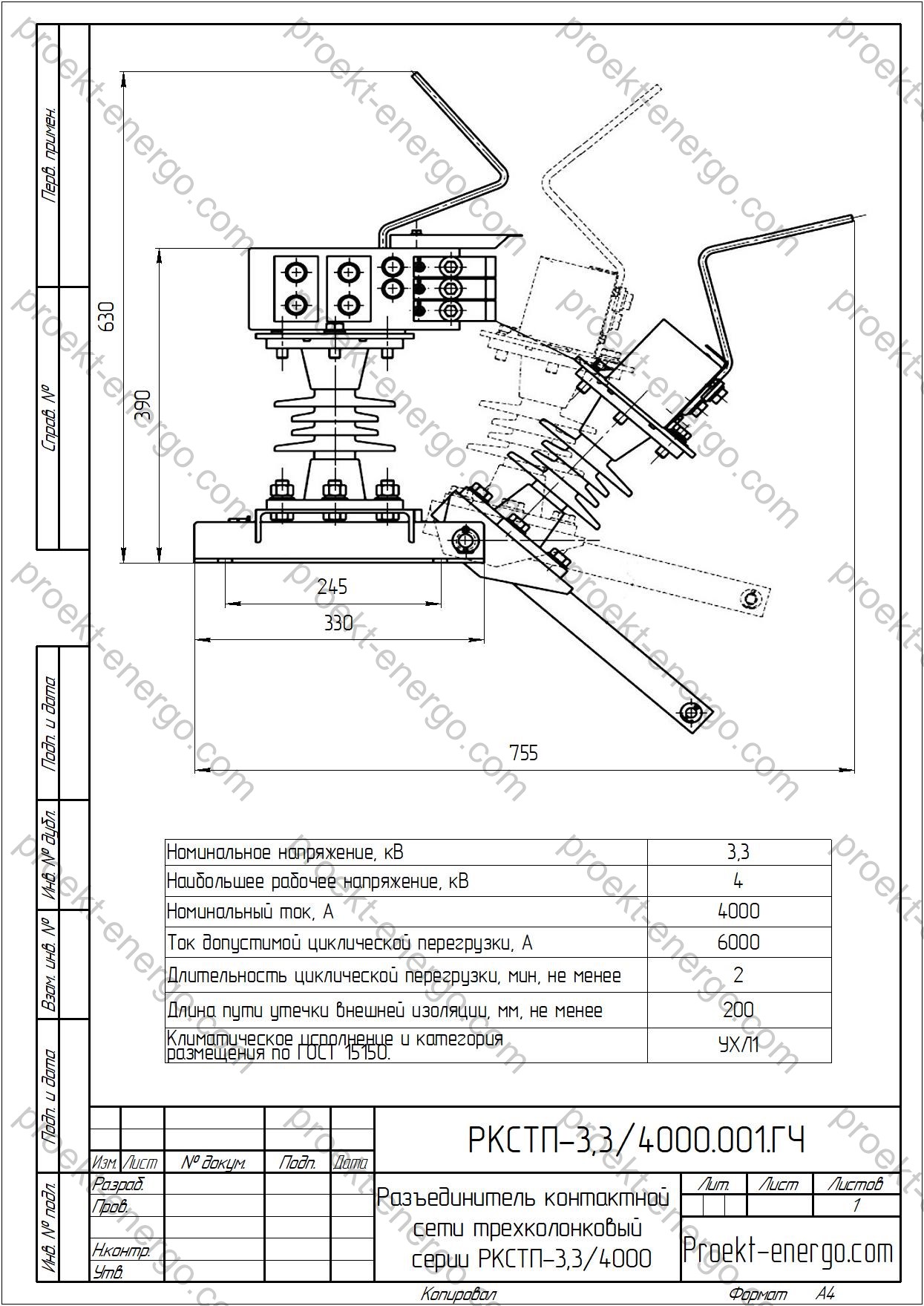
Technical Data

Rated voltage, kV 10
Maximum system voltage, kV 12
Rated current, A 400; 630
Short-time (thermal) withstand current, 3 s, kA 20
Dynamic (peak) withstand current, 1 s, kA 51
Mechanical endurance of main circuit, O-C cycles 2000
Climatic design and location category (GOST 15150)  U2

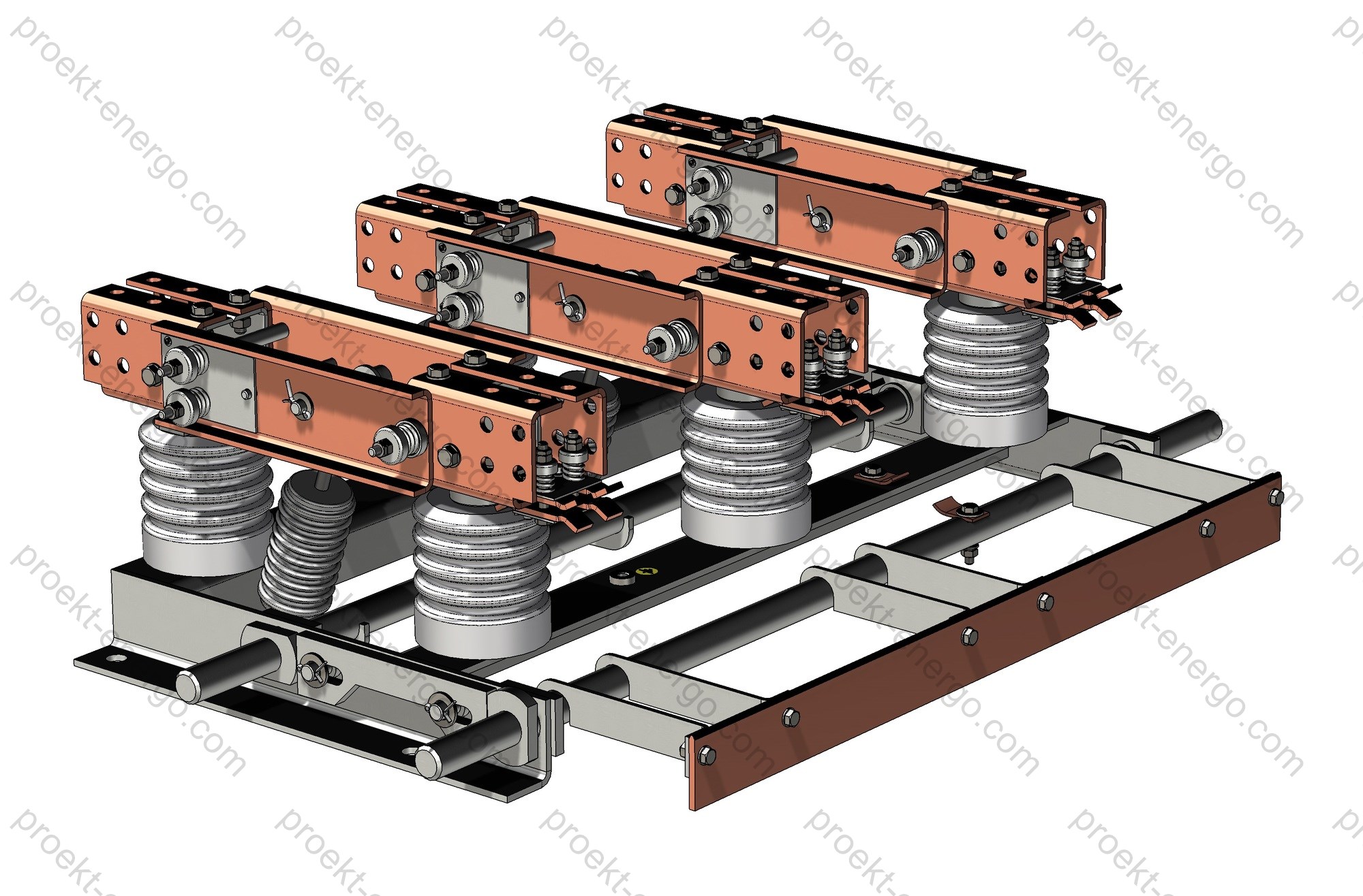
Design and Construction

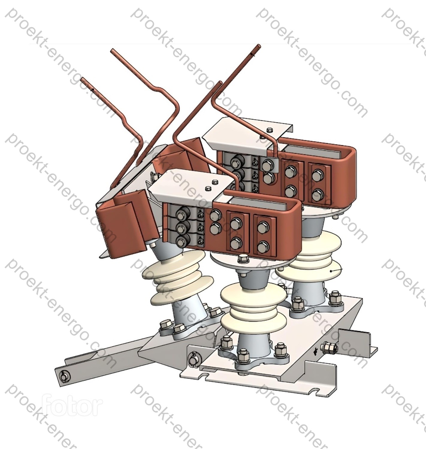
The VNA-10 is a three-pole device with a visible isolating gap and a self-generated gas (auto-expansion) arc-quenching system. Main assemblies include: welded base frame (plinth), bushing insulators, fixed and moving main-circuit contacts, bridging current-carrying blades, arc-quenching chambers made of gas-generating polymer material, mounting and adjustment hardware, interlocking mechanism, and provisions for earthing blades with reliable kinematic linkage to the operating mechanism. Contact surfaces are copper-alloy with a hardened coating to ensure low contact resistance and high erosion resistance under repeated operations.

The auto-expansion arc-quenching principle uses gases released from the arc-chute walls as the arc develops. The generated gas displaces and cools the plasma, promotes de-ionization of the contact gap and rapid recovery of dielectric strength. This enables reliable interruption of load currents and limited switching currents without complex extinguishing media. Chamber geometry and contact profiles are optimized to direct the gas flow, reduce wear and minimize pressure in the arc zone.

The switch is equipped with separately mounted operating mechanisms - manual spring-charged (PR-10/PRBD-10) or motor operators for remote control. Left-hand (VNA-L) and right-hand (VNA-P) drive arrangements are available, simplifying alignment with existing bay doors, cable entries and neighboring equipment. The mechanism stores energy prior to operation and releases it rapidly at the switching instant, reducing arcing time and thermal stress on the contacts. For integration into protection/automation and SCADA/DCS, limit micro-switches provide “dry-contact” position signals “ON/OFF/EARTHED”.

For ease of service, the design provides access to the arc-chutes and contact system from the front of the bay with minimal disassembly. Adjustment points have baseline marks; allowable tolerances and tightening torques are specified in the O&M documentation. Connection dimensions and busbar profiles match widely used KSO/KRU solutions; adapter kits are available to interface with non-standard connection planes and phase spacing. For combined use with medium-voltage fuses (PKT/PKN), cable entries and holders are provided within transformer-protection bay designs.

Safety and Interlocks

Personnel safety is ensured by several protection layers. Mechanical interlocks prevent closing of the main circuit with the earthing switch engaged and prevent selection of the “EARTHED” position when the main circuit is closed. Electromechanical locks and door interlocks inhibit cabinet opening when voltage is present or when the device is not latched in a defined position. Provisions are made for padlocks and warning tags during permit-to-work activities. A visible isolating gap and clear position indication on the mechanism panel improve the reliability of state identification.

The supply package and operating documentation specify interlock checks, maintenance intervals and personnel requirements. Position signalling and integration into SCADA/DCS enable remote supervision, preventing erroneous actions during operations. The mechanical strength of insulators, busbars and fasteners is verified during routine and acceptance tests, assuring compliance with electrical and mechanical safety requirements throughout the device life cycle.

Options and Accessories

Option Description Purpose
Position signalling contacts “Dry contacts” ON/OFF/EARTHED Integration with protection/SCADA
Viewing windows Transparent inserts in bay doors Visible isolating gap
Motor operator Remote control Operations without entering the switchgear room
Fuse set PKT/PKN to project rating Transformer protection
Bus adapter kit Transition plates, busbars Modernization of existing KSO

Standards Compliance

  • IEC 62271-103 - medium-voltage load break switches: general requirements and test methods.
  • IEC 62271-102 - disconnectors and earthing switches (requirements for earthing assemblies).
  • IEC 62271-1 - common specifications for medium-voltage switchgear and controlgear.
  • IEC 62271-200 - AC metal-enclosed switchgear and controlgear (1–52 kV); requirements for cubicles housing load break switches.
  • EN/IEC 60721-3-3 - environmental conditions for stationary use at weather-protected locations (climatic category for indoor installation).

Engaging Contractors and Partners

We invite switchgear manufacturers, electrical EPCs and installers, SCADA/DCS integrators, service companies and investors interested in localizing production of VNA-10 load break switches. We provide a full cooperation cycle: review of the specification, adaptation of design documentation to your machinery park, selection of materials and components, development of routing sheets and quality-control instructions, personnel training and support for serial production launch. On request we arrange fabrication of assemblies at partner facilities (machining, plating, plastics, stamping) with incoming/in-process control, and perform acceptance tests per the project’s program and procedures.

Documentation Offered

We supply a complete documentation set to manufacture VNA-10/400 and VNA-10/630 at your facility: BOMs, assembly drawings, 3D models, parts lists, lubrication and adjustment charts, electrical and kinematic schematics, installation and interlock-adjustment instructions. Available formats: DWG/DXF (AutoCAD), SLDPRT/SLDASM (SolidWorks), Parasolid (x_t/x_b), STEP, PDF. If required, we will adapt to specific KSO/KRU layouts, verify mechanical interfaces, calculate busbar current loads, and recommend contact pressures and tightening torques. If you do not plan to manufacture certain parts in-house, we will place them with vetted suppliers; your site will handle assembly, adjustment, testing and packing.

Service Life and Maintenance

Mechanical life to first major overhaul - at least 2000 O-C cycles; interval between overhauls - at least 1000 operations. Follow the prescribed maintenance per the O&M manual: visual inspection of assemblies, condition check of arc-chutes, verification of deposition on contact surfaces, insulation cleaning, lubrication of sliding pairs, interlock inspection/adjustment, torque checks of fasteners, and verification of limit switches. To ensure stable performance, observe the tightening torques and contact pressures specified in the technical documentation.

Advantages of Working with Us:

- No need to maintain a large engineering staff: you receive a standardized documentation package suitable for an engineer of average qualification.
- Launch of serial production without a prolonged prototype stage: we use proven solutions and standard units with industrial track record.
- Consulting support at all stages: from procurement of materials and components to commissioning, staff training and acceptance testing with formal protocols.

For additional information on VNA-10 load break switches: inbox@proekt-energo.com

…as is well known, an error made in design leads to tenfold costs in manufacturing and a hundredfold in operation. High-quality documentation and competent cooperation are the key to reliable performance of 6–10 kV distribution networks.

PDF - Download technical information on VNA-10 load break switches.

pdf

Disconnector GN38-12

GN38-12 Changeover Disconnector

The indoor AC GN38-12 changeover disconnectors are intended to make and break, without load, individual sections of a medium-voltage network up to 12 kV (50 Hz), and to provide safe earthing of the disconnected sections. The GN38-12 series are three-pole, vertical-break (changeover) devices with a compact layout, designed for installation in KRU/KSO panels and distribution switchgear cabinets where footprint, reliability and ease of maintenance are critical.

Purpose and application

The GN38-12 disconnector is used to create a visible break for operational switching, maintenance and repair on 6–12 kV distribution assets: on incoming feeders and sections of KRU/KSO, in busbar chambers, in feeder bays (cable, line, transformer), as part of main and distribution substations. The device provides:

  • operational isolation of the de-energized section (visible break);
  • workzone delimitation by earthing the circuit via the built-in earthing switch (if so equipped);
  • sectionalizing and maintenance switching without load;
  • interlocks to prevent personnel errors via mechanical and key-type interlocks.

The compact design allows GN38-12 to be used in small KSO-type cubicles, modular switchgear, shallow cabinets and retrofit bays without re-engineering the entire panel. Thanks to the three-position logic (ON – OFF – EARTHED), the device integrates easily into typical distribution schemes, and the availability of different operating mechanisms gives flexibility in design.

Technical data

Rated voltage, kV 10
Maximum system voltage, kV 12
Rated current, A 400; 630; 1000; 1250
Short-time withstand current (3 s), kA 16; 20; 25; 31.5
Peak (dynamic) withstand current (1 s), kA 40; 50; 63; 80
Mechanical endurance of main circuit, O-C cycles 2000
Environmental category (indoor), per EN/IEC 60721-3-3 (equiv. to GOST 15150 U2) U2

Service conditions

GN38-12 disconnectors are intended for indoor installations under the following (typical medium-voltage) conditions:

  • Location category: indoor installation (MV switchgear rooms, KRU/KSO, cabinets);
  • Ambient temperature: -25 °C to +40 °C (short-term excursions per project), without condensation during operation;
  • Altitude: up to 2000 m (above this, recalc of insulation clearances and test levels is required);
  • Relative humidity: up to 95% (daily) with no condensation;
  • Atmosphere: free from corrosive vapours/gases in concentrations harmful to insulation and metals; no conductive dust or aerosols;
  • Vibration and shocks: not exceeding the levels specified for MV switchgear mechanical robustness (per IEC/GOST);
  • Environmental category: U2 (per legacy GOST classification).

When designing the switchgear, consider ventilation modes (natural/forced), possible local hot spots inside the cabinet, minimum creepage distances and clearances between live parts, and the impact of heating/dehumidification on dielectric strength.

Design and construction

The GN38-12 is a three-pole unit on a welded base frame including the following major assemblies:

  • Bushing insulators (upper/lower) – provide mechanical strength and dielectric insulation of live parts from the frame and cabinet;
  • Changeover current-carrying blade (vertical-break type) – forms a visible break and makes connection to the earthing contact in the “EARTHED” position;
  • Contact system – fixed and moving contacts with enhanced wear resistance; spring elements maintain contact force;
  • Earthing switch (option) – located on the fixed or moving contact side, mechanically interlocked with the main blade;
  • Linkage system – transmits force from the mechanism to all three poles, ensuring synchronism and positive position latching;
  • Three-position operating mechanism (e.g., type ZQL or equivalent) – provides “ON”, “OFF”, “EARTHED” positions; supports sealing and limit switches.

Current-carrying parts are selected for low contact resistance and long-term stability (electro-technical copper/copper alloys with galvanic coating). Insulators and insulating panels are sized with adequate creepage and withstand levels for indoor service and the site’s pollution degree. The design requires minimal upkeep: periodic visual checks, tightening of bolted joints, insulation cleaning and mechanism inspection.

AssemblyFunctionKey features
Base frame Mounting base for all poles and mechanism Welded construction; high rigidity; slotted holes for adjustment
Bushing insulators Dielectric insulation and mechanical support Porcelain or epoxy; increased creepage distance
Changeover blade Visible break and earthing Vertical-break type; spring-assisted contact pressure; withstands dynamic forces
Contact system Reliable current contact in “ON”/“EARTHED” Reinforced jaws; wear-resistant coatings; low contact resistance
Three-position mechanism Selecting “ON/OFF/EARTHED”, position indication Provision for interlocks, limit switches, sealing

GN38-12 disconnectors are manufactured with or without a built-in earthing switch. The main blades and the earthing blade are driven by a single three-position mechanism with fixed positions: “disconnector closed”, “disconnector and earthing switch open”, “earthing switch closed”. The mechanism incorporates interlocks that prevent an incorrect sequence of operations. Interlocking with the circuit breaker of the respective bay is provided.

Mechanical endurance before first major overhaul is at least 2000 operations. The interval to a medium overhaul is at least 1000 cycles with a service period up to 4 years. Nominal service life - 25 years, subject to the maintenance schedule and service conditions.

Safety and interlocks

Personnel safety is ensured by a combination of design and procedural measures:

  • Three-position logic: prevents simultaneous energization of live parts and closing of the earthing blade;
  • Mechanical interlocks of the mechanism: blocking “ON” when the earthing switch is engaged, and vice versa;
  • Key and mechanical interlocking with the circuit breaker and bay doors (keylocks, position limit switches);
  • Visible break for visual confirmation of the de-energized state before work;
  • Sealing of the operating handle to fix operational status;
  • Provision for portable earthing points to support safe work procedures.

When engineering interlocks, consider the switching sequence, access to the handle, the blade travel envelope, and the requirements of electrical safety rules for locking, labelling of controls and position indication.

Variants and options

The GN38-12 is supplied in various construction and equipment options to fit a specific switchgear, bay dimensions and customer requirements:

  • with a built-in earthing switch or without it (on the fixed or moving contact side);
  • left- or right-hand mechanism location; different blade orientations;
  • connection options: for busbar packs, cable lugs, flexible connections;
  • insulator versions: porcelain/epoxy (indoor), increased creepage distances;
  • installation of limit switches (dry contacts) for position telesignals;
  • optional motor-operator (per project) for remote control;
  • anti-skew provisions through adjustable links and position latches.
OptionDescriptionPurpose/remark
Built-in earthing switch Earthing blade mechanically interlocked with the main blade Operational earthing of the isolated section
Limit switches Dry contacts for “ON/OFF/EARTHED” telesignals Integration with SCADA/P&C
Motor-operator Three-position electric actuator Remote control/automation
Interlock kit Key/mechanical interlocks Prevention of incorrect operations
Connection variants For busbars, cable lugs, flexible bars Project unification

Standards compliance

Design and manufacture of the GN38-12 follow applicable standards for medium-voltage apparatus:

  • IEC 62271-102 / EN IEC 62271-102 - AC disconnectors and earthing switches (requirements, type tests);
  • IEC 62271-1 - Medium-voltage switchgear and controlgear - Common specifications;
  • EN/IEC 60721-3-3 - Environmental conditions for indoor locations (replaces legacy GOST 15150 categories for indoor use);
  • General mechanical robustness - according to enterprise specifications and applicable IEC guidance;
  • Electrical installation rules - applied as relevant to 6–35 kV MV switchgear;
  • Enterprise standards (drawings/specs) - interface dimensions, interlocks, TS/remote control interfaces.

Engaging contractors and partners

We welcome cooperation with electrical equipment manufacturers, KRU/KSO switchgear integrators, design and installation firms, as well as investors interested in localizing/organizing production of the GN38-12 series. We offer:

  • transfer of design document packages (from preliminary documentation to a full set for serial production);
  • adaptation of design solutions to your site’s manufacturing capabilities (tooling, machine park, plating, painting);
  • selection and qualification of the supply chain (insulators, stamping/machining, subassembly);
  • advice on type/routine tests, FAT/SAT methodologies, and preparation of programs and reports;
  • support for initial series, staff training, commissioning support.

Documentation offered

Available preliminary technical documentation for tenders (questionnaires, specifications, explanatory notes) and a full set of manufacturing documentation for production at your site:

  • assembly and detail drawings (DWG/DXF, BoMs, parts lists);
  • 3D models of parts and assemblies (STEP/IGES/Parasolid (x_t), SolidWorks, Inventor);
  • electrical diagrams, interlocking maps, TS/remote control wiring, cable schedules;
  • work instructions for assembly/adjustment, inspection routes, test programs;
  • typical O&M documentation (datasheet, manual, test records).

On request, documents can be tailored to the project requirements and manufacturing capabilities (busbar thicknesses, interface dimensions, mechanism type, limit switch and cable gland locations, insulator type, etc.).

Why work with us

- No need for a large in-house engineering team: you receive a ready-to-build documentation set.
- No “pilot dead-ends”: our experience enables starting from series with minimal tweaks.
- Expert advice on all nuances of manufacturing and testing the GN38-12, assistance with tooling and quality control programs.

For additional information on GN38-12 disconnectors: inbox@proekt-energo.com

...as is well known, an error made at the design stage costs ten times more in manufacturing and a hundred times more in operation - it is best to allow for everything in advance.

PDF - Download technical information for the GN38-12 disconnector.

pdf

Disconnector RV-10/2000; RVZ-10/2000

RV-10/2000; RVZ-10/2000 Indoor Disconnector for currents up to 2000 A

The indoor disconnectors RV-10/2000; RVZ-10/2000 are intended for isolating de-energized sections of an electric circuit that are live, as well as for grounding the isolated sections by means of built-in earthing switches. Rated current - up to 2000 A.
Structurally, these are vertical-break type disconnectors manufactured in a three-pole design. 
RV disconnectors are supplied without an earthing switch; RVZ - with an earthing switch on either the separable-contact side or the non-separable side.
The RV/RVZ disconnectors consist of a base frame, support insulators, contact system, pull-rod (operating) insulator and earthing switches. A drive shaft with levers mounted on the frame operates the contact blades. If earthing switches are provided, one or two additional shafts are installed to operate them together with a mechanical interlock that prevents closing the earthing switch with the main blades closed, and vice versa. Insulation comprises support insulators and the pull-rod insulator. The contact system includes copper fixed contacts and moving contact blades. The earthing switch is a copper bar fixed to steel posts welded to the earthing shaft. When operated, the bar engages multi-finger contact blocks mounted on the lower shelves of the fixed contacts. Contact pressure in the axial and separable (blade) contacts of the main blades and in the finger contacts of the earthing switch is provided by springs.
RV/RVZ disconnectors are designed for environmental classification per EN/IEC 60721-3-3 with the following limits:
- altitude not exceeding 1000 m above sea level;
- upper working ambient temperature +40 °C;
- lower working ambient temperature -45 °C;
- relative humidity 80% at +20 °C.

Technical data

Rated voltage, kV 10
Maximum system voltage, kV 12
Rated current, A 2000
Rated short-time withstand current (3 s), kA 31.5
Rated peak withstand current, kA 80
Mechanical endurance of main circuit, O–C operations 2000
Environmental classification (replacement for GOST 15150 U3) EN/IEC 60721-3-3

Purpose and applications

The RV-10/2000 and RVZ-10/2000 disconnectors are part of indoor medium-voltage distribution equipment for 10 kV systems and are intended for safe operational isolation of circuit sections, busbar sections and KRU/KRUN cubicle feeders, as well as for a visibly verifiable break during maintenance and commissioning. The devices are not intended to interrupt load or short-circuit currents and are operated together with circuit-breakers and fuses that perform load and short-circuit switching. The built-in earthing blades (RVZ versions) enable fast and reliable grounding of the isolated section, reducing job-site preparation time and improving electrical safety.

Typical applications: distribution points and substations, main step-down substations, factory and commercial KRU switchgear, sectioning and incomer cubicles, auxiliary service transformer feeders, ATS/ABT bus sectioning, temporary maintenance jumpers. The disconnectors are effective in schemes with high rated currents (up to 2000 A) and elevated requirements for mechanism reliability and a clearly visible isolation gap.

Service conditions

Designed for indoor installations without aggressive gases or conductive dust, under standardized microclimate parameters. Permissible installation altitude - up to 1000 m; for higher sites, increased insulation clearances and reassessment of withstand levels can be provided by agreement. Operating temperature range: -45 °C to +40 °C; relative humidity - up to 80% at +20 °C. Operation under increased vibration and industrial shock is allowed provided the mounting and alignment requirements of the drive mechanism are met. The units withstand short-time thermal stresses (3 s) and electrodynamic forces under short-circuit currents (see technical data above). For dusty rooms, periodic inspection and scheduled cleaning of insulation and contact assemblies are recommended.

Design and construction

Vertical-break (rotating blade) scheme with three support insulators per pole and a common drive for three phases. This kinematic arrangement ensures compactness within cubicle dimensions, minimal interphase distances, low mechanical losses and stable contact force throughout closing travel. Support insulators - porcelain or polymer with increased bending strength; the pull-rod insulator is designed to transmit axial loads from the operating shaft.

The current-carrying system uses copper bars and blades with brazed or welded contact overlays. Fixed contacts employ multi-finger spring contact blocks, providing low contact resistance and self-cleaning of working surfaces during cycling. Contact pressure in axial and separable (blade) joints is provided by spring packs, maintaining stability over the entire temperature range. Blade rotation nodes use bushing-roller bearings with a low friction coefficient; friction points are protected from dust and accessible for inspection.

The welded base frame features high rigidity, reference holes for mounting to the KRU panel/foundation, and adjustment slots for precise pole alignment. The operating shaft exits to the cubicle front for manual or motor-operated drives. For RVZ versions, additional shafts actuate the earthing blades with independent kinematics. Standard supply includes mechanical end-stops, latching of end positions, and an external position indicator “ON/OFF/EARTHED”.

Electrical insulation meets the requirements of 10–12 kV distribution equipment; necessary clearance and creepage distances are provided, with insulator materials and shed profiles selected for indoor installations and the room’s pollution class. Provision is made for holes and pads for bus links, flexible connectors, take-offs to current/voltage transformers and test blocks. Versions with left- or right-hand drive-shaft placement, as well as mirror arrangements for symmetric panels, are available.

Safety and interlocks

Standard mechanical interlocks exclude closing the earthing blades with the main blades closed and prevent simultaneous “ON” and “EARTHED” positions. A latch prevents position change due to vibration. Provisions are made for padlocks and for microswitches (NO/NC auxiliary contacts) to implement electrical interlocks with adjacent equipment (circuit-breakers, transformers, drive cabinets). Clear visual position indicators are brought to the front; direction of rotation and operating angles are standardized for drive unification. The design ensures safe visual confirmation of the visible isolation gap and reliable grounding of the isolated section in accordance with occupational safety and operating rules for electrical installations.

Versions and options

Base versions: RV-10/2000 (without earthing blade) and RVZ-10/2000 (with built-in earthing blade on either the separable or non-separable contact side). Available on request: AC/DC motor-operator; increased mechanical endurance; polymer insulators; additional position auxiliary contacts; silver-plated contact surfaces; reversible drive-shaft arrangement; dimensional variants tailored to specific KRU/KRUN cubicles; bus connection kits; shielding covers for live parts; quick-install kits and alignment templates.

Option Description Purpose / effect
Motor-operator Electrical control with remote position indication Automation, remote operation, reduced human factor
Auxiliary contacts 2–8 changeover contacts for “ON/OFF/EARTHED” Interlocking schemes, telesignaling, SCADA/DCS
Polymer insulators High-resilience silicone composites Weight reduction, pollution resistance, easier service
Silvered contacts Thin Ag layer on working surfaces Minimal contact resistance, improved corrosion resistance
Mirror arrangement Left/right drive-shaft, reversed kinematics Convenient layout in different KRU cubicles

Standards compliance

Design and manufacture follow applicable international and regional standards for medium-voltage switchgear and disconnectors:

  • IEC 62271-102 / EN 62271-102 - AC disconnectors and earthing switches (latest edition with amendments).
  • IEC 62271-1 - General requirements for medium-voltage switchgear and controlgear.
  • IEC 60529 - Degrees of protection (IP Code) for enclosed parts.
  • EN/IEC 60721-3-3 - Environmental conditions - Classification of groups of environmental parameters and their severities (indoor, weather-protected locations).

Materials and finishes

Current-carrying parts are made of electrolytic copper with optional tin or silver plating of contact surfaces. Steel frame elements have powder-coat or zinc-rich primer finishes suitable for industrial indoor environments. Stainless fasteners are used in critical assemblies; plastic parts are made of flame-retardant materials meeting the fire-safety requirements of distribution equipment.

Assembly Material / finish Service notes
Blade and bars Copper (Cu-ETP), tin- or silver-plated contact pads Low contact resistance, oxidation resistance
Fixed contact Multi-finger spring contact blocks Self-cleaning and uniform force over many cycles
Insulators Porcelain / polymer (silicone) High mechanical strength, contamination resistance
Frame Steel with powder coating Corrosion protection, geometric stability
Bearing units Steel/bronze, lubricated per schedule Durability, smooth mechanism travel

Contractors and partners

We invite cooperation with electrical equipment manufacturers, mechanical assembly plants, I&C service companies, investors and engineering organizations. We provide a complete set of design and technological documentation, bills of materials and purchase lists, as well as support during production preparation, assembly, commissioning and product acceptance. We are open to joint supplies of components (insulators, finger contacts, drives), localization and cooperation.

Available documentation (drawings, 3D models)

Package contents: outline and mounting drawings, assemblies, manufacturing drawings for units and parts, external connection diagrams, 3D models (STEP/Parasolid), drawings in DWG/DXF (AutoCAD) and SLDDRW/SLDASM (SolidWorks), parts lists and specifications, installation and maintenance instructions, lubrication charts, inspection check sheets. On request we prepare adaptation to your technology: routing sheets, work instructions, tooling and alignment templates, incoming inspection programs for supplied components.

Why work with us

- No need to maintain highly qualified design staff - you receive a documentation set for the product that can be used by a mid-level engineer. 
- No need to build prototypes - our experience enables direct launch of serial production batches.
- Working to our documentation, your specialists receive consultation on all aspects of manufacturing RV-10 disconnectors.

For additional information on RV-10/2000; RVZ-10/2000 disconnectors, please contact: inbox@proekt-energo.com

…as is well known, an error made during design turns into 10× the cost in manufacturing and 100× during operation…

PDF - Download technical information for RV-10/2000; RVZ-10/2000 disconnectors

pdf

Disconnector RKSTP-3,3/4000

RKSTP-3.3/4000 Three-post 3.3 kV overhead contact line disconnector with polymer insulation

The RKSTP-3.3/4000 three-post disconnector with polymer insulation, 3.3 kV, is designed for making and breaking, with no load, live but unloaded sections of the DC overhead contact line of electrified railways. When operated by a motor drive it can also interrupt, at the highest service voltage, currents of auxiliary machines of rolling stock, coach heating currents, and-under emergency conditions-back-feed currents of adjacent substations.
The RKSTP-3.3/4000 is manufactured for outdoor installation (placement category 1) in temperate/cold climates. Environmental categories are specified in EN/IEC 60721-3-4; operability is ensured under the following conditions:
- altitude up to 1000 m above sea level;
- upper working ambient temperature +40 °C;
- lower working ambient temperature -60 °C;
- no ice accretion with maximum wind pressure 1000 Pa (equivalent wind speed 40 m/s);
- with ice accretion up to 20 mm and wind pressure 140 Pa (equivalent wind speed 15 m/s).
The RKSTP-3.3/4000 provides mechanical robustness suited for outdoor OCL structures; vibration resistance corresponds to heavy-duty service for pole-mounted equipment.
Regarding thermal performance, the disconnector allows the following duty in terms of temperature rise:
- continuous current 4000 A with connection to eight copper conductors type M120 or eight aluminium conductors type A185 per GOST 839-80;
- cyclic overload duty with the same connections:
2 min – 6000 A
4 min – 5000 A
Operation is normally by a motor drive unit type PDM-G (UHL1). Interfacing to other drive types with technical parameters equivalent to PDM-G is permitted.

Technical data

Rated voltage, kV 3.3
Maximum service voltage, kV 4
Rated current, A 4000
Permissible cyclic overload current, A 6000
Cyclic overload duration, min, not less than 2
Maximum current interruptible by the disconnector, A, not less than
at network inductance 300 mH
at network inductance 35 mH


10
500

External insulation creepage distance, mm, not less than 200
Minimum open-gap between contacts in the OFF position, mm, not less than 120
Mass, kg, not more than 60

Purpose and application

RKSTP-3.3/4000 is used in 3 kV DC traction power systems for operational sectioning of the overhead contact line (OCL) on open line, stations, traction substations and sectioning posts. The device provides a visible break and ensures safe creation of working zones when servicing pantograph and contact wires, catenary/messenger, return feeders, jumpers and take-offs. The three-post arrangement provides simultaneous action on all live parts of the section, which is important for by-pass schemes, backup switching and clearing faulted conditions.
With a motor drive the unit can be integrated into remote control and telemechanics/SCADA (DPR, ASDU) for fast restoration of normal supply, isolation of faulty sections and execution of switching programs without sending crews trackside. In manual mode the unit ensures reliable operation within local control schemes on OCL structures and in traction substation distribution yards. RKSTP is effective for:
- sectioning inter-substation and inter-feeder spans;
- creating neutral sections where high return currents occur;
- isolating areas for scheduled or emergency works;
- fast reconfiguration of yards, sidings and depot power schemes;
- establishing jumpers and by-passes in case of OCL damage or adjacent device outage.

Service conditions

The disconnector is intended for outdoor installation (placement category 1), including regions with temperate and cold climates. The design withstands long-term exposure to UV, precipitation, icing, wind loads and flying ice/snow typical for OCL structures and open-air distribution gear. Polymer post insulators are made of UV-, tracking- and weather-resistant material with a hydrophobic surface that promotes self-cleaning and maintains creepage distance in pollution. Operation is permitted in dusty areas, marine aerosol and railway de-icers provided the inspection/cleaning regimen is observed.
The unit resists vibration and shock from rolling stock and wind-induced mast sway, and temperature cycles from -60 °C to +40 °C. Base and fasteners have anti-corrosion protection; installation is possible on steel or reinforced-concrete poles, gantries and substation structures. A reliable earthing point is provided on the base, and a weather shield protects the open-gap zone from direct precipitation.

Design and construction

RKSTP-3.3/4000 is a vertical-break, three-post, polymer-insulated medium-voltage disconnector. Two fixed contact units and a moving blade form a visible break in the open position. To ensure dependable interruption of auxiliary-circuit currents, arcing contacts with defined make/break sequence relative to the main contact are used, reducing lamella erosion and extending life. The drive (motor or manual) transmits force via a linkage to the blade lever; fine adjustment of contact pressure, overlaps and clearances is provided. The contact zone is shielded from rain/snow, and current-carrying parts are shaped to reduce electrodynamic forces during impulse currents.
Contact surfaces are made of conductive alloys with wear-resistant coatings; spring elements maintain stable lamella pressure over temperature cycles and vibration. Overall dimensions and minimum open-gap provide the required dielectric strength. The design includes:
- earthing bolt on the base;
- terminals for multi-strand flexible conductors (Cu/Al) as per project specification;
- mounting points for limit switches/position sensors;
- adjustable stops ensuring repeatable end positions;
- convenient access for maintenance without removing the unit.

Assembly / part Material / design Function / features
Post insulators Polymer, UV- and tracking-resistant Stable creepage distance, low mass
Main contact Lamellar system with spring pressure Low contact resistance, high operating life
Arcing contacts Copper contact elements Leading/trailing sequence reduces erosion
Base and brackets Steel with anti-corrosion coating Rigidity and weather resistance
Weather shield Metal/polymer, weatherproof Protects open-gap from precipitation/icing
Linkage Adjustable rods and levers Precise setting of overlaps and clearances

Safety and interlocking

The design provides a visible isolation gap, provisions for padlocks and mechanical interlocks in end positions, and dry-contact limit switches for remote “ON/OFF” indication. Points for sealing and handle/shaft locking are provided. Installation and operation shall follow applicable rules for operation of electrical installations. To prevent mal-operation, the disconnector can be equipped with kinematic interlocks with the drive and adjacent apparatus as per project. The base has a standard earthing bolt; terminals and live parts can be guarded/shielded to reduce accidental contact risk.

Variants and options

The disconnector can be supplied:
- with a motor drive (e.g., PDM-G UHL1) for remote control and SCADA integration;
- with a manual drive (e.g., PRZh-UHL1) for local pole-mounted control;
- with a set of limit switches / microswitches for telesignalling;
- with additional rain/snow shields, customized brackets for specific structures, and installation kits;
- with terminals for copper/aluminium flexible bars per project;
- with site-specific identification (tags, nameplates, labels).

Drive type Designation (example) Purpose Interfaces / functions
Motor PDM-G UHL1 / PDZh-1 UHL1 Remote operation, automation Dry-contact position signals, telemechanics-ready
Manual PRZh-UHL1 Local control on structure Position latching, provision for interlocks
Equivalent By agreement Compatible with equivalent drives Compatibility confirmed during commissioning

Compliance with standards

The equipment and its use in overhead contact line systems comply with relevant international and European standards, including:
- EN/IEC 60721-3-4 - environmental conditions for stationary use at non-weather-protected locations (climate category for outdoor installation);
- EN 50119:2020 - Railway applications, fixed installations, electric traction overhead contact lines;
- EN/IEC 61992 (series) - Railway applications, fixed installations, DC switchgear (incl. outdoor d.c. disconnectors/switch-disconnectors/earthing switches);
- EN 50110-1 - Operation of electrical installations (safety of work procedures).
Where applicable, mechanical and environmental testing follows IEC 60068 methods.

Engagement with contractors, manufacturers and investors

We welcome co-operation with mechanical plants, electrical apparatus manufacturers, engineering firms and investors interested in launching the RKSTP-3.3/4000 and related OCL products. Possible co-operation models:
- licensing of design documentation with author support;
- supply of components and semi-finished parts with partner-side localization;
- split manufacturing by assemblies (mechanics, insulation, drives) with final assembly by the partner;
- turnkey tender participation with engineering support, supervision and staff training;
- product adaptation to requirements of national railways and local codes, including existing drive types, structures, brackets and telemechanics.

Documentation offered (drawings, 3D models, AutoCAD, SolidWorks, DXF, DWG, Parasolid)

On request we provide a complete design package for manufacturing and deployment of RKSTP-3.3/4000 disconnectors:
- preliminary documents for tenders and techno-commercial proposals (data sheets, diagrams, specifications, 3D views);
- working drawings, 3D models (Parasolid/STEP), DWG/DXF packages, CAM models, bills of materials;
- installation, adjustment, commissioning and operation manuals; test programs and procedures;
- passports, forms, quality control tables, lubrication charts and maintenance schedules;
- if required, adaptation of documents to your production capabilities and typical drives (including interlocking and signalling schemes).

Benefits of working with us

- No need to retain a large high-grade engineering staff - you receive a complete documentation set allowing manufacture by a mid-level engineer.
- No need to build costly prototypes - our experience allows direct launch of serial batches.
- Working to our documentation, your team will receive detailed guidance on all nuances of manufacturing RKSTP-3.3/4000 disconnectors.

For more information on RKSTP-3.3/4000 disconnectors contact: inbox@proekt-energo.com

…and, as is known, an error made at the design stage costs 10× at manufacturing and 100× in operation.

PDF - Download technical information for RKSTP-3.3/4000 disconnectors

pdf

RNDZ-27.5 Sectioning disconnector

RNDZ-27.5 Sectioning disconnector for 27.5 kV overhead contact system

The RNDZ-27.5 series sectioning disconnectors are intended for operational switching of previously de-energized 27.5 kV AC sections and for their subsequent safe earthing by integrated earthing switches. The design provides a clearly visible isolating gap. Units are supplied in single-, double- and triple-pole versions; the pole coupled to the operating mechanism is the leading pole. Operation is via manual or motor drives; provision is made for fitting limit switches and auxiliary contacts for remote control and telemetry.
Environmental and service conditions - in accordance with EN 50125-2 (fixed installations). Permissible operating parameters:
- installation altitude ≤ 1000 m a.s.l.;
- ambient temperature -60 to +40 °C;
- wind speed up to 40 m/s without icing and up to 15 m/s with ice up to 10 mm thick;
- average annual relative humidity 80% at +15 °C;
- max. wind pressure 700 Pa (≈34 m/s) without icing;
- max. wind pressure 140 Pa (≈15 m/s) with ice sheath up to 10 mm;
- total permissible mechanical load on one pole’s terminals (including wind/ice loads) - 500 N with uniform distribution.
Insulation performance meets the requirements of the 27 kV voltage level per EN 62271-1; test methods per IEC 60060-1. External creepage distance of porcelain insulators on standard versions:
- pollution level I - not less than 60 cm;
- pollution level II - not less than 105 cm.
On request - execution with polymer insulators type ОСК8–35–Б–2 with creepage ≥ 105 cm. Mechanical endurance - at least 2000 “close-open” cycles.
The disconnectors are not intended for operation under pronounced vibration, impacts or other dynamic effects exceeding industry norms.

Technical data

Rated voltage, kV 27.5
Highest voltage for equipment (Um), kV 30
Rated current, A 1000; 1600
Rated peak withstand current, kA 63
Rated short-time withstand current, kA 25
Short-time duration, s
- main blades
- earthing blades

3
1
Frequency, Hz 50
Creepage distance of external insulation, cm ≥ 60
Allowable horizontal conductor tension, N ≤ 800
Environment / installation category per EN 50125-2 / outdoor
Mass (typical), kg 1 pole ~53/62; 2 poles ~118
Overall dimensions (typical), mm height 960 / 1300; width 750 / 840 / 930

Application and use

AC overhead contact system sectioning disconnectors of the RNDZ type are high-voltage devices for performing operational switching with no load current. Their primary task is to connect/disconnect previously de-energized sections of the OCS while ensuring electrical safety during maintenance, installation and inspection. In the open position the device provides a visible isolating distance that confirms physical separation of the work section from the power supply - a requirement of EN 50122-1 and operating rules.

As an option, fixed earthing switches are installed to reliably earth isolated sections and eliminate hazards due to induced voltages or inadvertent energization. The term “sectioning” reflects the function - dividing the OCS into electrically separated zones for flexible operation and fault containment.

Design and operating principle

General arrangement

RNDZ units are two-column, horizontally rotating disconnectors for outdoor installation. This kinematics is well suited for railway infrastructure: the rotary motion effectively “breaks off” icing and minimizes installation height. Versions - single- and double-pole (a three-pole set comprises one leading and driven poles coupled via inter-pole rods).

Main assemblies

  • Frame (base). Welded steel load-bearing structure carrying the rotary bases of the insulator columns, the drive assemblies and, where fitted, the earthing-switch mechanism.

  • Support/insulator columns. Each pole uses two porcelain columns to provide the required clearances and mechanical stiffness. The columns are mounted on cast-iron rotary bases with bearing units for smooth rotation about the vertical axis.

The horizontal-rotation layout improves contact reliability under icing and reduces overall height compared with “shear-type” or vertical-rotation designs.

 Contact system: main and earthing blades

The contact system defines the resistance of the main current path and the device’s durability. It comprises main blades and earthing blades. Main blades: Half-blades mounted on the upper insulator flanges meet at ~90° rotation. Current transfer is via a demountable lamella (laminated) contact: a spring-loaded pack of copper lamellae provides stable contact pressure, lowering contact resistance and the risk of local overheating. For 1600 A ratings the contact pieces have silver overlays; the assembly is enclosed by a metal hood against precipitation and icing. Earthing blades: An independent frame-mounted unit: a plate-type moving blade on a rotating shaft with a fixed counter-contact. The shaft runs in bronze bearings for smooth, wear-resistant motion; a flexible copper bond connects the blade to the common earthing system. Operated by a separate drive.

Drive and kinematics

Manual or electric drives are used. Force is transmitted via a vertical pull-rod to the shaft of the leading pole and then via inter-pole tie rods to the driven poles. Rod lengths are adjustable to synchronize the moments of contact engagement/disengagement.

Mechanical interlocks - safe operation

- Closing the earthing switch with the main blades closed is prevented (avoids earth fault/short-circuit).
- Closing the main blades with the earthing switch engaged is blocked (prevents energizing an earthed section).

The interlock is purely mechanical: profiled cams/discs on the operating shafts of the main and earthing blades block motion in inadmissible positions; shaped cut-outs permit movement only in the correct sequence.

Conclusion

RNDZ-27.5 is a dedicated sectioning disconnector for railway OCS: rated at 27.5 kV, outdoor service per EN 50125-2, high electrodynamic (63 kA peak) and thermal withstand (25 kA, 3/1 s), endurance ≥ 2000 cycles. The design targets reliable operation in polluted atmospheres and under icing.

Standards compliance

  • EN 62271-102 - High-voltage disconnectors and earthing switches.
  • EN 62271-1 - High-voltage switchgear and controlgear - Common specifications.
  • EN 50119 - Railway applications - Fixed installations - Overhead contact systems.
  • EN 50122-1 - Railway applications - Fixed installations - Protective provisions relating to electrical safety and earthing.
  • EN 50125-2 - Railway applications - Environmental conditions - Part 2: Fixed installations.
  • IEC 60060-1 - High-voltage test techniques - Definitions and general requirements.
  • EN 60529 - Degrees of protection provided by enclosures (IP Code).
  • EN ISO 1461 / EN ISO 12944 - Corrosion protection (hot-dip galvanizing / protective paint systems) - as specified.

Collaboration with contractors, manufacturers, investors

We are open to cooperation with manufacturing and installation companies and with investors for series production and/or localization of the RNDZ-27.5. We provide the complete design dossier, routing sheets, specifications, purchased-parts lists, material/coating requirements and FAT procedures. Delivery of sub-assemblies (contact system, earthing switch, tie-rod mechanisms, drive units) and partner training are available.

For contractors - site supervision, author’s supervision, commissioning and training of O&M personnel. For investors and production organizers - cost calculation, recommendations on shop equipment (presses, welding, galvanizing, test rigs), and pilot-batch support.

Documentation offered (drawings, 3D models, CAD)

Available formats: DWG/DXF (AutoCAD), SLDDRW/SLDPRT/SLDASM (SolidWorks), STEP/Parasolid, PDF. On request we provide 3D models for BIM, data sheets, connection/layout diagrams, and installation/adjustment/operation manuals. The documentation package is adapted to the project requirements and manufacturing capabilities.

Your advantages

- No need to maintain a large team of senior engineers: you receive a production-ready documentation set usable by mid-level engineers.
- Prototypes not strictly required: our experience enables direct launch of series production from the documentation.
- When working to our documents, your specialists receive full process support for manufacturing the RNDZ-27.5 sectioning disconnectors.

For additional information on RNDZ-27.5 sectioning disconnectors, please contact: inbox@proekt-energo.com

PDF - download technical information for RNDZ-27.5

PDF - RNDŻ-27.5 technical information

  • Equipment drawings

    Equipment drawings

  • Regulatory and technical documentation

    Regulatory and technical documentation

  • Operating manual for equipment

    Operating manual for equipment

  • 3-D models

    3-D models

  • Technical specifications

    Technical specifications

  • Technical specifications

    Technical specifications

  • 3-D models

    3-D models

  • 3-D models

    3-D models

  • Equipment drawings

    Equipment drawings

  • Technical specifications

    Technical specifications

  • Operating manual for equipment

    Operating manual for equipment

  • Regulatory and technical documentation

    Regulatory and technical documentation

  • Equipment drawings

    Equipment drawings

  • Operating manual for equipment

    Operating manual for equipment

  • Regulatory and technical documentation

    Regulatory and technical documentation

Demo

FEEDBACK FORM