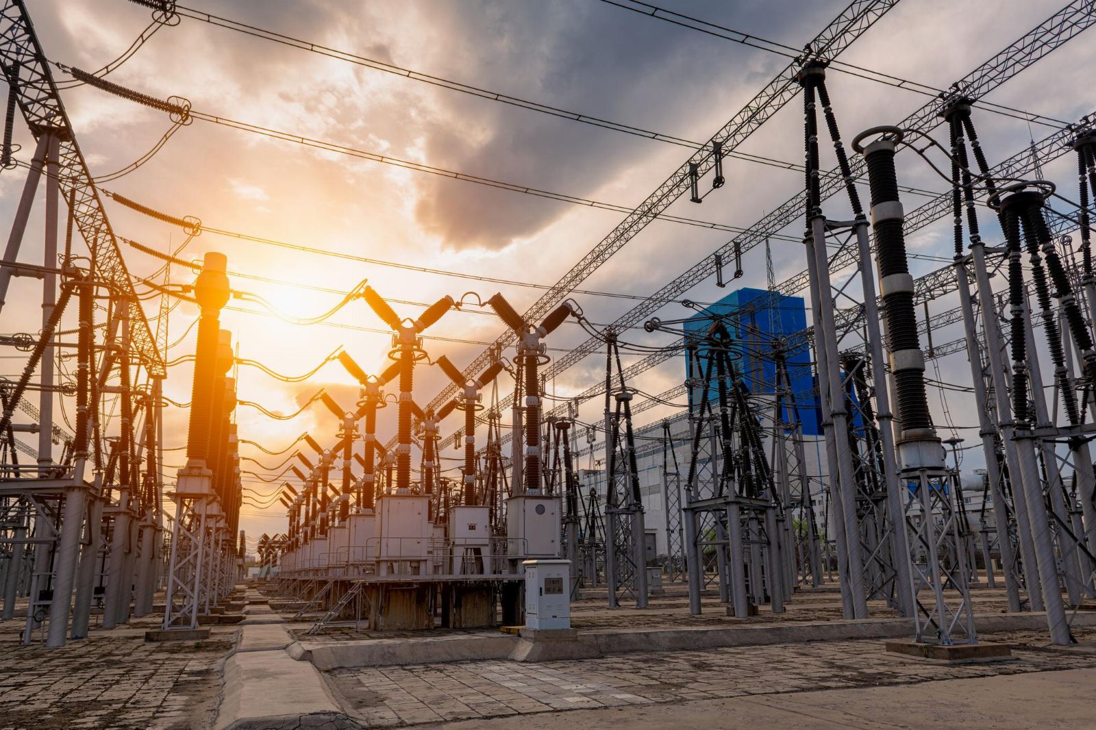
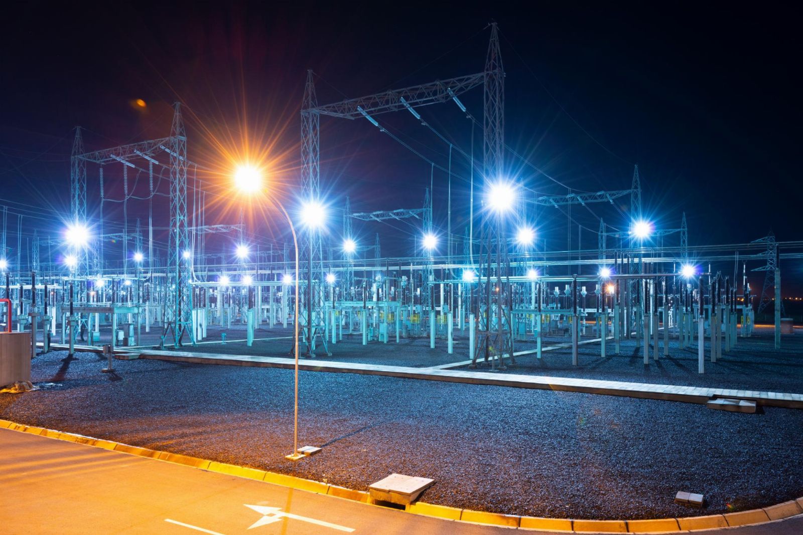
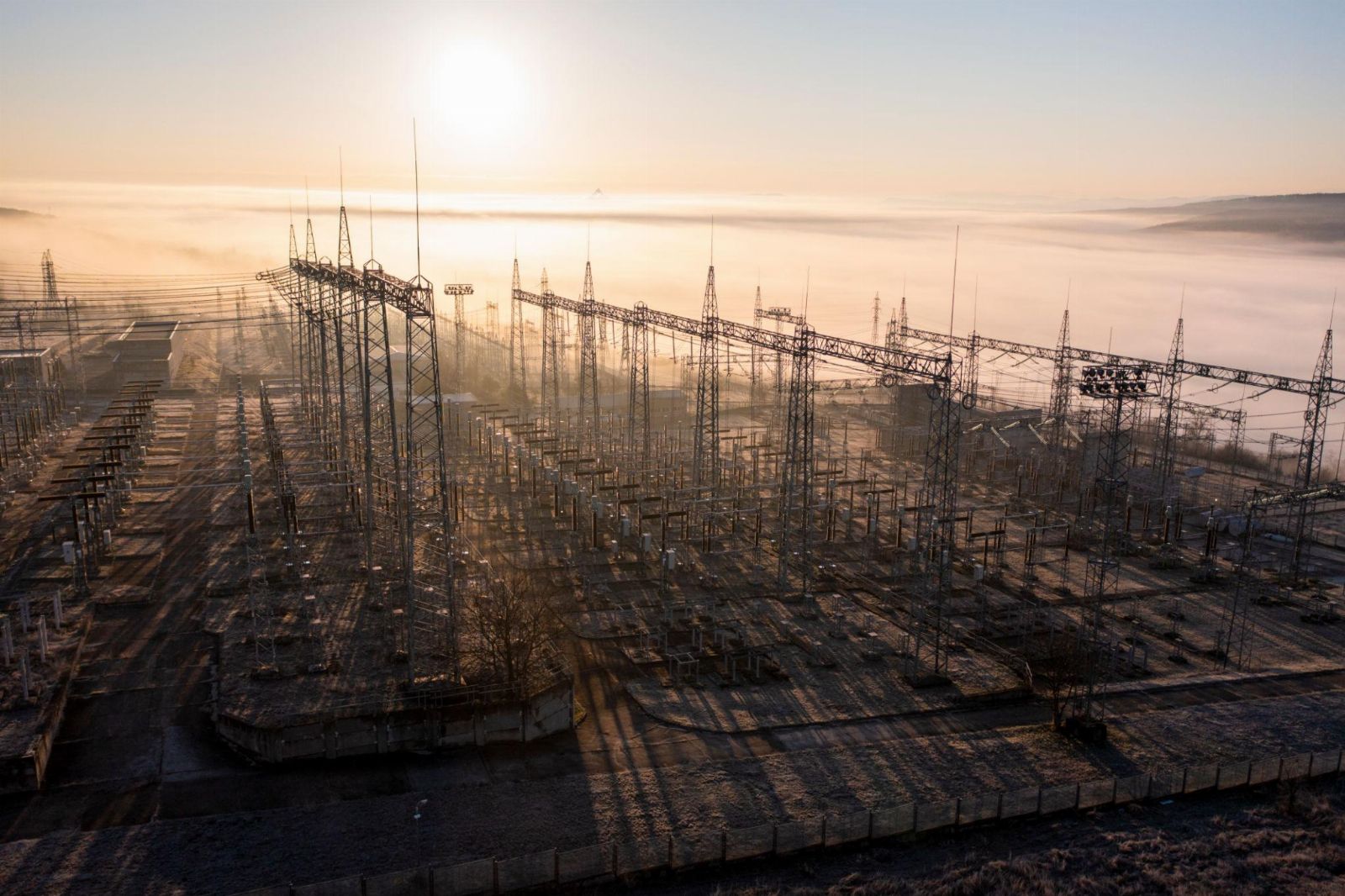
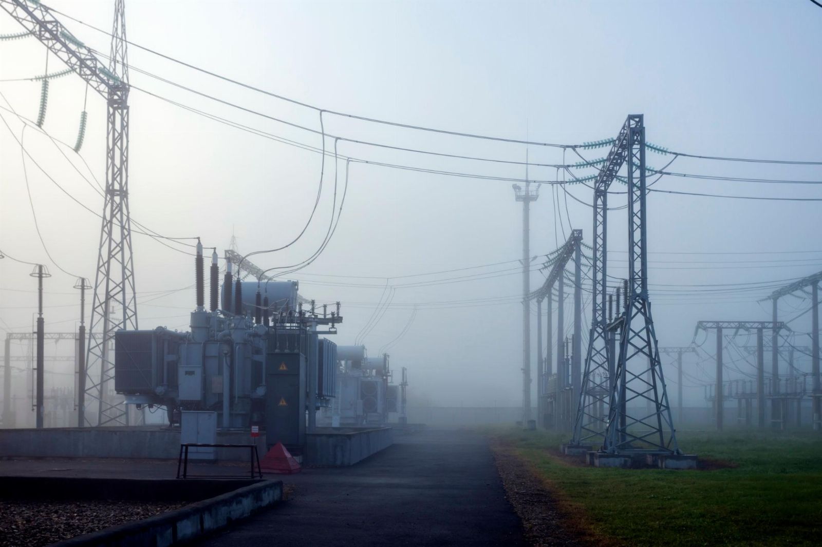
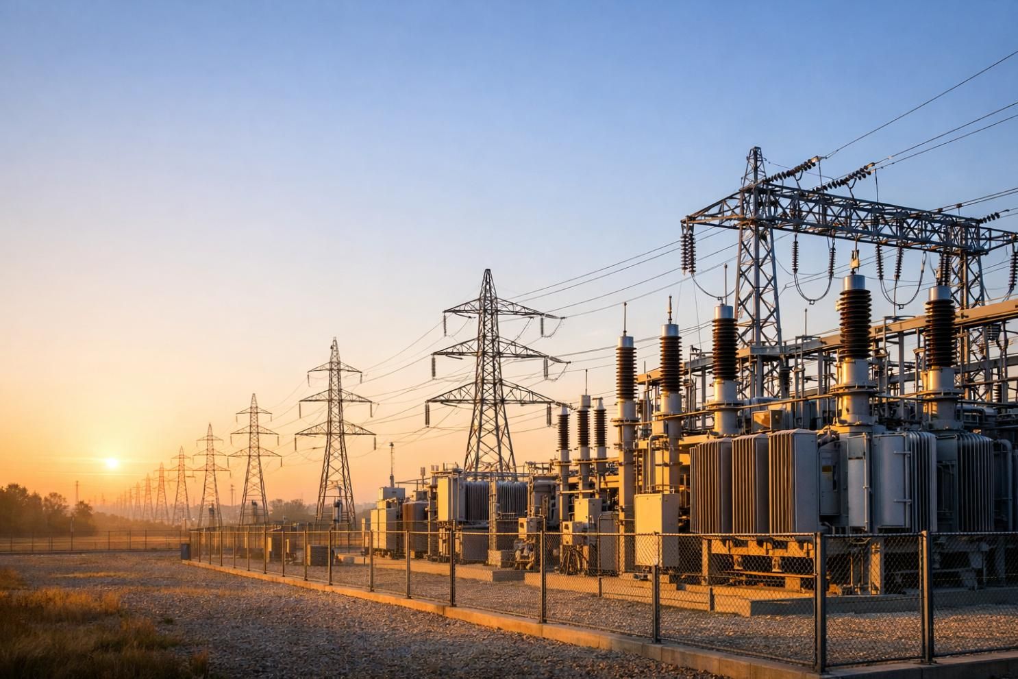
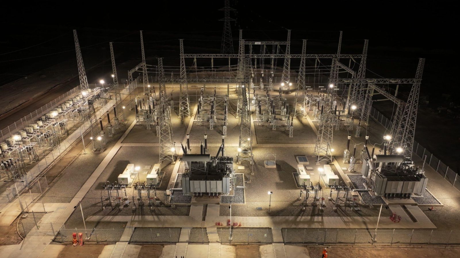
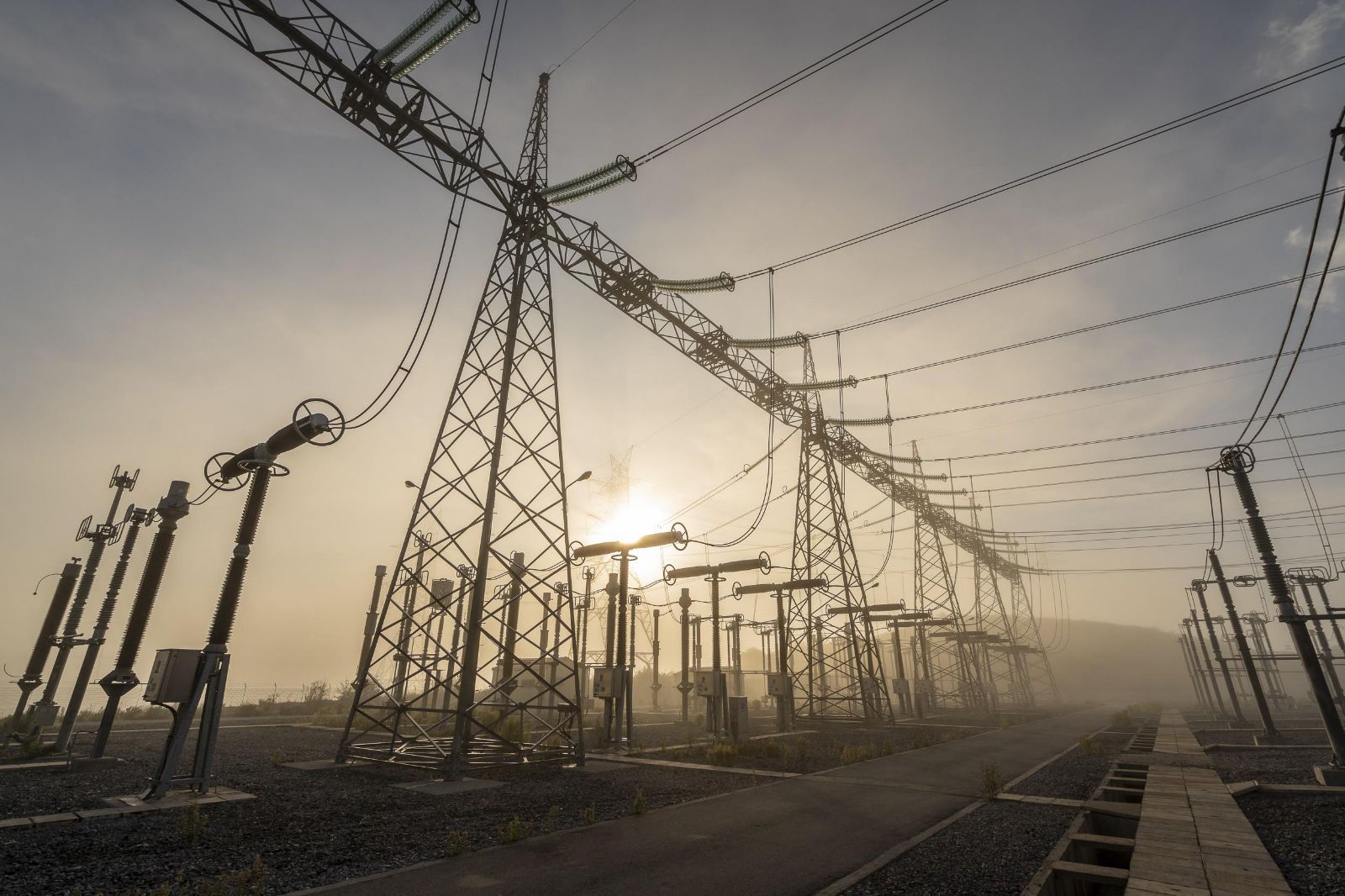
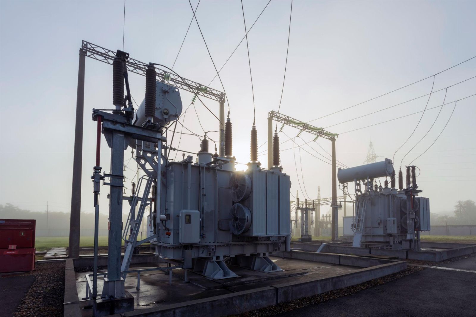
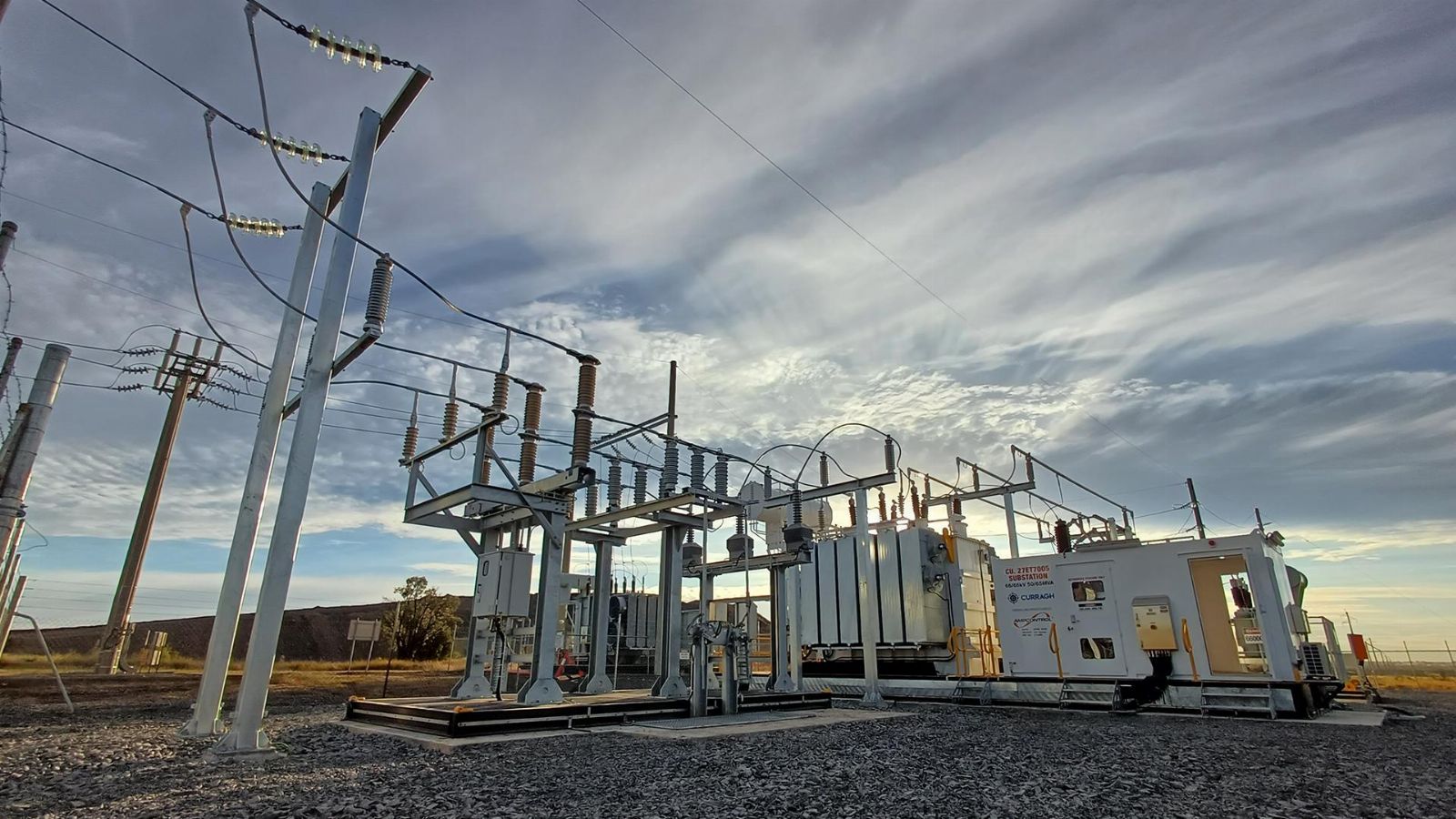
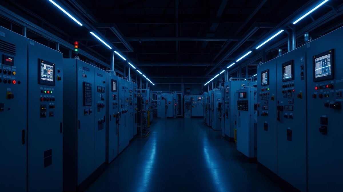
- We offer co-operation on replacement of old installed equipment on equipment at substations with new equipment produced at your factory. We have a large database of documentation for old, end-of-life equipment, and we will adapt your products to replace the old.

- Design of substation equipment in accordance with the technical specifications.

- Design documentation for the manufacture of electrical equipment.

- 3-D models, product drawings, BOM.

- Preparation of technical documentation for participation in tenders.

- Preparation of preliminary standards for material consumption for cost calculation..

- Consulting on projects.

..since August 1998

Proekt-Energo

Area of activity:

- Design of low-voltage, middle-voltage and high-voltage electrical equipment of substations for voltages of 0.4 - 220 kV.
- Development of working documentation in accordance with the technological capabilities of the plant.
- Preparation of preliminary technical documentation for participation in tenders for the supply of equipment.
- Consultations on project approvals.
- Supporting the production of equipment at the plant.

Specialization:

- Switchgear for indoor and outdoor installation for voltages of 6, 10, 20, 35 kV.
- Air-insulated secondary switchgears AIS for voltages 6, 10 kV.
- Complete transformer substations CTS for voltage 10 - 220 kV.
- Disconnectors for voltage 0.4 ... 220 kV.
- Drive to disconnectors.
- Replacement of withdrawable elements and switches in existing switchgear (Retrofit).
- Low-voltage switchgears for voltage 0.4 kV.
- DC 600V switchgears RU-600.

KSO-393 - 10 kV Single-front Medium-Voltage Metal-Enclosed Switchgear

The single-front medium-voltage switchgear KSO-393 (rated for 6–10 kV) is intended for receiving, distributing, and switching three-phase AC power at 50 Hz in systems with isolated or effectively earthed neutral. The series is designed for indoor air-insulated switchgear (AIS) of packaged transformer substations, for intake/distribution points at industrial facilities, for plant auxiliary switchgear of power stations, for municipal infrastructure, and other power supply systems. The cubicles can be installed both in permanent indoor substations and in rapidly deployable factory-built modular enclosures, which simplifies brownfield modernization and shortens commissioning times.

Purpose and application

Functionally, KSO-393 covers incomer, bus-section, and feeder connections of medium-voltage switchgear. Typical applications include: connection of 6–10 kV power transformers; switching of cable and overhead lines; busbar sectioning with the option of automatic transfer scheme; supply of process loads and plant auxiliaries; measurement, metering, and data transfer to monitoring systems and SCADA/DCS. Unified mating dimensions, transition panels, and coordinated busbar centerlines make it easy to integrate with existing boards during phased reconstruction. For new builds, standard modules allow quick configuration of the switchgear scheme for the required capacity and supply reliability category.

Service conditions

Cubicles are supplied for indoor, temperate, weather-protected locations - environmental category EN/IEC 60721-3-3 (replaces GOST 15150 U3). The design takes into account temperature, humidity, dust, as well as storage and transportation modes. The base degree of enclosure protection is IP20, preventing access to hazardous live parts and ingress of solid objects; local increases of IP in individual compartments are possible by design while maintaining thermal conditions and ventilation. For high-altitude sites, the effect of reduced air pressure on dielectric strength is considered and reflected in insulation clearances and acceptance test methods. For corrosive environments, enhanced coatings and corrosion-protection measures are applied, including galvanized or Al-Zn (Aluzinc) coated steel enclosures.

Layout and construction

The KSO-393 enclosure is available in two variants:
- a welded structural-steel frame with powder-polymer coating, designed for long-term mechanical and environmental durability;
- a bolt/rivet-assembled steel construction with Al-Zn (or Zn) coating on non-welded fasteners, focused on manufacturability and service convenience.

The internal space is divided into functional compartments. The busbar compartment houses main busbars and inter-panel links; the apparatus compartment contains the primary switching device (typically a vacuum circuit-breaker), disconnector, and earthing switch; the cable compartment contains cable terminations, current transformers, post insulators, and fixing hardware; a dedicated low-voltage compartment accommodates protection and control relays, meters, instruments, and marshalling panels. Viewing windows on the front allow visual confirmation of device positions. For maintenance, the cubicle includes internal lighting and a receptacle for a portable lamp.

The design provides rational placement of live parts, insulators, supports, and protective screens so that in plausible fault conditions products of an internal arc or gas release do not impose hazardous loads on personnel and do not cause insulation flashover to adjacent compartments. Required air and creepage distances are provided, along with measures to reduce local heat dissipation in high-current areas (bus joints, cable lugs, transition nodes).

Safety and interlocking

KSO-393 implements a comprehensive set of interlocks preventing hazardous or incorrect actions: blocking disconnector operation with the circuit-breaker closed; blocking closing of the earthing switch with the disconnector closed; blocking disconnector closing when the circuit is earthed; blocking door opening unless the circuit is earthed. Closed-door breaker operation is a fundamental safety principle that minimizes operator risk during any switching. Interlocks are implemented by mechanical, electrical, and, where required, electromagnetic means to ensure the prescribed sequence of operations. Optional arc-flash sensors and high-speed protection devices can be added to reduce incident energy during internal faults.

Versions and options

The KSO-393 series supports a wide set of configurations and options:
- selection of the primary switching device (vacuum circuit-breaker with required current and interrupting ratings; other options by agreement);
- manual and motor operators with remote control, telemetry, and telemetering;
- microprocessor-based protection relays: overcurrent/directional, differential and distance functions, autoreclose and automatic transfer, disturbance recording;
- instrument transformers (CTs/VTs) of required accuracy classes for protection and metering;
- internal arc classification (IAC) options with specified accessibility sides and directed energy relief to safe zones;
- enhanced anti-corrosion coatings, insulation/heaters, temperature monitoring of cable lugs and busbars, partial-discharge monitoring;
- seismic versions, extended spare-parts kits, standardized bus links, and transition panels for interfacing with other cubicle series.

Typical configurations

Common KSO-393-based configurations:
1) Incomer - connection of a power transformer or MV line, measurement and metering, optional automatic transfer;
2) Bus-section - bus sectioning to improve maintainability and contingency flexibility; variants with circuit-breaker or disconnector;
3) Feeder - outgoing cable and overhead lines equipped with protection and current/voltage monitoring;
4) VT/CT panel - auxiliary supply for measuring circuits, commercial/technical metering, system monitoring;
5) Plant auxiliaries - supply of DC/AC auxiliary power, control and life-support systems of the switchgear;
6) Bus coupler/tie - bus links and bypass connections between sections and busbars for flexibility during maintenance and expansions.

Compliance with standards (key norms)

  • IEC 62271-200 - AC metal-enclosed switchgear and controlgear (design, type tests, internal arc classification IAC).
  • IEC 62271-1 - Common specifications: service conditions, insulation levels, test methods.
  • IEC 62271-100 - AC circuit-breakers: interrupting capability, endurance, test duties.
  • IEC 62271-102 - AC disconnectors and earthing switches: drives, interlocking, mechanical endurance.
  • IEC 60529 - Degrees of protection (IP code) to justify IP20 / locally increased IP ratings.
  • EN/IEC 60721-3-3 - Environmental conditions for stationary use in weather-protected locations (replaces GOST 15150 U3 for climatic category).
  • IEC 60038 - Standard voltages; dielectric test levels as per the IEC 62271 series.
  • IEC 61869 (all relevant parts) - Instrument transformers (CTs/VTs) for protection and metering.

Engaging contractors, manufacturers, and investors

We offer cooperation to switchgear manufacturers, EPC contractors, and investors interested in localizing production of medium-voltage cubicles. The implementation package includes material and purchased-parts specifications, manufacturing instructions (cutting, bending, welding/non-welded assembly, painting), quality-control plans, cable schedules, and procedures for routine/functional tests. A phased transition is possible-from screwdriver assembly to full-cycle production of enclosures and busbars at your site. Staff training, process audits, and support of the first series reduce risks and accelerate certification.

Documents

A full set of design and shop documentation is provided for KSO-393: data sheets, single-line and functional diagrams, purchased-parts lists, assembly drawings and detailing, 3D models of assemblies and enclosures, cable schedules, and secondary connection diagrams. Popular formats are supported - AutoCAD (DWG/DXF), SolidWorks, Parasolid. Documentation is adapted to your component lineup, installed equipment (press brake, paint line, etc.), and corporate standards. Nameplate templates, labeling schemes, and packaging/transport recommendations can be provided as needed.

Operation and maintenance

The “closed-door breaker operation” concept is mandatory for safety and improves the predictability of switching. Modular architecture and unified parts shorten repair time and simplify spares management. We recommend regular checks of bolted joints and thermal conditions of high-current nodes, adjustment of protection settings to the current network configuration, and periodic verification of mechanical interlocks. For sites with high industrial-safety requirements, consider arc-flash protection, partial-discharge monitoring, and remote thermal monitoring of cable lugs and busbars.

Technical data

Rated voltage, kV 6; 10
Highest system voltage, kV 7.2; 12
Rated current of main circuits, A 630; 1250
Rated busbar current, A 630; 1250
Thermal short-time withstand current (3 s), kA 20
Peak withstand current (1 s), kA 51
Environmental category (replaces GOST 15150 U3) EN/IEC 60721-3-3
Degree of protection IP20 (IEC 60529)
Overall dimensions, mm
- width
- depth
- height

800
800
2400

- Preliminary technical package for tenders: data sheets, specifications, single-line and functional diagrams, equipment lists - for fast compliance checks and preparation of a commercial offer.
- Shop drawings, 3-D models, and a full design package to launch production at your site. If enclosure and busbar fabrication is not available in-house, we will arrange manufacturing at partner facilities; you perform final assembly, routine/acceptance tests, and installation.
- Rapid document updates to your project requirements and manufacturing capabilities; support for component procurement, supervisory installation and commissioning; preparation of insulation and functional test programs.

Benefits of working with us

- No need to maintain a large team of highly qualified engineers: the documentation set is structured for confident work by a mid-level engineer.
- Serial launch is possible without building a costly prototype, thanks to proven standard modules and validated solutions.
- Technical support at all stages - from adapting documents to your component lineup to commissioning support and preparation of O&M manuals.

For additional information on KSO-393, please contact: inbox@proekt-energo.com

Experience shows that an error made at the design stage leads to a multiple increase in costs during manufacturing and throughout operation. Correct specification of apparatus, competent design of busbar joints, and selection of instrument transformers with the required accuracy classes are the foundation of reliable and safe substation operation over its life cycle.

PDF - Download KSO-393 technical information

pdf

10 kV Single-Front Medium-Voltage Metal-Enclosed Switchgear (KSO-394)

Purpose and application

The KSO-394 series are modular medium-voltage switchgear cubicles for receiving, distributing, and switching three-phase AC power at 50 Hz with rated voltages of 6–10 kV. The equipment is suitable for systems with isolated or effectively earthed neutral and is used in indoor switchgear (AIS) of packaged transformer substations, at industrial and infrastructure substations, in auxiliary switchgear of power plants, as well as at municipal and transport facilities.

KSO-394 follows a “metal-enclosed, air-insulated (AIS)” concept: all live parts are housed in a metallic enclosure; insulation is air with proven post insulators and bushings. This simplifies maintenance and lowers lifecycle cost versus gas-insulated solutions while maintaining high operational readiness.

Service Conditions

Base environmental category - EN/IEC 60721-3-3 (indoor, weather-protected). On request, variants for other environmental categories are available, including cold climates, tropical design, and enhanced corrosion resistance. Typical enclosure protection degree - IP20 to IEC 60529. For dusty rooms, reinforced protection of specific compartments and installation of ventilation filters can be provided.

Rated voltage levels align with standard series: 6 kV (Ur = 7.2 kV) and 10 kV (Ur = 12 kV). Design solutions ensure compliance with normative lightning/switching overvoltage levels as well as mechanical effects arising during short-circuit currents.

Layout and Construction

The frame is available in two variants:

  • Welded steel frame with powder-polymer coating - optimal for most industrial and power facilities; provides high resistance to abrasive and chemical exposure.
  • Rivet-bolted steel enclosure with alu-zinc (or zinc) coating - enhanced corrosion resistance; ensures stable geometry in serial production.

The internal layout is traditionally divided into compartments: apparatus (withdrawable or fixed), busbar, and cable. This separation improves safety (localizes fault effects), eases access for maintenance, and reduces commissioning time. In the base version, all controls are accessible from the front (single-front service). The front includes viewing windows and mechanical position indicators of drives.

The cable compartment is arranged for bottom entry (top entry available by design). Connections are made via appropriate class cable terminations; installation of current and voltage transformers, arc-flash sensors, and temperature sensors for condition monitoring is supported. Internal service lighting is standard: a lamp holder and a socket outlet for a portable lamp; the switch is on the front. Lamp replacement is safe and does not require de-energizing main or auxiliary circuits.

Safety and Interlocking

KSO-394 is equipped with a set of mechanical and electrical interlocks preventing hazardous operations and typical human errors, including:

  • interlock preventing disconnector operation with the circuit-breaker closed;
  • interlock preventing earthing switch closing with the disconnector or circuit-breaker closed;
  • interlock prohibiting truck racking-out with the circuit-breaker closed;
  • interlock preventing opening of medium-voltage compartments’ doors unless the earthing switch is closed;
  • option for trapped-key interlocking and inter-section logic.

All circuit-breaker operations are performed with the door closed, reducing risks during switching. For enhanced operational safety, voltage presence indication systems (VDIS) with an LRM interface can be installed for portable detectors and built-in interlocking logic.

On request, internal arc solutions are implemented: directed gas relief, reinforced latches and hinges, PM/PI partitioning rated for the specified arc current and protection clearing time. The specific IAC classification is assigned after type-testing of the configured panel.

Versions and Options

  • Switching devices. Vacuum medium-voltage circuit-breakers are used as the main device with the required interrupting ratings. For special tasks, load-break switches, contactors, or “switch-fuse” combinations can be applied.
  • Protection and automation. Microprocessor-based protection relays, AR/ATS devices, SCADA/telecontrol panels, and power-quality meters are available. Integration via standard protocols (incl. IEC 60870-5-104/IEC 61850) and implementation of special protection schemes are supported.
  • Measurement and metering. Current/voltage transformers of required accuracy classes, metering cabinets, and modular measurement panels can be installed.
  • Condition monitoring. Optional predictive diagnostics: temperature sensors on cable lugs and busbars, partial discharge sensors, arc-flash sensors with fast local tripping.
  • Corrosion resistance. Enclosures can be made from powder-coated steel or alu-zinc coated steel; selection depends on site corrosion category and service-life requirements.
  • Seismic and fire safety. Versions with calculation/testing to the specified seismic category are available, as well as the use of non-combustible insulation and cable fire-stopping.

Typical Configurations

The KSO-394 range covers the full set of typical indoor AIS panels: incomers/sectionalizers with a circuit-breaker, feeder panels, transformer feeder panels, measuring and tie panels. Based on unified schemes (e.g., “incoming-section-feeder”, “incoming-transformer”), switchboards of the required capacity and supply reliability category are easily formed. Where necessary, compatibility can be provided for mating dimensions and interlocking logic with existing KSO-series (incl. KSO-3xx) using transition panels.

Configurations may include bus bridges, bus section disconnectors, bypass and measuring panels, cable test facilities, and sections with independent interlocking logic to improve maintainability (LSC categories up to LSC2B - project-specific).

Compliance with Standards

Design and manufacturing of KSO-394 comply with applicable international and national standards. Depending on selected configuration and devices, the following standards are relevant:

  1. IEC 62271-200 - AC metal-enclosed switchgear and controlgear above 1 kV and up to 52 kV (LSC categories, PM/PI partitions, IAC classification).
  2. IEC 62271-1 - Common specifications for high-voltage switchgear and controlgear.
  3. IEC 62271-100 - AC circuit-breakers for medium voltage.
  4. IEC 62271-102 - Disconnectors and earthing switches.
  5. IEC 62271-105 - Switch-fuse combinations.
  6. IEC 62271-213 - Voltage presence indication systems (VDIS) and LRM interface.
  7. IEC 61869-2 and related parts - Instrument transformers (CTs/VTs).
  8. IEC 60038 - Standard voltages; EN/IEC 60721-3-3 - environmental conditions for stationary use in weather-protected locations; IEC 60529 - Degrees of protection (IP code).
  9. EN 10346 - Continuously alu-zinc/zinc coated steel flat products (for relevant enclosure versions).

Engaging Contractors, Manufacturers, and Investors

We are open to cooperation with manufacturers of switchgear devices, metal structures, and semifinished products, as well as contractors (installation, commissioning, service) and investors interested in localization and serial production of KSO-394. Flexible collaboration models are available:

Documents

  • Pre-tender package: single-line diagrams, equipment lists, questionnaires, standards compliance matrices, 3D visualizations, and a technical note. The package helps objectively evaluate manufacturability within the required schedule and budget.
  • Manufacturing drawings: assembly drawings, main and auxiliary circuit schematics, bills of materials, cable schedules. Formats - DWG/DXF (AutoCAD), STEP/Parasolid; models for SolidWorks/Inventor.
  • Interlocking schemes and algorithms: inter-panel and intra-panel logic, trapped-key interlocking, conditions tables, and tolerance matrices. The schemes reflect the sequence of safe operations and are suitable for staff training.
  • Commissioning & O&M instructions: checklists, crimping/torque programs, insulation test methods, control-circuit checks, and preventive maintenance routines.
  • Make/buy cooperation: if in-house capacities are limited, assistance with outsourcing enclosure parts, busbar systems, harnesses, and mounting panels to third-party plants under your technology.

Additional Technical Notes

Thermal withstand under short-circuit current characterizes the ability of live parts to endure heat release for the specified time without exceeding permissible temperatures and without residual deformations that impede operation. Dynamic withstand is the ability to withstand electrodynamic forces in the initial short-circuit period (peak current) without displacement and mechanical damage to bus bridges and fasteners.

Protection settings are chosen using calculated short-circuit currents at the point of installation, considering the network topology and impedances of transformers, cables, and busbars. Final current values and protection clearing times are coordinated with the selected switching devices and their time-current characteristics, as well as with the strength of live parts and busbar systems.

Particular attention is paid to EMC: proper routing of secondary harnesses, shielding, and standardized bonding jumpers reduce interference and improve the immunity of digital protection and control. To enhance maintainability, we use terminal marking, service loops in cable management, and standardized interfaces for the telecontrol panel.

Technical data

Номинальное напряжение, кВ 6; 10
Наибольшее рабочее напряжение, кВ 7,2; 12
Номинальный ток главных цепей, А 400; 630
Номинальный ток сборных шин, А 630
Ток термической стойкости при длительности протекания 3 с, кА 20
Ток динамической стойкости при длительности протекания 1 с, кА 51
Климатическое исполнение и категория размещения по ГОСТ 15150  У3
Степень защиты по ГОСТ 14254 IP20
Габаритные размеры, мм
- ширина
- глубина
- высота

800
800
1900; 2000

We prepare a complete set of engineering documentation - from the tender package to manufacturing drawings and commissioning manuals - adapted to your project requirements, selected device lineup, and production capabilities. If in-house fabrication of certain assemblies is not planned, we will help organize cooperation with third-party manufacturers: enclosure parts, busbar systems, harnesses, control panels, etc.

  • Tender package: single-line diagrams, specifications, questionnaires, standards compliance matrices, 3D models/renders, and an explanatory note for estimating effort and cost.
  • Working documentation: assembly drawings, primary and secondary schematics, bills of materials, cable schedules, harness tying sheets. Formats - DWG, DXF, STEP, Parasolid; models - for AutoCAD, SolidWorks, Inventor.
  • Interlocking schemes and algorithms: sequence of safe operations (close/open/earth/rack-out/access), inter-panel trapped-key logic, signal/condition tables.
  • VDIS and arc-flash integration: wiring diagrams, test procedures, staff briefing, inclusion into overall protection and telecontrol logic.

Benefits of Working with Us

No need to maintain a large engineering staff: our documentation set enables starting serial production without costly prototypes. Your specialists receive guidance on all manufacturing and commissioning nuances, including fastener selection, torque charts, quality control of welded and bolted joints, labeling, and harness routing.

For additional information on KSO-394, contact: inbox@proekt-energo.com

…and, as is well known, an error made in design results in tenfold costs in manufacturing and a hundredfold in operation. Choose proven solutions and standardized assemblies.

PDF - Download KSO-394 Technical Information

pdf

Single-Front Metal-Enclosed Medium-Voltage Switchgear 10 kV, Type KSO-399

Purpose and application

KSO-399 single-front metal-enclosed (AIS) medium-voltage switchgear is intended for the reception, distribution and switching of electrical energy in three-phase 50 Hz AC networks with rated voltages of 6–10 kV. The panels are used to feed load centers, protect feeders and transformers, sectionalize busbars and ensure operational reliability at power, industrial, transport and utility facilities. The design belongs to the air-insulated, metal-enclosed class (AIS), combining maintainability, intuitive operation and a moderate life-cycle cost.

Typical applications include indoor substations (MV switch rooms) of package transformer substations, power-plant auxiliary switchgear, substations of industrial and infrastructure sites, as well as supply centers for residential and commercial developments. The single-front (front-access) concept allows rows of panels to be placed along a wall or in constrained rooms, providing access to all controls from the front and reducing installation-space requirements.

Service Conditions

Baseline environmental category - per EN/IEC 60721-3-3 (indoor, weather-protected locations). Other categories can be supplied on request (including options comparable to U1/U2, UHL) as well as versions for higher corrosion categories. The typical enclosure degree of protection is IP20 per IEC 60529; higher local protection for specific compartments, dust filters and screens can be provided on request. The construction ensures mechanical and thermal withstand under short-circuit currents and resistance to standard indoor environmental factors of MV switch rooms.

Rated voltage levels follow the standard series: 6 kV (highest voltage 7,2 kV) and 10 kV (highest voltage 12 kV). Insulation levels are selected to withstand lightning and switching overvoltages and to provide adequate air clearances in accordance with safety and dielectric-strength requirements.

Configuration and Design

KSO-399 features a modular layout with clearly separated compartments: apparatus, cable and busbar. This segregation increases safety, localizes potential fault effects, speeds installation and simplifies maintenance. All operating controls are accessible from the front; viewing windows, mechanical position indicators and ergonomic operators are provided. Internal lighting is implemented by a built-in lamp with a socket and a front-mounted switch, plus an outlet for a portable lamp. The lamp can be replaced safely without de-energizing main or auxiliary circuits.

The frame and enclosure are available in two manufacturing options:

  • Welded steel frame made of structural steels with powder-polymer coating, providing high rigidity, dimensional stability and resistance to abrasive and chemical exposure typical for indoor MV rooms.
  • Non-welded steel body with AluZinc (or zinc) coating using riveted/bolted joints - for sites requiring enhanced corrosion resistance and dimensional repeatability in serial production.

The cable compartment is designed for bottom entry of power cables; top entry is available if required. Space is provided for current and voltage transformers of required accuracy classes, temperature sensors and arc-flash sensors for fast protection systems, as well as for proper cable clamping with controlled bending radii and convenient service loops.

To unify assembly, the design provides standard mounting holes, inserts for components from different manufacturers, and standard locations for microprocessor protection relays, SCADA/telecontrol panels and local control units.

Safety and Interlocking

KSO-399 is engineered for safe operation throughout its life cycle. A set of mechanical and electromechanical interlocks prevents hazardous actions:

  • blocking of disconnector operations when the circuit-breaker is closed;
  • blocking of the earthing switch when the disconnector or breaker is closed;
  • blocking of truck withdrawal when the breaker is in the closed position;
  • blocking of HV-compartment doors unless the earthing switch is closed;
  • provision for trapped-key interlocks and inter-section logics.

All breaker operations are performed with the door closed, reducing switching risks. Ducts, guides and pressure-relief flaps route gases safely in case of an internal fault, minimizing impact on personnel and adjacent panels.

Versions and Options

  • Main switching device. Vacuum circuit-breakers (MV) with required continuous and short-circuit ratings as standard. Load-break switches, contactors or switch-fuse combinations can be installed for specific duties.
  • Protection and control. Modern microprocessor relays for feeders, transformers and bus sections; automatic transfer and auto-reclosing (ATS/AR); telecontrol/SCADA with communication protocols (incl. IEC-compatible); local control panels.
  • Measurement and metering. Current and voltage transformers with metering and protection classes; energy meters, power-quality panels, measuring modules with data logging.
  • Arc-flash and thermal protection. Arc sensors, high-speed tripping schemes, temperature sensors on cable terminations and busbars with output to the diagnostic system.
  • Voltage presence indication. Integration of stationary indicators (VDIS) with front-panel display and test-point interface.
  • Enclosure modifications. Two-coat powder painting; AluZinc/zinc coating for extended durability; options with reinforced door hardware and multi-point rod locks for high-vibration sites.
  • Seismic and fire safety. Equipment supplied with calculation and/or testing to the specified seismic category; use of non-combustible insulation materials and fire-rated cable glands and seals.

Typical Configurations

The KSO-399 lineup covers all common MV switchboard panels: incoming and bus-section panels with a breaker, line feeders, transformer feeders, metering and coupling panels, as well as spare bays for future expansion. Based on unified schemes (e.g., “incoming - section - feeder”, “incoming - transformer”), complete switchboards are assembled to the required power and supply-reliability category. Transition panels can be used to interface with previously installed KSO series (including KSO-3xx) without changing room geometry.

To increase maintainability, selections are made with regard to LSC categories and partition classes PM/PI, allowing work in individual compartments without de-energizing adjacent feeders (within the chosen category). Solutions are available for bus bridges, bypass and measuring circuits, as well as for cable testing via dedicated sockets/plugs in the cable compartment.

Standards Compliance

Design and manufacture of KSO-399 comply with relevant international and national standards. Depending on configuration and fitted apparatus, the following documents are taken into account:

  1. IEC 62271-200 - AC metal-enclosed switchgear and controlgear for rated voltages above 1 kV and up to and including 52 kV (LSC categories, partition classes PM/PI, internal-arc requirements).
  2. IEC 62271-1 - general requirements for switchgear and controlgear (series title: “High-voltage switchgear and controlgear”).
  3. IEC 62271-100 - AC circuit-breakers (medium-voltage).
  4. IEC 62271-102 - disconnectors and earthing switches.
  5. IEC 62271-105 - switch-fuse combinations.
  6. IEC 61869 (series) - instrument transformers (current and voltage).
  7. IEC 60038 - standard voltages.
  8. EN/IEC 60721-3-3 - classification of environmental conditions (indoor, weather-protected); IEC 60529 - degrees of protection (IP code).

Partnering with Contractors, Manufacturers and Investors

We welcome technology partnerships with manufacturers of switchgear apparatus, metal structures, cable and busbar systems, as well as with installation and service companies. Various cooperation models are available: supply of metal kits and spare-parts sets, licensing of production documentation, outsourcing of assemblies (enclosures, withdrawable trucks, harnesses, mounting panels), joint preparation and conduct of qualification/type tests, and customer staff training. For investors, serial production of KSO-399 can be localized under a specific regional grid-infrastructure program.

When establishing cooperation, we provide route cards, quality-control plans, tooling lists and fastener standards, corrosion-protection and powder-coating recommendations, as well as incoming-inspection procedures for purchased items.

Documents

  • Tender package: single-line diagrams, equipment lists, data sheets, compliance checklists, 3D visuals and an explanatory note for quick, objective assessment of effort and budget.
  • Manufacturing documentation: assembly drawings, BOMs, main and auxiliary circuit schematics, cable schedules, purchased-parts lists. Formats - DWG, DXF, STEP, Parasolid; models - for AutoCAD, SolidWorks, Inventor.
  • Interlocking schemes and logic: safe-operation sequences (close/open, earthing, truck movement, access), trapped-key interlocks, signal/condition matrices.
  • Commissioning and O&M instructions: checklists, insulation-test programs, control-circuit verification, maintenance routines, torque charts and lists of inspection measurements.
  • Co-manufacturing of assemblies and parts: contractor selection for enclosures, busbar systems, harnesses and mounting panels; tolerance, coating and marking alignment.

Additional Technical Notes

Thermal withstand under short-circuit current characterizes the ability of live parts to dissipate heat over a specified time without exceeding permissible temperatures and without deformation that would hinder normal operation. Dynamic (peak) withstand reflects resistance to electrodynamic forces at the initial short-circuit moment (peak current) and defines requirements for busbar rigidity, fasteners and insulating supports. These parameters are selected on the basis of short-circuit studies at the installation point and coordinated with protection time–current characteristics and the interrupting capability of the main apparatus.

To ensure electromagnetic compatibility (EMC), secondary harnesses are routed with separation between power and signal circuits; shielded cables are used; earthing is arranged to avoid stray currents and induced voltages. Terminal and cable marking follows the operation and maintenance documentation to simplify service.

Technical data

Rated voltage, kV 6; 10
Highest voltage for equipment, kV 7,2; 12
Rated current of main circuits, A 400; 630
Rated busbar current, A 630
Short-time withstand current (3 s), kA 20
Peak (dynamic) withstand current (1 s), kA 51
Environmental category (placement) EN/IEC 60721-3-3
Degree of protection per IEC 60529 IP20
Overall dimensions, mm
- width
- depth
- height

800
800
2200

We provide a complete set of engineering documentation - from a preliminary package for tenders to production documentation for serial manufacture and commissioning. The package is adapted to project requirements, selected apparatus and your plant’s manufacturing capabilities. If self-manufacture of some parts and assemblies is not planned, we will help organize co-production at external facilities: enclosure parts, busbar systems, withdrawable trucks, harnesses, mounting panels and more.

  • Pre-tender technical documentation: single-line diagrams, equipment lists, data sheets, compliance checklists, 3D models/visuals, explanatory note with effort and schedule estimates.
  • Working drawings and 3D models: assembly drawings, BOMs, main and secondary circuit schematics, cable journals, purchased-parts lists. Formats - DWG, DXF, STEP, Parasolid; models - for AutoCAD, SolidWorks, Inventor.
  • Interlocking schemes and algorithms: sequences for safe operations (close/open, earthing, truck movement, access), inter-panel trapped-key interlocks, signal/condition matrices.
  • Commissioning and operation manuals: checklists, insulation-test programs, control-circuit verification, maintenance procedures, torque charts and a list of control measurements.
  • Co-manufacturing of parts and assemblies: contractor selection, alignment of tolerances, coatings and marking; preparation of route cards and quality-control plans.

Why Work with Us

There is no need to maintain a large team of highly qualified engineers: our documentation set enables a mid-level engineer to organize production without costly prototypes. At every stage - from selecting parameters and specifications to launching serial production - your specialists receive guidance on assembly nuances, electrical tests, harness routing, terminal marking and connection-quality control.

For additional information on KSO-399, please contact: inbox@proekt-energo.com

…and as is well known, an error made at the design stage results in tenfold costs in manufacturing and a hundredfold in operation. Rely on correct standards, proven assemblies and competent co-production.

PDF - Download KSO-399 Technical Information

pdf

::contentReference[oaicite:0]{index=0}

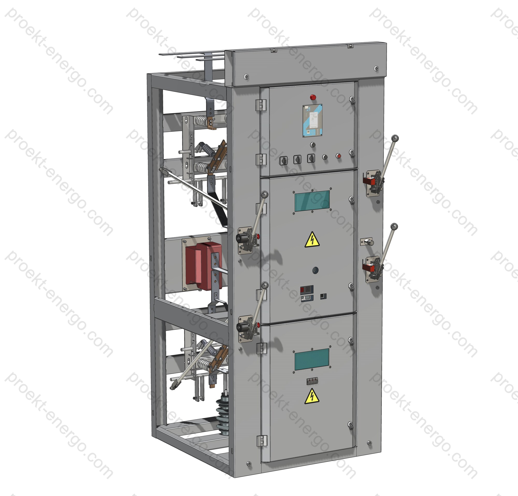
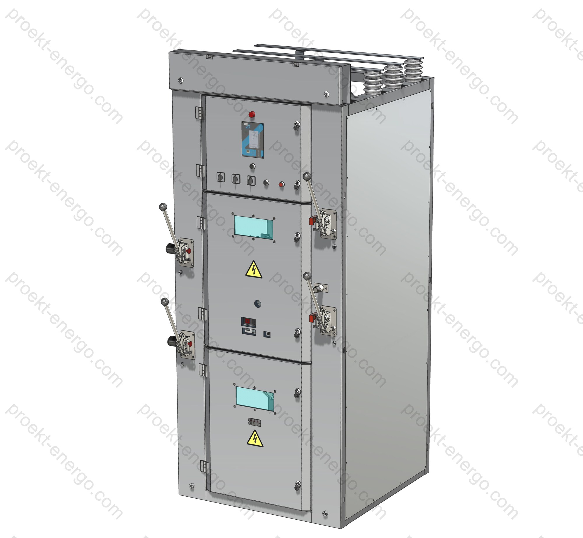
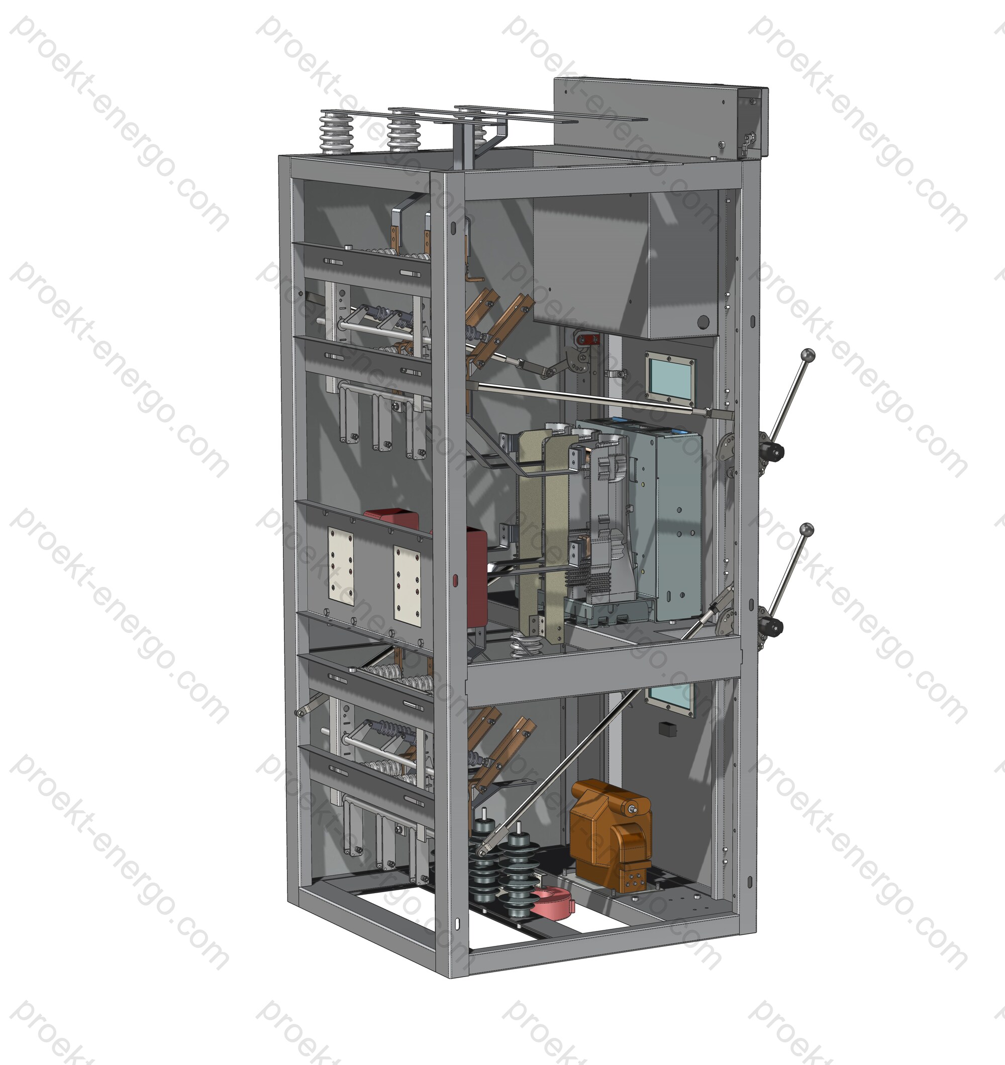
Single-front medium-voltage switchgear 10 kV, type KSO-366

KSO-366 is a family of single-front medium-voltage (6–10 kV) switchgear panels designed for the reception, distribution, and dependable switching of three-phase 50 Hz AC. The panels operate in systems with isolated or earthed neutral and are installed indoors in metal-enclosed switchrooms of unit substations, at industrial sites, in auxiliary switchgear of power plants, and on municipal and transport infrastructure facilities. The design is optimized for fast installation: panels are equally at home in permanent switchrooms and factory-built modular buildings, which simplifies refurbishment of existing substations and accelerates commissioning of new assets.

Purpose and application

KSO-366 forms incoming, bus-section, and feeder connections in 6–10 kV switchgear lineups. The series covers intake from power transformers, connection of cable/overhead lines, busbar sectionalizing with automatic transfer schemes, auxiliary services, and metering/measurement functions. Unified connection dimensions and available adapter panels allow new panels to be tied into existing busbars and cable routes with minimal outages. For new builds, standard one-line and functional schemes shorten engineering time and ease approvals.

Service conditions

The base design is for indoor installation in temperate climates (indoor locations). The construction tolerates the specified ranges of temperature and humidity and permits storage/transport without damage to coatings and insulation. Enclosure degree of protection - IP20, preventing accidental access to live parts and ingress of large solid objects. On request, individual compartments can be supplied with locally increased IP, subject to verification of thermal conditions and ventilation. For high-altitude sites, clearances and test regimes are adjusted; in corrosive atmospheres, enhanced coatings and Aluzinc/galvanized steel components are applied.

Layout and design solutions

Panel structures are manufactured in two concepts:
- Welded frame of structural steel with durable powder-polymer coating - for maximum mechanical rigidity and long life under heavy duty;
- Bolted sheet-metal enclosure made of steel with Aluzinc (or zinc) coating on non-welded fasteners - for rapid assembly, serviceability, and clean joint geometry.

Each panel is divided into functional compartments: busbar compartment (main busbars and inter-panel links), apparatus compartment (main switching device, disconnector and earthing switch), cable compartment (entries, terminations, current transformers, supports and cable cones), and the low-voltage compartment (protection/automation IEDs, terminal blocks, measuring instruments). Viewing windows on the front enable visual status checks. Built-in task lighting and a socket for a portable lamp allow safe routine operations while keeping main and auxiliary circuits energized, provided accepted procedures are followed.

The arrangement of live parts and barriers is chosen to reduce the probability of flashovers during transients and to direct any arc-fault products into safe zones. High-current joints (busbar contacts, cable lugs) are designed for low losses and stable thermal behavior. The design documentation provides access to components subject to routine maintenance.

Safety and interlocking

Interlocking prevents hazardous actions by personnel. It is prohibited to: operate the disconnector with the circuit-breaker closed; close the earthing switch with the disconnector closed; close the disconnector onto an earthed feeder; open doors when the feeder is not earthed. Breaker operation is performed with the door closed - this is a basic safety principle. Interlocks are implemented by mechanical means and electrical position monitoring and can be supplemented with arc-flash sensors and high-speed trip functions. This architecture reduces the likelihood of injury and limits the consequences of internal faults.

Configurations and options

The series supports a wide range of configurations: incoming, bus-section (with circuit-breaker or disconnector), feeder, VT/CT panels, metering and auxiliary services, as well as bus couplers. Options include:
- selection of circuit-breaker type and operating mechanisms (manual/motor), fixed or withdrawable arrangements;
- microprocessor protection and automation IEDs (overcurrent, directional, differential, distance functions, reclosing/automatic transfer, event recording);
- measuring current/voltage transformers with accuracy classes for protection and revenue metering;
- enhanced internal arc resistance with directed energy relief and protective screens;
- extended anti-corrosion coatings, thermal insulation and heaters, busbar and cable-lug temperature sensors, partial-discharge monitoring;
- standardized busbar links, recommended spare-parts kits, and transition panels for interfacing with earlier series.

Typical 6–10 kV lineup configurations

Incoming - intake from OHL/Cable or from a power transformer, measurement and metering, optional ATS;
Bus-section - splitting busbars into sections to improve maintainability and fault-ride-through (variants with circuit-breaker or disconnector);
Feeder - outgoing cable/overhead feeders with a full protection suite and diagnostics;
VT/CT panel - supply of measuring circuits, technical/commercial metering, condition monitoring;
Auxiliary services - supply of control power and switchroom life-support systems;
Bus coupler - busbar links and bypass arrangements between sections/ducts.

Compliance and normative references

  • Metal-enclosed medium-voltage switchgear: design rules, type and routine tests, internal-arc classification (IEC 62271-200).
  • General requirements for medium-voltage switchgear and controlgear: service conditions, insulation levels, electrical and mechanical tests (IEC 62271-1).
  • AC switching devices: performance, making/breaking capability, and test duties (e.g., circuit-breakers - IEC 62271-100).
  • Disconnectors and earthing switches: requirements for drives, interlocking, and endurance (IEC 62271-102).
  • Degrees of protection by enclosures (IP code): selection of IP20 and locally increased IP by zone (IEC 60529).
  • Environmental conditions - classification for stationary use in weather-protected locations (EN/IEC 60721-3-3).
  • Dielectric withstand: power-frequency and impulse tests confirming clearances and creepage (per IEC 62271-1/-200).
  • Instrument transformers: accuracy classes and loading for protection and metering (IEC 61869-2/-3).

Operation and maintenance

The “operate with the door closed” principle reduces risk during switching and improves predictability of switchgear behavior. Recommended practices include periodic inspection of bolted joints and terminals, thermal monitoring of high-current points, verification of interlock functionality, and updating of protection settings to suit network conditions. Modularity and unified components reduce downtime during repairs and simplify spare-parts logistics.

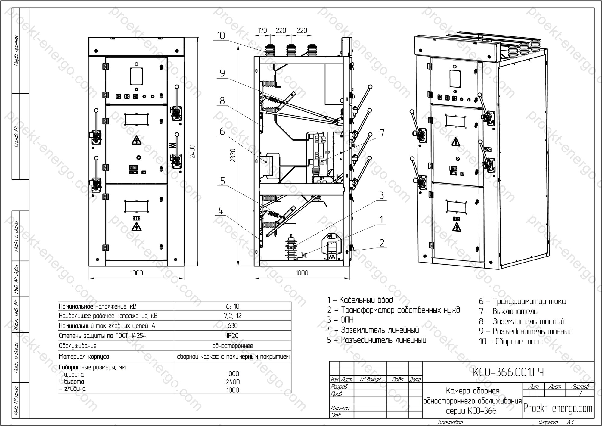
Technical data

Rated voltage, kV 6; 10
Maximum system voltage, kV 7.2; 12
Rated current of main circuits, A 400; 630
Rated busbar current, A 630
Thermal withstand current for 3 s, kA 20
Dynamic withstand current for 1 s, kA 51
Environmental classification and installation category per EN/IEC 60721-3-3 Indoor
Degree of protection per IEC 60529 IP20
Overall dimensions, mm
  - width
  - depth
  - height

1000
1000
2400

Documents

- Preliminary package for tenders: data sheets, one-line and functional diagrams, specifications and equipment lists - for rapid compliance checks and preparation of commercial offers.
- Full set of design documentation and 3D models to launch production at your site. If your busbar/enclosure capacity is limited, we can arrange fabrication at partner facilities; assembly, routine tests and installation are performed at your works.
- Manufacturing adaptation: prompt updates to drawings for your processes, component sourcing support, supervision of assembly and commissioning, and preparation of insulation and functional test programs.

Why work with us

- Reduced workload on in-house engineers: documentation is structured so that a mid-level engineer can work with confidence.
- Fast ramp-up to series: proven modules and repeatable solutions eliminate lengthy pilot iterations.
- Expert support: assistance with component selection, protection IED configuration, preparation of O&M documents, and staff training.

For additional information on KSO-366 please contact: inbox@proekt-energo.com

Practice shows that errors made at the design stage multiply fabrication and lifecycle costs. Careful specification of switching devices, correct selection of instrument transformers, and a well-thought-out busbar system are the basis for safe, reliable substation operation throughout its life.

PDF - Download KSO-366 technical information

pdf

Single-front medium-voltage switchgear 10 kV KSO-272

The single-front metal-enclosed switchgear KSO-272 is designed for operation in 6–10 kV systems to receive, distribute, and protect three-phase 50 Hz AC circuits. Typical applications include MV switchrooms at industrial plants and energy facilities, transformer substations, power stations, public-utility infrastructure, as well as factory-built modular indoor substations. The cubicle design emphasizes safe operation, service convenience, and straightforward integration into existing switchgear lineups.

Purpose and application

KSO-272 panels provide reliable power distribution and network protection against overloads and short-circuits. They are installed in 6–10 kV distribution bays and package transformer substations (PTS), at industrial power sites, in municipal power infrastructure, and other facilities. The universal construction suits both permanent switchrooms and rapidly deployable modular blocks. Standardized interfaces and a broad range of variants make the series suitable for new builds, refurbishments, and extension of existing lineups.

Service conditions

Standard environmental classification and location type - EN/IEC 60721-3-3 (stationary use at weather-protected locations, i.e., indoor). The base enclosure degree of protection is IP20 per IEC 60529, providing protection against access to hazardous parts and ingress of large solid objects. Options include increased IP ratings by compartment (e.g., IP31/IP41) with thermal checks, anti-condensation heaters, temperature/humidity sensors, filters/louvers, and micro-climate controllers. Versions with enhanced corrosion protection, vibration/seismic design, and dust/water-protected cable glands/entries are available.

Layout and construction

Two enclosure concepts are offered: (1) a welded steel frame with durable powder-polymer coating for maximum rigidity and lifecycle; (2) a bolted sheet-steel enclosure with Aluzinc (or zinc) coated panels for rapid assembly and clean joints. Each cubicle is subdivided into low-voltage (relay), apparatus/withdrawable, busbar, and cable compartments. Metallic partitions and earthed shutters prevent access to live parts during truck withdrawal. Busbars are copper or aluminum, with cross-sections and hardware rated for the declared short-time and peak withstand currents. The cable compartment includes convenient earthing points, cable cleats, shelves for CTs/VTs, and provisions for arc-flash sensors.

Primary equipment options include medium-voltage vacuum circuit-breakers (preferred), disconnectors and earthing switches with independent operating mechanisms, load-break switches, and combined switch-fuse units for transformer feeders. Instrument transformers (CTs/VTs) are selected to the required accuracy classes for protection and revenue metering; the series supports protection IEDs, metering panels, RTUs, and communication protocols such as Modbus RTU/TCP, IEC 60870-5-104, and IEC 61850/GOOSE. Breaker operations are performed with the HV door closed as a baseline safety principle.

Safety and interlocking

A coordinated system of mechanical and electrical interlocks prevents hazardous actions: blocking disconnector operation with the breaker closed; blocking earthing-switch closing when the disconnector is closed; blocking disconnector closing onto an earthed circuit; door interlocks tied to the earthing condition; and status indication via viewing windows and mechanical position indicators. On request, cubicles can be supplied with Internal Arc Classification (IAC) per IEC 62271-200 with accessibility class A and directions F/L/R (e.g., IAC AFLR 20 kA 1 s), with pressure-relief paths that discharge hot gases to a safe area or into a vent hood. Type-test scope and IAC marking are coordinated within the project and FAT/SAT programs.

Variants and options

KSO-272 can be configured as incomer, bus-section, and feeder bays; VT/CT and auxiliary-services panels; transformer feeders; and metering bays. Options include microprocessor protection and automation with O/C (instantaneous & time-delay), earth-fault, neutral-displacement, autoreclose and automatic transfer; integration into SCADA/DCS; enhanced anti-corrosion systems; thermal insulation and space heaters; retrofit interfaces to existing series via transition panels; and digital add-ons (arc/temperature sensors, position readers, IEC 61850/GOOSE). Comparable IEC-type MV panels in the market demonstrate similar door-closed operation, IAC AFLR performance, and LSC 2B / PM partitioning for service continuity.

Typical configurations

Common schemes include incomers and bus-sectionalizers, outgoing feeders, VT panels, and auxiliary-services panels. Customer-specific single-bus and double-bus arrangements (with bypass bus where required) are supported, including containerized PTS layouts with ventilation and arc-gas exhaust.

Standards and compliance

KSO-272 is engineered and manufactured in line with applicable international standards for medium-voltage switchgear (final lists are project-specific):

  • IEC 62271-200 - Metal-enclosed switchgear and controlgear 1–52 kV, including internal-arc classification (IAC), LSC/partition classes, type & routine tests.
  • IEC 62271-1 - General requirements (service conditions, insulation levels, electrical & mechanical tests).
  • IEC 62271-100 - AC circuit-breakers.
  • IEC 62271-102 - Disconnectors and earthing switches.
  • IEC 62271-103 - Switches and switch-disconnectors.
  • IEC 62271-105 - AC switch-fuse combinations.
  • IEC 60529 - Degrees of protection (IP Code).
  • EN/IEC 60721-3-3 - Environmental classes for stationary use at weather-protected locations (indoor).
  • IEC 61869-2/-3 - Instrument transformers (CTs/VTs) for protection & metering.
  • IEC 60071-1/-2 - Insulation coordination (power-frequency & impulse withstand levels).
  • IEC 61936-1 - Power installations exceeding 1 kV AC (design & erection rules).
  • IEC 62271-202 - AC prefabricated substations (for containerized/block-substation use).

Partnering with manufacturers and producers

We cooperate with switchgear/component manufacturers, engineering & installation contractors, and investors interested in localizing KSO-272 production. We provide complete technical support packages: transfer of design/manufacturing documentation, training for design and process engineers, first-series (pre-series) support, site audits, FAT/SAT programs and interlock-test methods, and assistance with type-test programs and certification protocols. For regional markets, we align designs to local codes, select components with suitable logistics, and agree labeling and documentation languages.

Documents

For KSO-272, we supply a complete set of design and manufacturing documents: tender-stage drawings and data sheets; detailed working drawings; and 3D models in AutoCAD (DWG), SolidWorks, DXF, STEP, IGES, and Parasolid formats. Project-specific adaptations are available to reflect your production capabilities. Our documentation streamlines integration of new equipment with existing substations and supports rapid series launch without pilot prototypes.

Technical data

Rated voltage, kV 6; 10
Maximum system voltage, kV 7,2; 12
Rated current of main circuits, A 400; 630; 1000
Rated busbar current, A 630; 1000
Thermal withstand current 3 s, kA 20
Dynamic withstand current 1 s, kA 51
Environmental classification & installation category per EN/IEC 60721-3-3 Indoor
Degree of protection per IEC 60529 IP20
Overall dimensions, mm
- width
- depth
- height

1000
1200
2850

Why partner with us

We support the full project cycle - from technical documentation to production consulting. You receive a complete, production-ready document set usable by mid-level engineers. Thanks to a library of proven modules and repeatable solutions, serial manufacturing can begin immediately after design approval, without pilot prototypes. Our experts provide guidance across manufacturing and commissioning, including protection IED setup, interlock verification, preparation of FAT/SAT, and O&M documentation.

For additional information on KSO-272 please contact: inbox@proekt-energo.com

As practice shows, design-stage errors multiply fabrication and lifecycle costs; we help minimize these risks through careful device specification, correct instrument-transformer selection, and robust busbar design.

PDF - Download KSO-272 technical information

pdf

::contentReference[oaicite:6]{index=6}

Proekt-Energo

FEEDBACK FORM

  • Equipment drawings

    Equipment drawings

  • Operating manual for equipment

    Operating manual for equipment

  • Technical specifications

    Technical specifications

  • Technical specifications

    Technical specifications

  • Equipment drawings

    Equipment drawings

  • Operating manual for equipment

    Operating manual for equipment

  • 3-D models

    3-D models

  • Operating manual for equipment

    Operating manual for equipment

  • 3-D models

    3-D models

  • Equipment drawings

    Equipment drawings

  • Regulatory and technical documentation

    Regulatory and technical documentation

  • Regulatory and technical documentation

    Regulatory and technical documentation

  • Technical specifications

    Technical specifications

  • Regulatory and technical documentation

    Regulatory and technical documentation

  • 3-D models

    3-D models