Working design documentation for the manufacture of electrical equipment for substations. 3D models. Drawings. Regulatory documentation.

PD-14 Motor-Operated Disconnector Drive

PD-14 Motor-Operated Disconnector Drive

The PD-14 drive is intended for motor-operated control of main blades and earthing switches of disconnectors for voltage classes from 35 to 220 kV when installed outdoors, and from 10 to 110 kV for indoor installations. Drives are manufactured in accordance with GOST 689-90, UHL category 1 per GOST 15150-69 and GOST 15543-89.
Structurally, the drive is built as modules comprising a gear unit (BR) and control & indication units (BU).
The PD-14 drive consists of the following main parts:
– cabinet with swing-out panel,
– motor with gearbox,
– mechanical interlock for manual operation,
– KSAM12 switching unit.
PD-14 drives for operating the main blades and for operating earthing switches share the same design. Drives intended for earthing-switch operation have a red stripe on the door.
The cabinet is a bolted structure made of stainless-steel profiles, additionally sealed with silicone sealant. The design provides access to control/indication devices, the motor-gear unit and terminal blocks from three sides: via the door and removable side covers.
The side covers are fastened to the cabinet with nuts. Removing the covers provides access to the terminal blocks and gear trains. The inner surfaces of the door and covers have silicone-rubber gaskets that protect the cabinet interior from dust and moisture when closed.
The door is mounted on hinge pins and opens up to 170°.
Sealed cable glands are installed in the cabinet base and sized for cables Ø18–25 mm. For smaller cable diameters, increase the effective diameter by wrapping PVC insulation tape in the gland area.

The control units (BU) are designed for remote control of PD-14 drives for phase-by-phase and three-phase operation of disconnectors. BU can be installed both indoors and outdoors.
The cabinet is a bolted stainless-steel structure additionally sealed with silicone. The design provides access to control/indication devices and terminal blocks via the door. The inner door surface is gasketed with silicone rubber to protect the interior from dust and rain when closed. The door is hinged to open up to 170°. The door has a lock operated by a special key. A padlock can be fitted to the lock bushing.

Technical data

Maximum output torque on the output shaft, N·m 600
Handle effort in manual operation, N, max. 60
Output-shaft rotation angle, deg 90; 190
Motor-operated travel time, s, max. 5; 10
Motor parameters:
– motor power, kW
– rated current, A
– speed, max., rpm

0.25; 0.18
0.63; 2.0
3000
Heater power, W:
– automatic anti-condensation heating
– constant anti-condensation heating

200
25
Free auxiliary contacts (NO+NC), qty 24 (12+12)
Number of handle turns in manual operation 22
Drive mass, kg 52 … 57
Control-circuit supply voltage AC 220 V / 380 V (50 Hz) - per project
Degree of protection (typical) IP54
Duty cycle Intermittent duty, with pause between cycles per O&M manual
Service life (number of “ON-OFF/ES” cycles) Not less than the mated disconnector; to be specified in the technical specification
Cable cross-section range, mm² Power 2.5–10; control 1.0–2.5
Temperature stabilization Thermostat/hygrostat; anti-condensation ventilation

Purpose and application

The PD-14 electric drive (UHL1) is a universal solution for automated and remote control of disconnectors in outdoor yards and indoor switchgear for medium-voltage (MV) systems of 35–220 kV (outdoor) and 10–110 kV (indoor). The drive is adapted for both main blades and earthing switches of single- and three-pole disconnectors (incl. RDZ, RG and others), ensuring precise positioning, latching of end positions “ON/OFF”, and high repeatability of operating time and rotation angle.

Applications include distribution substations of grid utilities, generation sites (HPP, TPP, renewables), industrial substations (oil & gas, mining & metallurgy, chemical), as well as transport and municipal energy facilities. Within SCADA/automation systems the drive supports remote commands, interlocks and status signaling, phase-by-phase and three-phase operation, and compatibility with typical substation control schemes.

Mechanical interchangeability with a wide range of domestic and foreign disconnectors simplifies retrofit of existing switchgear and reduces reconstruction costs. Where required, the drive can be supplied with linkage rods and levers tailored to the specific kinematics of the apparatus, minimizing on-site installation time.

Service conditions

The drive is delivered in UHL placement category 1. Corrosion-resistant cabinet materials and internal heating allow operation under high humidity and dust, in rain and melting precipitation. Door and gland sealing prevents ingress of moisture and dust. Vibration and wind loads typical for open-air substations are accounted for in fasteners and strength calculations. On request, versions are available for atmospheres with increased corrosivity (marine/coastal, industrial emissions), as well as special versions for high-altitude sites (reduced partial discharge activity) and tropical climates.

Environmental classification (stationary use) EN/IEC 60721-3-4 (non-weatherprotected, outdoor) / EN/IEC 60721-3-3 (weatherprotected, indoor)
Operating temperature range (indicative for UHL) Within limits established for UHL1; heaters and materials selected for reliable operation at sub-zero ambient temperatures
Degree of protection (typical for outdoor cabinets) IP54; protection against dust and splashing water, gasketed doors and glands
Relative humidity Up to 100% with condensation (automatic and constant heating provided)
Installation locations Outdoor switchyards and indoor switchgear; floor-standing on foundation/frame/pedestal, bottom cable entry
Atmospheric effects Rain, snow, rime, dusty environments; UV and corrosion resistance ensured by coatings and materials

Layout and design solutions

The PD-14 is a rigid mono-block cabinet built on stainless profiles with powder-coated outer panels for long-term service in aggressive environments. Inside are the motor-gear assembly, cam mechanism with discs and pushers for commands and interlocks, terminal blocks for power and control circuits, logic devices, heaters and temperature/humidity sensors. Harness I/O is simplified by conveniently placed terminals, and the swing-out panel provides rapid service without cabinet removal.

The gear unit delivers high output torque with compact dimensions; the kinematics are designed for stable operation at 90° and 190° with re-adjustment possible to match the disconnector. The output shaft has a setting scale and locking features for precise angular positions. The gear ratio is chosen to ensure reliable starting and operation at reduced supply voltage and low ambient temperature.

The motor-gear unit is equipped with a manual override (handle/flywheel) with automatic interlocking - simultaneous motor and manual operation is excluded. End-position limit switches and/or non-contact sensors are used; “Open/Closed/Earthed” positions are read by the signaling circuit and brought to terminals. The front panel has local controls (ON/OFF push-buttons), local/remote selector, power and alarm indication, key lock, and a viewing window for position tags.

Cable glands are sized for Ø18–25 mm; smaller diameters are sealed by wrapping insulation tape. Cabinet compartments use silicone-rubber gaskets. Side covers provide easy access to drive trains and terminals - this speeds inspections and scheduled maintenance and reduces service downtime.

Safety and interlocks

The interlock system prevents mal-operations and ensures safe staff access:

  • Mechanical interlock between manual and motor operation - with the handle inserted, the motor drive is disabled; when the motor is engaged, the handle is automatically locked.
  • Door and lock contacts - when the door is open, operating commands are blocked and “Door open” alarm is generated; a padlock can be fitted to the lock bushing.
  • Kinematic interlocks “disconnector ↔ earthing switch” - prevent closing the earthing switch when the disconnector is closed and vice versa (implemented mechanically and electrically).
  • Limit switches and cam contacts - form reliable signaling and interlocking circuits for integration with SCADA and protection & control.
  • Electrical protections - heating and temperature control, supply monitoring, fuses/circuit-breakers for power circuits.

Versions and options

Given the diversity of disconnectors, the PD-14 is offered in several versions with options:

  • Output-shaft rotation: 90° / 190° (adjustable stops, cam sets).
  • Motor-gear units with various power ratings (0.18–0.25 kW) and travel times (5 or 10 s) - selected to the apparatus torque.
  • Auxiliary contacts extension: base set (NO+NC) 12+12, additional groups available.
  • Heating: automatic (thermostat-controlled) and constant anti-condensation; control via temperature/humidity sensors.
  • Enclosure ingress protection for outdoor use - typical IP54; on request higher IP ratings, anti-vandal versions, extra hoods/screens.
  • Interfaces: dry contacts, relay outputs; integration with BU cabinets, option for a remote BU for phase-by-phase/three-phase operation.
  • Scope of supply: manual operating handle, keys, spare parts kit, nameplate & manual (per lot), mounting accessories.

We offer documentation for manufacturing the PD-14 motor-operated drive:

– Preliminary technical documentation for tenders related to PD-14 production. We will prepare the information required to assess feasibility against tender requirements and data sheets.
– Working drawings, 3-D models and other documentation needed to manufacture the PD-14 at your facility. If you do not plan to produce parts in-house, we will help outsource their manufacture. Final assembly and wiring will be done at your site.
– All documentation can be adapted to project requirements and to the technological capabilities of your facility.
– If the substation has equipment from another manufacturer, we will prepare documentation for producing compatible equipment to supplement the installed base.

Benefits of working with us

– No need to maintain highly qualified design staff - you receive a complete documentation package; an engineer of average seniority can work with it.
– No pilot production required - our experience allows launching serial batches successfully.
– Working to our documentation, your specialists will receive consulting on all issues related to manufacturing the PD-14 motor-operated drive.

Standards compliance

Design and manufacturing account for applicable requirements for disconnectors, earthing switches and their operating mechanisms, as well as enclosure ingress protection and environmental classes. Key normative documents include:

  • IEC 62271-102:2018 (+AMD1:2022) “High-voltage switchgear and controlgear - Part 102: Alternating current disconnectors and earthing switches”.
  • IEC 62271-1:2017 (+AMD1:2021) “High-voltage switchgear and controlgear - Part 1: Common specifications”.
  • EN/IEC 60529 “Degrees of protection provided by enclosures (IP Code)”.
  • EN/IEC 60721-3-3 (stationary use at weatherprotected locations - typical for indoor installation) and EN/IEC 60721-3-4 (stationary use at non-weatherprotected locations - typical for outdoor installation).
  • GOST references from the original specification (GOST 689-90, GOST 15543) can be maintained for legacy projects upon request.

Engaging contractors and partners

We welcome cooperation with disconnector manufacturers, assembly shops, metalworking plants and engineering firms. Possible collaboration models:

  • Contract manufacturing - production to our design package at the partner’s facilities with process audits.
  • Co-manufacturing - fabrication of individual units (gear unit, cabinet, kinematics, harnesses) with final assembly at the partner.
  • Investment participation - financing serial launch with access to energy markets and logistics.
  • Integration with switchgear lines - tailoring linkages and rods to specific disconnector types and portal structures, supply of “disconnector + drive” kits.

Documentation offered

The PD-14 manufacturing package includes: working drawings (DWG/DXF), 3D models (STEP/Parasolid), BOMs and part lists, routing cards, assembly and adjustment instructions, schematic diagrams (single-line, wiring, SCADA I/O), external connections and SCADA integration, requirements for BU, as well as the operation manual. On request we provide a package for import substitution and integration with standard protection & control panels. Documentation can be adapted to your CAD systems (AutoCAD, SolidWorks, etc.).

Delivered design & 3D content Drawings (DWG/DXF), models (STEP/Parasolid), BOMs, schematics (E3/AutoCAD), assembly/adjustment instructions, O&M
Implementation support Engineering consulting, erection supervision, staff training, adaptation to plant capabilities
Project options Seismic/corrosion-resistant versions, custom paint, extended contact groups, remote BU
Documentation lead time Per project schedule; staged release possible (tender package → design package → commissioning)

For additional information on the PD-14 drive please contact: inbox@proekt-energo.com

PDF – Download technical information for the PD-14 motor-operated drive

pdf

PR-00 Manual Operating Mechanism for Disconnectors

PR-00 Manual Operating Mechanism for Disconnectors

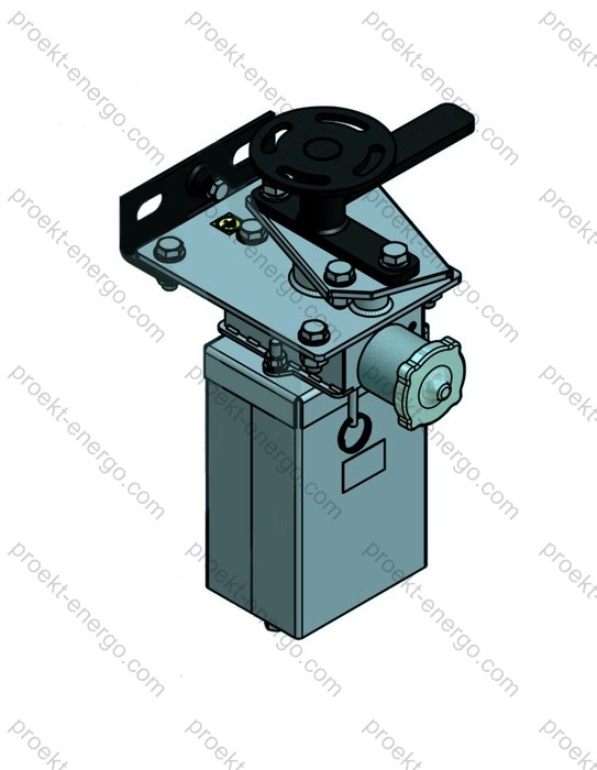
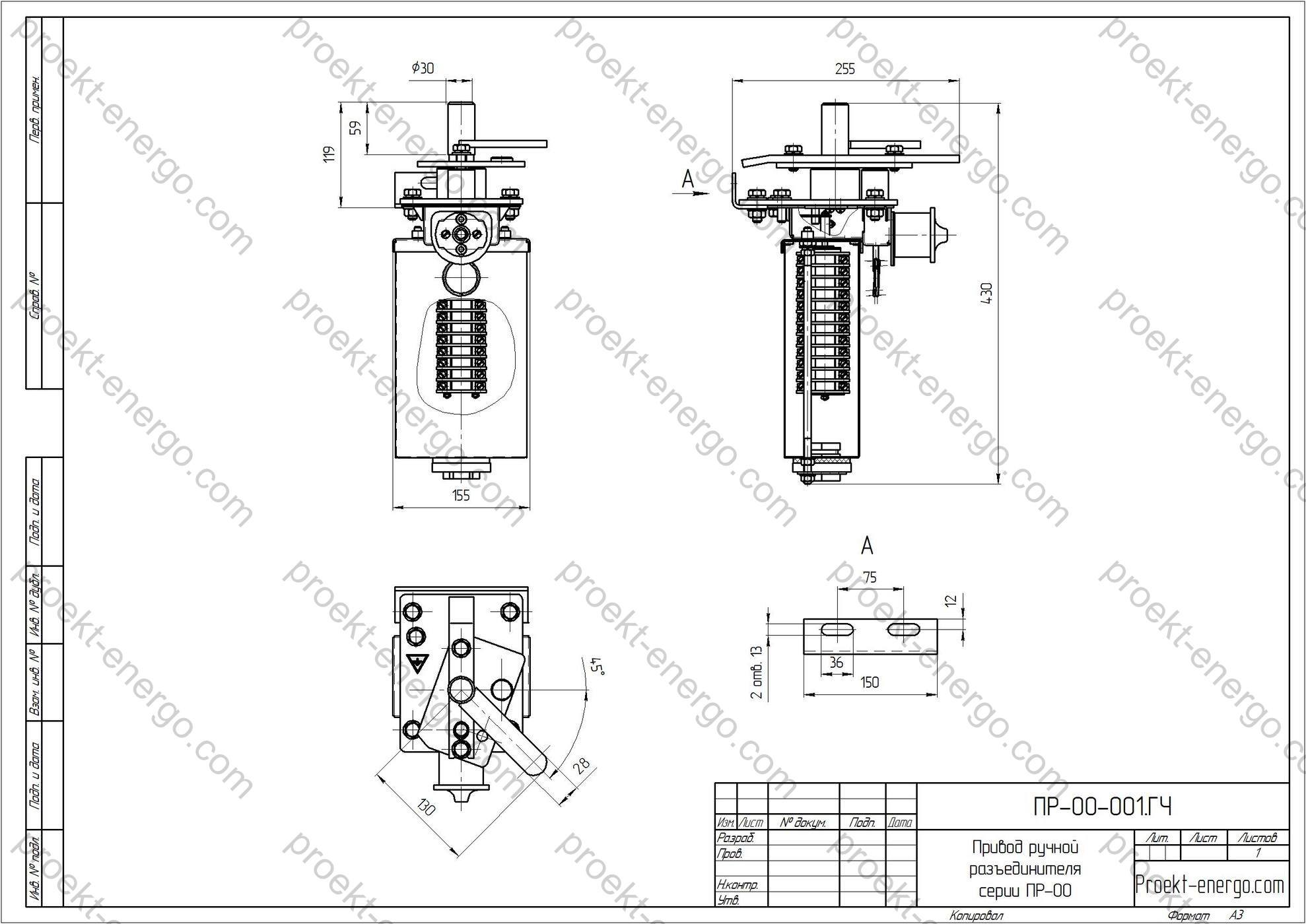
PR-00 mechanisms are intended for manual operation of disconnectors and earthing switches. The mechanisms are manufactured to current industry practice for medium-voltage switchgear and controlgear.
The PR-00 is used to operate the main blades or earthing switches of the latest disconnector series RDZ, RG, RLK, etc., for rated voltages up to 35 kV.
PR-00 is supplied with a single main shaft.
Reliable operation is ensured under the following conditions:
– installation altitude up to 1000 m above sea level;
– upper service ambient temperature +40 °C;
– lower service ambient temperature -60 °C.
The mechanism consists of an enclosure, output shaft, interlock based on the ZB-1M UHL1 electromagnetic lock, a switching mechanism, operating handle, and cable glands.
Access to internal mechanisms (for installation and commissioning) is available after unlocking with a special key and lowering the enclosure cover.
Connection to the disconnector/earthing-switch shaft is made by a clamping hub on the output shaft, allowing adjustment during switching ON/OFF of the disconnector or earthing switch.
The operating handle can be pinned in the horizontal position during an operation; when the operation is completed the handle is set vertically and can be locked with a padlock.

Technical data

Parameter Value
Rated torque at output shaft, N·m 370
Maximum handle force with handle + extension ≤ 1.5 m, N 245
Rated voltage of electromagnetic interlock circuits, V 220
Rotation angle of the main shaft, degrees 90
Rotation angle of earthing-switch shaft, degrees
(for relevant versions)
90
Number of limit-switch contacts KSA (main shaft), pcs 12
Number of limit-switch contacts KSA (earthing-switch shaft), pcs 4
Mass, max., kg:
- PR-00 UHL1
- PR-05 UHL1
- PR-07 UHL1
13
28
20

Purpose and application

The PR-00 manual mechanism is a universal device for driving the main blades of outdoor and indoor medium-voltage disconnectors up to 35 kV, as well as for operating earthing-switch blades within single- and three-pole disconnectors of the RDZ, RG, RLK types and their modifications. The mechanism provides reliable transfer of the apparatus to the end fixed positions “ON”/“OFF”, stable position holding under external influences (wind load, vibration), and both mechanical and electromagnetic interlocking to avoid mal-operations in substation distribution schemes. Typical applications: KRU and KRUN 6–35 kV, outdoor switchyards 10–35 kV, distribution points, industrial and utility interconnection nodes, sectionalizing points, and maintenance isolation on substations.

PR-00 is used in upgrades of existing disconnectors and in new equipment sets. Mechanical compatibility, an adjustable clamping hub on the shaft, unified connection parts, and a wide allowable operating force range make the PR-00 a drop-in replacement for similar manual mechanisms. Manual operation ensures independence from external auxiliary power during switching and increases installation survivability in emergency conditions.

Service conditions

Climatic/environmental category suitable for outdoor use and unheated indoor locations, with a service temperature range from -60 °C to +40 °C. Permitted installation altitude - up to 1000 m a.s.l. The design withstands precipitation and dust typical for outdoor switchyards, provided standard maintenance practices are observed, including periodic checks of gland tightness and seal integrity. In heavy icing regions, protective hoods/covers against direct icing are recommended, along with seasonal servicing of moving joints (cleaning, lubrication, fastener torque check). Operation within KRU/KRUN cubicles is allowed with normal ventilation and in the absence of corrosive gases.

Service-condition parameter Specified value
Environmental classification (indoor/outdoor) EN/IEC 60721-3-3 (weather-protected) / EN/IEC 60721-3-4 (non-weather-protected)
Ambient operating temperature range from -60 °C to +40 °C
Installation altitude up to 1000 m
Installation location Outdoor switchyard 10–35 kV, KRU/KRUN 6–35 kV
System frequency 50/60 Hz (as part of equipment above 1 kV)

Design and layout

The basic layout includes a metal enclosure with a drop-down cover, a main output shaft with a clamping hub, a switching mechanism with fixed end positions, and a hand-operated lever that can be extended to increase the operating arm. The kinematics ensure a 90° rotation of the main shaft with stable end-position latching. Adjustment of transport and working positions is achieved by repositioning the clamping parts on the disconnector shaft and selecting link lengths. The enclosure design allows left/right handle arrangement relative to the shaft axis, simplifying integration of the PR-00 into existing panels and racks.

An electromagnetic interlock based on the ZB-1M UHL1 lock is integrated. The interlock controls access to the mechanism and prevents erroneous ON/OFF operations when supervisory interlocks are active (e.g., from protection relays, auto-reclosing/transfer schemes, inter-equipment interlocks). Unlocking the cover and moving the handle from the “neutral” position are permitted only when an enabling signal is applied to the electromagnet circuit. For commissioning, an emergency key is provided to allow servicing with auxiliary power removed, in line with safety rules.

The output shaft is rated to provide the torque required to move the disconnector blades considering bearing friction and external influences (icing, pollution). The clamping hub ensures precise synchronization of angular positions between apparatus and mechanism, preventing blade skew and incomplete operations. The handle is mechanically latched horizontally during an operation; upon completion it is set vertically and can be padlocked.

Safety and interlocking

The PR-00 interlock system integrates into typical substation interlocking schemes and provides:

  • electromagnetic access interlock (ZB-1M UHL1) powered by 220 V control circuits;
  • mechanical latching of the handle and cover to prevent unauthorized operation;
  • provision for electrical position signalling (installation of KSA limit switches on the shaft) for panel indication and telemetry;
  • process interlocks such as “earthing switch - only with disconnector OFF” (implemented within the site’s kinematic linkages).

The design and materials comply with applicable safety requirements for medium-voltage equipment. Operating procedures should define a clear sequence for personnel: verify absence of voltage, apply earthing, and seal key positions.

Versions and options

The PR-00 is available with different output-shaft orientations and handle placements to facilitate installation and maintenance across various KRU/KRUN and outdoor layouts. Typical options supplied per data sheet, as well as items available as accessories, are listed below.

Option / version Description
Handle orientation Left/right mounting relative to the mechanism enclosure for convenient integration into KRU/KRUN panels and outdoor racks
Handle extension Operation with an increased lever arm up to 1.5 m to reduce operator force (as per the “Technical data” table)
KSA kit Limit switches for “ON/OFF” position indication; wiring prepared for telemetry and alarm circuits
Version for earthing switch* Arrangement of mechanism components for operation with the earthing-switch shaft of the respective disconnector type (to be clarified by project)
ZB-1M key system ZB-1M UHL1 interlock, electromagnetic or magnetic key, emergency release for servicing
Anti-corrosion protection Coatings and seals adapted for outdoor service under EN/IEC 60721 categories

*Applicability and composition for operation with an earthing-switch shaft depend on the specific disconnector model and the panel/rack layout.

Compliance with standards

Design and manufacture of the PR-00 take into account applicable international standards for disconnectors, earthing switches, their operating mechanisms, environmental categories, and safety:

  • EN/IEC 62271-102 - Alternating-current disconnectors and earthing switches (includes requirements for operating devices and auxiliaries);
  • EN/IEC 62271-1 - Common specifications for AC switchgear and controlgear;
  • EN/IEC 62271-200 - AC metal-enclosed switchgear and controlgear (when applied within KRU/KRUN panels);
  • EN/IEC 60721-3-4 / EN/IEC 60721-3-3 - Environmental conditions classification for stationary use at non-weather-protected / weather-protected locations (replacement for legacy climate categories).

Engagement with contractors and partners

We are open to cooperation with mechanical manufacturers, electrical apparatus makers, investors, and integrators. Cooperation can include machining, painting, assembly, and testing of mechanisms and related parts. We provide technology packages, routing sheets, bills of materials, and specifications, along with advice on sourcing components. For disconnector manufacturers, we adapt connection dimensions and kinematics to your apparatus, ensuring compatibility in rotation angles and operating forces.

Documentation offered

Engineering documentation is available for design, manufacturing, and commissioning: manufacturing drawings (DWG/DXF), 3D models (STEP/Parasolid), BOMs, installation and operating manuals, schematic and wiring diagrams for KSA, parts lists, and recommended spares. Documentation is tailored to project requirements and your production capabilities.

Advantages of the PR-00

  • Simple, rigid kinematics - accurate end-position latching and repeatable operations.
  • Manual operation independent of auxiliary power - high reliability in abnormal conditions.
  • Unified connection dimensions and clamping hubs - simplified modernization of existing switchgear.
  • Integrated electromagnetic interlock - reduced operational risk.
  • Adaptable left/right arrangement and enclosure configuration - fewer installation modifications.

Why work with us

– No need to maintain a large engineering team - you get a complete documentation set that can be used by mid-level engineers.
– No pilot units required - our experience allows immediate launch of serial production.
– Working from our documentation, your specialists receive consulting on every nuance of PR-00 manufacturing.

– Flexible cooperation: we help select contractors for machining, painting, supply of standard parts (bearings, seals, fasteners, ZB-1M locks), and commissioning fixtures.
– Reduced production ramp-up times: we provide ready templates of setup sheets and instructions for assembly stations.
– Scalable: documentation supports both small-batch and serial production with standard routings and BOMs.

For additional information on the PR-00 mechanism please contact: inbox@proekt-energo.com

PDF – Download technical information for PR-00 manual mechanism

pdf

Disconnect switch operating mechanism PR-07

PR-07 Manual Disconnector Operating Mechanism

The PR-07 manual operating mechanism is a mechanical drive with a main output shaft and a separate earthing-switch drive shaft, intended for operating the blades of disconnectors and earthing (grounding) switches in distribution installations. The mechanism turns the shafts through a preset angle (typically 90°) and transmits torque to the disconnector/earthing-switch shaft via an adjustable clamp connection. Scope of use - medium-voltage distribution networks of substations and switchgear at industrial, utility and power facilities rated up to 35 kV, as part of disconnector series RDZ, RG, RLK and comparable devices. PR-07 is used to:

  • perform ON/OFF operations of a disconnector’s main blades during operational switching;
  • close earthing blades to ensure safe maintenance and routine work;
  • implement interlocks between apparatus to prevent operator error (for example, blocking earthing-switch closing when the main disconnector is closed);
  • indicate local positions and provide discrete position signals (via KSA auxiliary contact blocks) to a control room annunciation/SCADA system.

PR-07 is applied in outdoor switchyards (AIS) and indoor switchrooms (GIS/MV rooms), for new builds and refurbishments, and as a replacement for obsolete mechanisms during modernization of existing disconnectors. Unified design and adjustment features allow adaptation to a wide range of disconnector sizes and constructions.

Technical data

Rated torque on output shaft, N·m 370
Maximum operating force at the handle with an extension ≤ 1.5 m, N 245
Rated voltage of electromagnetic interlock circuits, V DC 220
Rotation angle of main shaft, degrees 90
Rotation angle of earthing-switch drive shaft, degrees 90
Number of KSA auxiliary contacts - main shaft / earthing-shaft, pcs 12 / 4
Mass, max., kg: PR-00-UHL1 / PR-05-UHL1 / PR-07-UHL1 13 / 28 / 20
Environmental classification / installation category EN/IEC 60721-3-4 (outdoor, unprotected); comparable to UHL1 / category 1
Operating temperature range, °C -60 to +40

Purpose and application

PR-07 mechanisms are intended for manual operation of disconnectors and earthing (grounding) switches. Manufactured to GOST 689-90 (legacy reference) and, for English-language markets, aligned with EN/IEC 62271-102 and EN/IEC 62271-1. The PR-07 operates the contact blades or earthing switches of new-series disconnectors RDZ, RG, RLK, etc., for medium-voltage ratings up to 35 kV. PR-07 is supplied with one main shaft and one earthing-switch drive shaft.

Service conditions

Normal operation is ensured under the following conditions:

  • altitude - up to 1000 m above sea level;
  • upper ambient temperature - +40 °C;
  • lower ambient temperature - -60 °C (for UHL1-type builds);
  • precipitation, wind, dust and rime - within the environmental impacts for outdoor, unprotected locations per EN/IEC 60721-3-4;
  • relative humidity - up to 100% at +25 °C (short-term), without condensation inside the mechanism enclosure;
  • mechanical vibration levels - typical for substation equipment; shocks exceeding MV switchgear service norms are excluded;
  • mounting on vertical or inclined structures with adjustable linkage geometry.

Exterior surfaces feature corrosion-resistant finishes (powder coating / zinc-plated parts depending on configuration) suitable for operation in moderate and cold climates. Design seals and cable glands provide the specified enclosure protection against rain, snow and dust.

Layout and design features

The mechanism consists of a housing, main output shaft, earthing-switch drive shaft, an interlocking device based on ZB-1M UHL1 electromagnetic lock, a cam-type switching mechanism, operating handle, and cable entries for interlocking and signalling circuits. The design emphasizes easy maintenance and high serviceability:

  • Housing - metal, with a hinged drop-down cover. Access during installation and setting is provided after unlocking with a special key and lowering the cover. The interior has guides and mounting points for auxiliary contact blocks, terminal strips and kinematic elements.
  • Output shafts - main and earthing - sized to transmit the rated torque with a 90° rotation. Shaft ends accept keyed/clamp joints for clamps, links and levers. An adjustable clamp on the output shaft enables precise alignment of OPEN/CLOSED positions with the apparatus shaft.
  • Switching mechanism - cam-type, with spring-loaded detents to fix end positions; anti-backdrive elements prevent unintended movement.
  • Auxiliary contact blocks (KSA) - provide discrete position signals for the main shaft (up to 12 contacts) and earthing-shaft (up to 4 contacts). Contact schemes support “dry” contacts or switched voltage for local annunciation/AMR per project.
  • Operating handle - ergonomic, extendable. It is pinned in the horizontal position for operation and parked vertically after operation. In the vertical (parked) position, the handle can be padlocked (operational anti-tamper lockout).
  • Electromagnetic interlock - based on ZB-1M. Without a permissive signal, the plunger remains locked, preventing rotation. When the permissive is applied, the plunger is released by the electromagnet key, allowing the operation.
  • Cable entries - threaded (size per project) for sealed entry of 220 V DC interlock circuits and signalling wiring.

The linkage allows repositioning of levers and arm lengths to match various disconnector and earthing-switch types. Installation is possible on posts, base plates or directly on switchgear steelwork using standard fixing holes.

Safety and interlocking

Personnel safety is ensured by combined electrical and mechanical interlocks:

  • ZB-1M electromagnetic interlock prevents operations unless permissive conditions are met (e.g., adjacent apparatus status). The design includes the lock, KEZ-1M electromagnetic key and KM-1 emergency magnetic key (for release per procedure). Interlock circuit nominal - 220 V DC.
  • Inter-operation interlocks - implemented via the cam mechanism and KSA contacts: earthing-switch closing is blocked when the main disconnector is closed; only the sequence “OPEN disconnector → CLOSE earthing switch” is permitted.
  • Handle mechanical lock - parking in the vertical position with padlock to prevent unauthorized access.
  • Protective earthing - provision for connecting a grounding conductor to the mechanism housing via a designated terminal.

OPEN/CLOSED status to local mimic panels, operator panels or SCADA is transmitted via KSA contacts, simplifying integration into existing control-power schemes.

Versions and options

PR-07 is available in several configurations with options to tailor the mechanism to a specific project:

  • orientation of output shafts and levers (left/right build; top/bottom link rod exit);
  • clamps/couplings to mate with shafts of various diameters and profiles;
  • extended handle/extension bar to reduce operator force (with total handle length ≤ 1.5 m the force does not exceed the specified value);
  • expanded KSA contact sets, including paired contacts for redundant signalling;
  • housing material and coating selection to match environmental corrosion severity;
  • extended hardware and mounting bracket kits;
  • cable glands sized to the required cable diameter/type (glands, sealing bushings);
  • custom terminal and part marking per project schematics.

Standards compliance

The PR-07 design and service characteristics follow the requirements and terminology of the following standards:

  1. GOST 689-90 - “AC disconnectors and earthing switches above 1 kV. General specifications” (legacy reference also covering drives and auxiliaries).
  2. EN/IEC 60721-3-4 - classification of environmental conditions for stationary use at non-weather-protected locations (outdoor), applied here instead of GOST 15150-69 category 1 (UHL1).
  3. EN/IEC 62271-102 - “High-voltage switchgear and controlgear - Part 102: Alternating-current disconnectors and earthing switches”.
  4. EN/IEC 62271-1 - “High-voltage switchgear and controlgear - Part 1: Common specifications”.
  5. EN/IEC 60529 (IP code) - “Degrees of protection provided by enclosures” - for enclosure selection per project.

Available versions and options (for design and ordering)

Parameter Description
Output shaft orientation Left/right build; upper or lower link-rod exit to suit switchgear layout
KSA contact set Base (12 + 4 contacts) or extended set per project scheme
Clamp/coupling type Adjustable clamp for the disconnector shaft (diameter/profile per BOM)
Housing finish Powder coating to RAL / galvanized elements (per environmental category)
Cable entries Threaded glands for the required cable diameter; number of entries per scheme
Accessories Handle extensions, padlocks, mounting brackets, nameplates and pictograms

Engagement with manufacturers and contractors

We welcome cooperation with mechanical engineering plants, substation erection companies and investors interested in localizing and producing PR-07 mechanisms. Based on our documentation, you can:

  • launch serial manufacturing quickly while minimizing development costs;
  • organize cooperation: manufacture sub-assemblies at partner sites with final assembly at your facility;
  • adapt the design to the required disconnector range and regional service conditions;
  • train technologists and assemblers on manufacturing and setting specifics;
  • receive field support at substations (supervisory installation/commissioning by agreement).

Deliverables (for tenders and production)

We provide a complete design package including:

  • pre-tender materials: descriptions, equipment lists, questionnaires, specifications, standards compliance notes;
  • working drawings, kinematic diagrams, assemblies and purchased-parts lists;
  • 3D models and exchange formats: SolidWorks, Parasolid (x_t/x_b), STEP, IGES - for your PLM/CAD integration;
  • 2D drawings: AutoCAD (DWG/DXF) for shop and pre-production;
  • operational documents: user manual, installation and setting instructions, test programs and procedures;
  • personalized nameplates, labels and operational decals per project.

Why work with us

- No need to maintain a large high-skilled engineering staff - you receive a complete documentation set that can be handled by a mid-level engineer.
- No need to build prototypes - our experience enables direct launch of serial batches.
- Working to our documentation, your specialists receive guidance on all nuances of manufacturing and setting the PR-07 manual operating mechanism.

For additional information on the PR-07 mechanism, contact: inbox@proekt-energo.com

PDF - Download PR-07 manual operating mechanism technical information

pdf

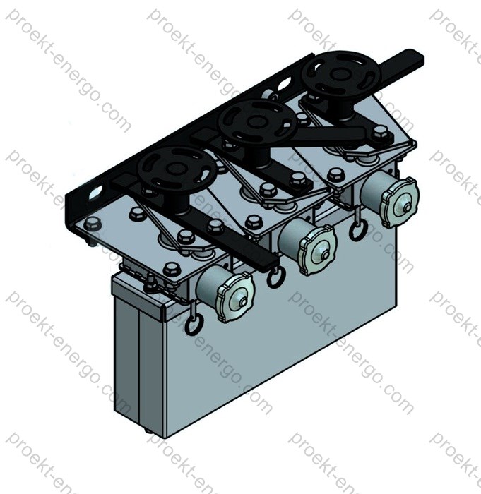
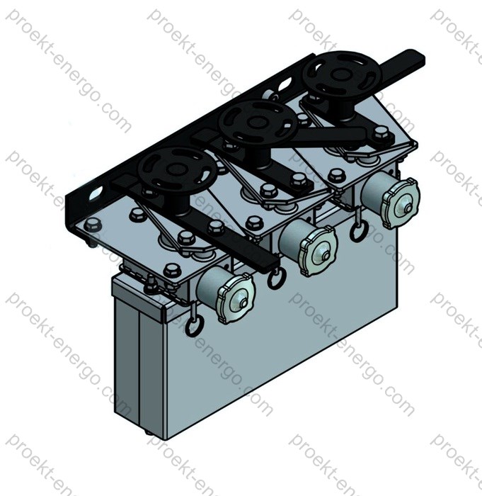
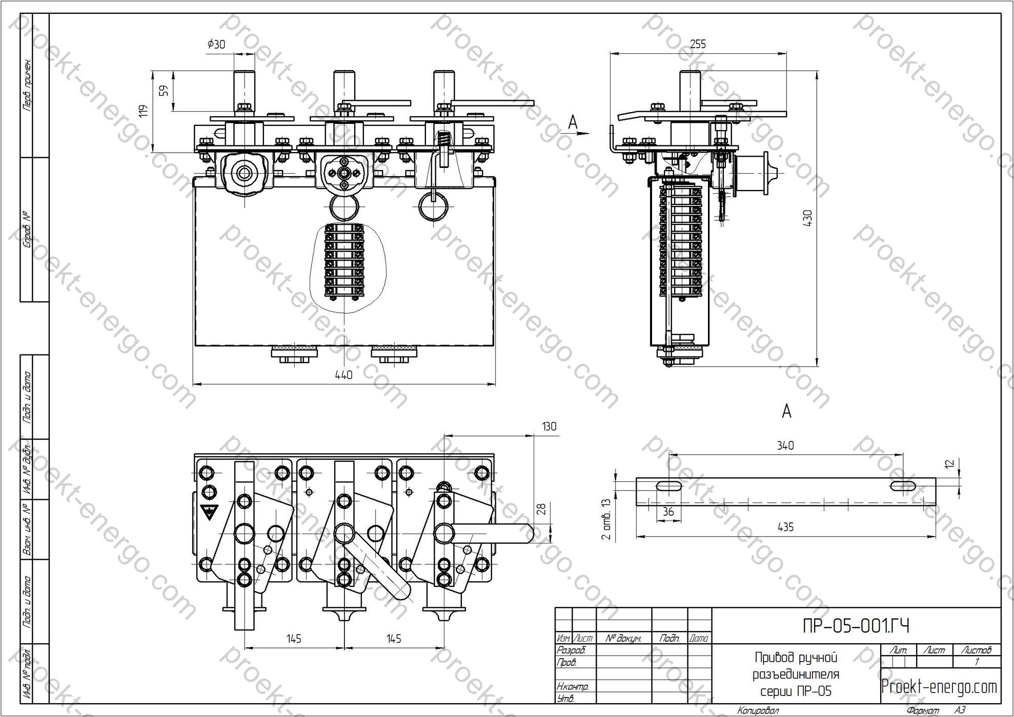
PR-05 Manual Operating Mechanism for Disconnectors

PR-05 mechanisms are intended for manual operation of disconnectors and earthing switches. The mechanisms are manufactured in accordance with GOST 689-90, climatic design UHL, placement category 1 per GOST 15150-69 and GOST 15543-89 (with environmental categories aligned to EN/IEC 60721-3-4 / EN/IEC 60721-3-3).
The PR-05 mechanism is intended to operate the contact blades or earthing switches of the new series of disconnectors RDZ, RG, RLK, etc., for medium-voltage ratings up to 35 kV.
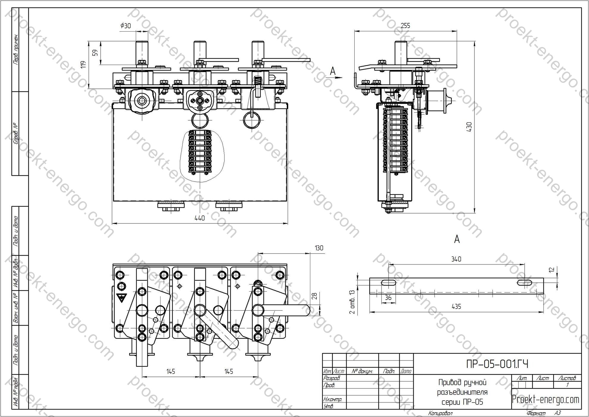
PR-05 is manufactured with one main shaft and two earthing-switch drive shafts.
Normal operation is ensured under the following conditions:
– altitude above sea level not more than 1000 m;
– upper operating ambient temperature +40 °C;
– lower operating ambient temperature -60 °C.
The mechanism consists of a housing, output shaft, an interlocking mechanism based on the electromagnetic key lock ZB-1M UHL1, a switching mechanism, an operating handle and cable glands.
Access to the internal mechanisms (during installation and adjustment) is provided after unlocking with a special key and lowering the cover.
For connection to the disconnector or earthing-switch shaft, a clamping adapter is fixed on the output shaft, allowing adjustment during switching ON/OFF of the disconnector or earthing switch.
The operating handle can be pinned in the horizontal position during operation and, upon completion, set vertically and locked with a padlock.

Technical data

Rated torque at output shaft, N·m 370
Maximum operating force applied to the mechanism with handle + extension up to 1.5 m, N 245
Rated voltage of electromagnetic interlock circuits, V 220
Angle of rotation of the main shaft, deg 90
Angle of rotation of the earthing-switch shaft, deg 90
Number of auxiliary signalling contacts (KSA)
- main shaft
- earthing-switch shaft

12
4
Drive mass, max, kg
PR-00-UHL1
PR-05-UHL1
PR-07-UHL1
13
28
20

Purpose and application

The PR-05 manual operating mechanism is a mechanical drive unit for local operation of three-pole and single-pole switchgear apparatus rated up to 35 kV, including outdoor disconnector series RDZ, RG, RLK and their earthing blades. The mechanism transmits rotary motion to the disconnector’s main shaft with the required torque and precise latching of the end positions “Open/Closed” and “Earthed/Released”, which is essential for operational switching in 6–10–35 kV substation switchgear, distribution points, KRUN, KSO and RP at industrial facilities.

The application scope includes:
- operating the main blades of air disconnectors and earthing-switch drives with an output-shaft rotation angle of 90 deg;
- equipping new-build and refurbished substations with outdoor and indoor switchgear;
- upgrading existing apparatus of domestic and foreign manufacture provided the coupling and connection dimensions of shafts and linkages are coordinated;
- implementing mechanical and electromagnetic interlocks in schemes that must exclude mal-operations (e.g. “closing a disconnector with the circuit breaker not open” or “opening under load”).

PR-05 is aimed for use in distribution networks of industrial and municipal power systems, at small and medium generation facilities, on railway substations, and in the oil & gas and mining sectors where simple, fail-safe, non-energized control of switching devices and reliable position latching are required.

Service conditions

The UHL1 climatic design ensures operation outdoors and in unheated rooms in temperate and cold climates. The operating temperature range corresponds to outdoor equipment requirements: from -60 °C to +40 °C (short-time up to +45 °C). Permissible relative humidity up to 98 % at +25 °C without internal condensation, subject to proper storage and commissioning. Atmospheric pressure corresponds to altitudes up to 1000 m above sea level.

Resistance to vibration and shock corresponds to industrial installation (no permanent impact loads). Operation is permitted at sites with moderately polluted atmosphere (dust, fine sand, salt) provided a protective cover is installed and routine maintenance is carried out. Placement category 1 guarantees resistance to UV and precipitation with correct housing orientation and a weather hood (for outdoor installation). For indoor switchgear (sealed-housing versions), protection against draughts and dripping water is provided.

Requirements for installation and operation:
- mount on a rigid base with accurate alignment of axes “mechanism - transmission linkages - disconnector shaft”;
- eliminate skew and jamming in kinematics; adjust the end-position stops;
- protect cable entries from water ingress; use seals and cable glands per design;
- maintenance interval per manual: fastener check, interlock verification, lubrication of friction pairs (if applicable).

Layout and design solutions

The PR-05 mechanism is built as a standardized cabinet with a drive module. It comprises: a metal housing with anti-corrosion coating; the main output shaft (for disconnector blade operation); two earthing-switch output shafts (for single-pole or grouped blades); a cam/roller-lever switching mechanism; an end-position latching system; an electromagnetic interlock based on the ZB-1M UHL1 lock; an operating handle with optional extension up to 1.5 m; cable glands; and a set of auxiliary signalling contacts (KSA).

Force transfer from the handle to the shafts is implemented via a reduction and lever mechanism that ensures stable torque and high repeatability of the 90 deg rotation. The handle force is limited by ergonomic and operator-safety requirements; optional damping elements and counterweights can be supplied to ease the start and final positioning.

To interface with various disconnector series, interchangeable clamps and adapters are provided on the output shafts, enabling PR-05 to couple with the drive shafts of leading poles of RDZ/RG/RLK and their modifications. The system of adjustable stops and slotted (elliptical) holes on the clamps simplifies fine tuning of pole synchronism and accuracy of end positions on the specific site. The two earthing-switch shafts (independent) allow separate or synchronous operation of earthing blades, including mechanical interlocking of the operation sequence.

The housing provides:
- a hinged drop-down cover with latching for convenient adjustment access;
- a hasp plate for padlocking in the mode “handle vertical, mechanism locked”;
- a mounting panel for terminals, limit switches and cable entries; an optional window for position indication;
- a post/bracket for mounting on steel structures or on a foundation plate.

Position signalling is provided by KSA contact groups (up to 12 contacts for the main shaft and up to 4 for the earthing-switch shaft). The contacts are intended for low-power protection and automation circuits; for auxiliary circuits with higher load, use intermediate relays.

Safety and interlocks

The PR-05 implements a set of measures to prevent mal-operations and ensure personnel safety:

  • Electromagnetic interlock based on the ZB-1M UHL1 lock (with KEZ-1M electromagnetic key and KM-1M emergency magnetic key) prevents handle movement without a permissive signal from adjacent apparatus/protection relays. The electric key enables applying/releasing the interlock only when the scheme logic is satisfied.
  • Mechanical handle latching in the horizontal position during operation and padlock locking in the vertical position - to support LOTO procedures.
  • Adjustable end stops prevent over-rotation of the shaft and consequent mechanical damage to linkages and blades.
  • Position signalling via KSA contacts enables interlocks between circuit breaker - disconnector - earthing switch in switchgear schemes, including blocking closure when an earthing blade is engaged.

All interlock components are arranged for easy service; wiring is performed with screened cable through sealed cable glands. For electrical safety, the housing and all exposed conductive parts have a grounding stud for connection of the PE conductor per project.

Versions and options

The basic PR-05 line can be adapted to a specific disconnector and site conditions. On request:

  • arrangement variants of output shafts (right/left, one or two earthing-switch shafts);
  • handle extensions up to 1.5 m with quick-release coupling;
  • extended KSA set (additional “dry” contacts for telemechanics);
  • housing with enhanced anti-corrosion coating for coastal areas;
  • space heater with thermostat to prevent condensation (version for indoor switchgear);
  • position indicators (mechanical plates/flags) on the shaft and on the front panel;
  • adaptor flanges/clamps for specific RDZ, RG, RLK series and analogues;
  • cable glands for the required cable diameter and type (metal/plastic);
  • inter-apparatus interlock kit (electrical and mechanical) per customer’s scheme.
Version / option Description Purpose
PR-05 basic One main shaft + two earthing-switch shafts, KSA 12/4 Typical configuration for RDZ/RG/RLK
PR-05 with heater Space heater with thermostat Indoor switchgear, condensation/humid rooms
PR-05 marine coating High-resistance anti-corrosion coating Coastal/salt-spray environments
Extended KSA Additional signalling contacts for telemechanics SCADA/DCS integration

Standards compliance

The design and manufacture of PR-05 are oriented to the requirements of the following standards (or their current versions/equivalents):

  • GOST 689-90 “AC disconnectors and earthing switches above 1000 V. General specifications” (as applied to operating mechanisms);
  • GOST 15150-69 “Machines, instruments and other technical products. Versions for different climatic regions” (UHL1 climatic design; environmental categories aligned with EN/IEC 60721-3-4 / EN/IEC 60721-3-3);
  • GOST 15543.1-89 “Electrical products. General requirements for resistance to climatic factors” (reference to IEC 60068 series);
  • IEC 62271-102 “High-voltage switchgear and controlgear - Part 102: AC disconnectors and earthing switches” (applicable to medium-voltage disconnectors and earthing switches);
  • IEC 62271-1 “High-voltage switchgear and controlgear - Common specifications”;
  • ISO 12100 / IEC 60204-1 - general machinery safety and electrical equipment of machines (as applicable).

Engaging partners and manufacturers

We invite manufacturers and investors interested in producing manual mechanisms for medium-voltage disconnectors. We provide a full set of working documentation, manufacturing routings, material and purchased-part specifications, and support in selecting cooperation for machined parts, welded assemblies, protective coatings and assembly. Partners gain access to an up-to-date database of interface dimensions for popular disconnector series and to commissioning/adjustment methods.

System integrators and electrical contractors can include PR-05 in retrofit projects for switchgear and KRUN, receiving from us inquiry sheets, kinematic calculations, adjustment charts and typical interlock schemes using electromagnetic keys.

Documentation and support offered

To accelerate start of production and ensure confident supervision/commissioning, a complete documentation package is provided:

  • general-arrangement and assembly drawings, BOMs and purchased-parts lists;
  • 3D models (STEP/Parasolid), AutoCAD files (DWG), DXF, SolidWorks models;
  • lists of fasteners and interface dimensions, lubrication and adjustment charts;
  • installation and operating manuals, test program & procedures, trial assembly protocols;
  • typical wiring diagrams for KSA and interlock logic (ZB-1M/KEZ-1M);
  • recommendations on materials and coatings for UHL climatic regions.

Scope of supply

The standard scope of supply includes: PR-05 mechanism in the selected version; a set of clamps/adapters for the output shaft; operating handle (with provision for an extension); product passport and operating manual; spare parts per list; installation kit (bolts, washers, cotter pins); terminal markers; optionally - the KEZ-1M electromagnetic key and KM-1M emergency magnetic key.

Why work with us

- No need to maintain highly qualified engineering staff: you receive a documentation package for the product that can be handled by a mid-level engineer.
- No need to build prototypes: our experience allows direct ramp-up of serial production.
- Working to our documentation, your specialists will receive consulting on all nuances of manufacturing the PR-05 manual mechanism.

Cooperation

We are open to cooperation with machine-building plants, machining shops, galvanic and powder-coating facilities, as well as RP/KRUN integrators. We will provide manufacturing routings, control cards, equipment and tooling lists, recommendations on materials and coatings, and we will help to arrange supplies of purchased items (“ZB-1M/KEZ-1M”, KSA, cable glands, fasteners). For investors we will prepare a business plan for setting up production, cost calculations and quality plans.

For additional information on the PR-05 mechanism please contact: inbox@proekt-energo.com

PDF - Download PR-05 manual operating mechanism technical information

pdf

Motorized disconnect switch operating mechanism PD-14

Motorized disconnect switch operating mechanism PD-14

PD-14 type actuator is designed for electromotive operation of main legs and earthing switches of disconnectors with voltage from 35 to 220 kV, rated current up to 2000A, when installed outdoors, as well as from 10 to 110 kV for operation indoors. The drives are manufactured in accordance with GOST 689-90 in the version UHL category 1 according to GOST 15150-69 and GOST 15543-89.
Structurally, the drive is made in the form of blocks containing the gearbox part (BR) and control and signaling units (CU).
The PD-14 actuator consists of the following main parts:
- a cabinet with a rotary panel,
- electric motor with gearbox,
- manual operation blocking mechanism,
- switching device KSAM12.
The PD-14 actuators for operation of the main blades and actuators for operation of the earthing switches have the same design. There is a red stripe on the outside of the earthing switch actuators door.
The cabinet is a prefabricated construction made of stainless steel profiles, additionally sealed with silicone sealant. The cabinet design provides access to control and signaling devices, gearmotor, terminal clamps from three sides: through the door and through removable side covers.
The side covers are fixed to the cabinet by means of nuts. By removing the side covers, the terminal clamps and gearbox gears can be accessed. The inner surface of the door and covers is sealed with silicon-organic rubber, which protects the internal volume of the cabinet from dust and moisture when closed.
The door is attached to the cabinet by means of hinged hinges, which allow the door to open to an angle of no more than 170°.
At the bottom of the cabinet installed sealed cable glands, designed to seal cables with a diameter of 18 to 25 mm. When cables with a smaller diameter are installed, it is necessary to increase the cable diameter by wrapping a PVC insulating tape on it at the cable entry section.

Control units (CU) are designed for remote control of PD-14 actuators during phase-by-phase and three-phase operation of disconnectors. CUs can be installed both indoors and outdoors.
The cabinet is a prefabricated structure made of stainless steel profiles, additionally sealed with silicone sealant. The cabinet design provides access to control and signaling devices, terminal clamps through the door. The inner surface of the door has a seal in the form of silicon organic rubber, which provides protection of the internal volume of the cabinet from dust and rain when closed. The door is attached to the cabinet with hinges that allow the door to open to an angle of up to 170°. The door has a lock that can be locked with a special key. A padlock can be installed in the lock sleeve.

Technical data

Maximum torque on output shaft, Nm 600
Force on the handle at manual operation, N, not more than 60
Output shaft rotation angle, deg. 90; 190
Time of electric motor operation not more than, s 5; 10
Electric motor parameters:
- electric motor power, kW
- rated current, A
- rotational speed, not more than, r/min.

0,25; 0,18
0,63; 2,0
3000
Power of heating devices, W:
- with automatic heating
- with constant heating

200
25
Number of free contacts of auxiliary circuits (NO+NC) 24 (12+12)
Number of handle revolutions during manual operation 22
Disconnector actuator weight, kg: 52 ... 57

We offer you documentation for the manufacture of motorized disconnector actuator PD-14:

- Preliminary technical documentation for participation in tenders for the manufacture of motorized disconnector actuator PD-14. We will prepare for you the necessary information to assess the possibility of manufacturing products in accordance with the requirements of tender documentation and questionnaires.
- Working drawings, 3-D models, and other necessary documentation for the manufacture of motorized disconnector actuator PD-14 at your enterprise. If you do not plan to independently manufacture components and parts of the product, we will help you place their production at third-party enterprises. General assembly of the product and installation will be carried out at your enterprise.
- All documentation, if necessary, is adjusted in accordance with the requirements of the project, as well as in accordance with the technological capabilities of your enterprise.
- If equipment from another manufacturer is installed at the substation, we will prepare for you documentation for the manufacture of similar equipment in addition to the installed one

Advantages of working with us:

- You do not need to employ highly qualified engineers - You receive a set of documentation for the product being manufactured, which can be operated by a semi-skilled engineer.
- You do not need to manufacture prototypes of products - our experience allows us to successfully launch serial batches of products for production.
- Working according to our documentation - your specialists will receive advice on all the nuances of manufacturing of motorized disconnector actuator PD-14.

For additional information on motorized disconnector actuator PD-14, please contact: inbox@proekt-energo.com

... and, as you know, a mistake made during the design of a product results in 10-fold costs during manufacturing, and 100-fold during its operation...

PDF - Download technical information on motorized disconnector actuator PD-14

pdf

  • Technical specifications

    Technical specifications

  • Regulatory and technical documentation

    Regulatory and technical documentation

  • 3-D models

    3-D models

  • Technical specifications

    Technical specifications

  • 3-D models

    3-D models

  • Equipment drawings

    Equipment drawings

  • Operating manual for equipment

    Operating manual for equipment

  • Equipment drawings

    Equipment drawings

  • Regulatory and technical documentation

    Regulatory and technical documentation

  • Operating manual for equipment

    Operating manual for equipment

  • 3-D models

    3-D models

  • Equipment drawings

    Equipment drawings

  • Operating manual for equipment

    Operating manual for equipment

  • Technical specifications

    Technical specifications

  • Regulatory and technical documentation

    Regulatory and technical documentation

Proekt-Energo

FEEDBACK FORM