Outdoor air-insulated switchgear (AIS) blocks for prefabricated transformer substations (KTPB) rated 10(6), 35, 110, 150, 220 kV
The prefabricated modular transformer substation (KTPB) is intended for the reception, conversion, distribution, and transit of three-phase 50 Hz AC power at voltage levels of 10(6), 35, 110, 150, and 220 kV. The KTPB supplies industrial, municipal, and agricultural loads, infrastructure facilities, and is applied on the 35–220 kV side of network substations and, when appropriate, at power plants. The medium-voltage section of the KTPB is based on an outdoor air-insulated switchgear (AIS) assembled from standardized factory-built connection blocks, providing a high degree of factory readiness, shorter construction/erection time, and predictable quality of the finished facility.
AIS blocks for 10(6), 35, 110, 150, and 220 kV are designed for reception and distribution of electric power per the required schemes, switching under load and for maintenance, measurement and metering, as well as limitation of lightning and switching overvoltages. The AIS may include various quantities of both standard blocks and blocks engineered for a specific project and its single-line diagram, climate, wind and icing areas, seismic requirements, and site layout constraints.
Purpose and application
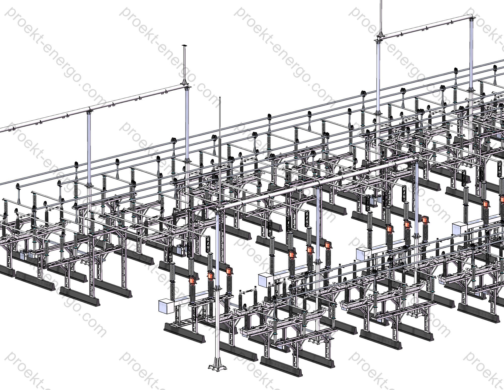
KTPB AIS blocks are used to build the medium-voltage part of substations of all main configurations: terminal, through, tee, node, with one or two main busbar systems, with a bypass bus, with bridge connections and sectionalizing jumpers. The modular concept enables both standard typical schemes and custom solutions with project-specific requirements - from compact 10(6) kV distribution points to 220 kV medium-voltage substation yards with extended functionality.
The typical KTPB configuration for 35–220 kV is formed from the following functional blocks: overhead line (OHL) line-entry blocks with portal or portal-less arrangement; circuit-breaker blocks (incoming, outgoing feeder, sectionalizing and bus-coupler positions); disconnector blocks (line, bus, earthing); current and voltage transformer blocks; surge arrester blocks; cable sealing-end (cable termination) blocks for connection of 35–220 kV cable lines; outdoor station service transformer (SST) block; post-insulator blocks and post-insulators with surge arresters; auxiliary blocks for power-line carrier (PLC) and coupling filters; cable support systems and terminal boxes for secondary circuits.
Operating conditions
AIS blocks are intended for operation in various macro-climatic conditions and installation categories aligned with EN/IEC 60721-3-3 and EN/IEC 60721-3-4, considering wind and icing requirements comparable to common utility codes. Typical service conditions:
- Ambient air temperature: from -45 °C to +40 °C for designs aligned with EN/IEC 60721-3-4; down to -60 °C for extended cold-climate options.
- Altitude: up to 1000 m (base design).
- Reference wind pressure: up to 650–800 N/m² at 10–15 m above grade (depending on the supply region and applicable code base).
- Reference atmospheric icing thickness: 20–34 mm (per project region and applicable standards).
- Atmospheric environment: per EN/IEC 60721 classification; insulation pollution severity: light to heavy (e.g., per IEC 60815) or equivalent categories where applicable.
- Seismic resistance: up to intensity 9 on the MSK-64 scale for equipment installation elevation up to 10 m above grade (subject to the relevant design and project solutions).
The AIS block structures are suitable for regions with elevated wind loads and icing, as well as low-temperature climates, while ensuring the required electrodynamic and thermal withstand of live parts, stability of supporting steelwork, and prescribed clearances to ground, fences, and adjacent live parts. Where needed, noise-mitigation solutions can be applied (for urban areas), and layouts with reduced visual and land-use footprint are available.
Layout and design solutions
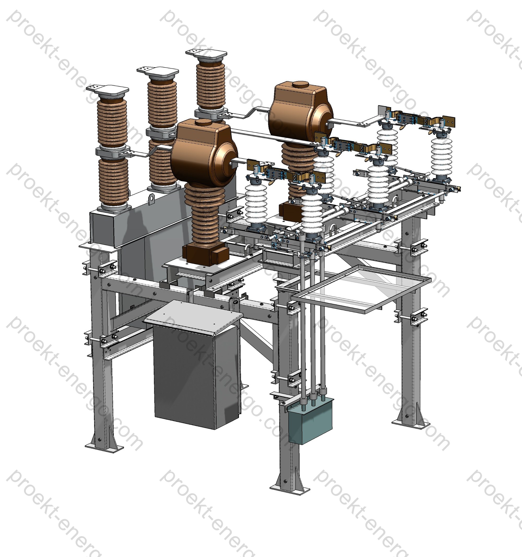
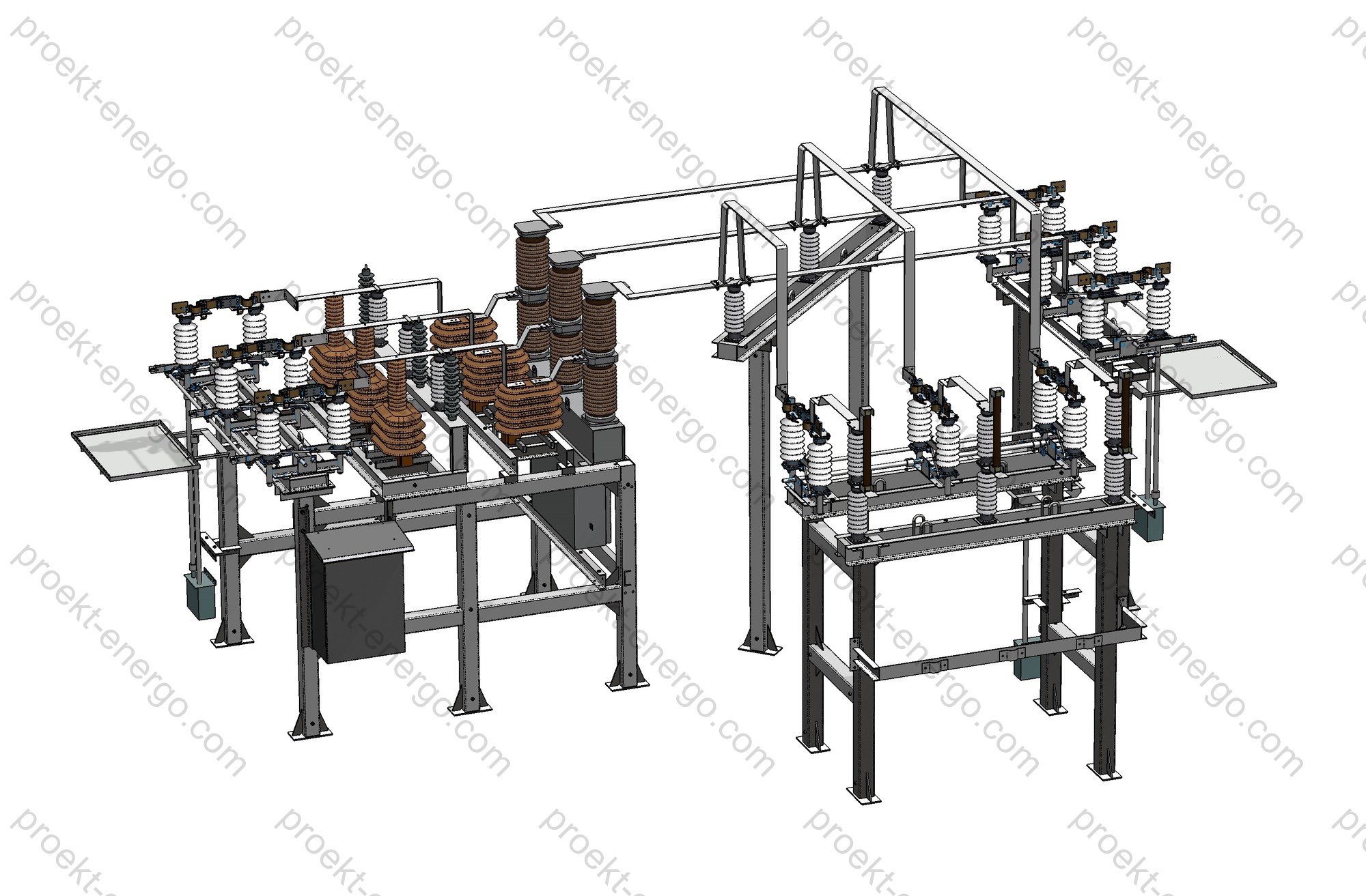
AIS 10(6)–220 kV is built from standardized, transportable factory-assembled blocks - steel support frames fitted with circuit breakers, disconnectors, instrument transformers, surge arresters, buswork elements, operating mechanisms, and secondary wiring cabinets. Each block is a complete functional unit minimizing on-site works: installation on sleepers/pile foundations/grade beams, connection of rigid/flexible bus, and hookup of secondary circuits.
Depending on the voltage class and the selected single-line diagram, the following basic block types are used:
- Line-entry block (OHL reception): connects an overhead line to the AIS. Portal and portal-less entries (for 35–220 kV) are available, with suspension strings, downlead fixtures, and standardized electrical clearances. In the portal-less option, downleads connect directly to the conductors of the first OHL span and to the block’s post insulators, simplifying the node, reducing steelwork and cost.
- Circuit-breaker block: performs planned and fault switching under load (incoming, outgoing feeder, sectionalizing, bus-coupler, bypass), provides selective fault clearing, and integrates current transformers (built-in or stand-alone) and protection & control (P&C) devices.
- Disconnector block: three-pole line/bus/earthing disconnector provides a visible isolating gap, no-load switching, and earthing of de-energized sections via earthing blades. Operated by manual or motor drives with the option of remote control from pedestal-mounted cabinets.
- Voltage transformer (VT/PT) block: for measurement, metering, and voltage-based protections; single-phase or three-phase designs (dry/oil/SF6/capacitive/CVT/anti-ferroresonance - depending on voltage and task). May be installed on the line side, at the outer bus span, or within a bay.
- Current transformer (CT) block: provides measurement and feeds P&C/metering current circuits where CTs built into breakers or other blocks are not sufficient; used in line, transformer, and jumper circuits.
- Surge arrester (MOV) block: limits lightning and switching overvoltages; may be placed on the line/bus side or within combined blocks (e.g., post insulators with arresters).
- Cable termination (sealing-end) block: for connecting 35–220 kV cable lines; may be supplemented by a disconnector, zero-sequence current transformer (ZCT), surge arrester, and a secondary wiring cabinet.
- Outdoor station service transformer (SST) block: feeds the substation auxiliaries (typically up to 100 kVA in the base configuration) with fuses and switching devices.
- Post-insulator / post-insulator with arrester blocks: support buswork and mechanically fix live parts, providing the required insulation and mechanical strength; porcelain/polymer/rod/suspension types can be selected per client request and climate.
Rigid buswork is typically aluminum alloy tube in one or two tiers; sliding and articulated supports are used to compensate thermal expansion. Flexible bus (aluminum or ACSR conductor) is used for short jumpers, downleads, and connections to transformer (autotransformer) and apparatus terminals. Secondary circuits within the blocks are factory-wired to terminal boxes; inter-block connections are routed on cable trays (on-grade or overhead) at elevations ensuring safe and convenient operation.
Remote-control cabinets for motor drives of disconnectors are mounted on separate pedestals (usually up to two cabinets per pedestal). The design documentation defines pedestal locations, embedded parts/sleepers or piles, as well as control and signaling cables. This layout improves maintainability, ensures clear visibility of the operated device, and meets electrical safety requirements.
Block types for AIS 35–220 kV (indicative list)
- Line-entry block (OHL reception) - portal/portal-less;
- Circuit-breaker block - incoming, outgoing feeder, sectionalizing, bus-coupler, bypass;
- Disconnector block - line/bus/earthing;
- VT/PT block - single-phase/three-phase, anti-ferroresonance, capacitive (CVT), cascade;
- CT block - line, transformer, additional (for separate metering/P&C schemes);
- Surge arrester block and post-insulator-with-arrester block;
- Cable termination block (35–220 kV CL) with/without disconnector and ZCT;
- SST block (outdoor installation);
- Auxiliary PLC/coupling-filter blocks, terminal and relay cabinets.
Table. Most demanded AIS blocks by function
| Function | Block type | Brief purpose | Notes on scope of supply |
|---|---|---|---|
| Power intake/export | Line-entry block (OHL) | Connection of 35–220 kV OHL to AIS | Portal or portal-less entry; suspension strings; surge arresters as justified |
| Load switching | Circuit-breaker block (incoming/OF/sectionalizing/bus-coupler) | Opening/closing feeders and bus sectionalizing | Selection of vacuum/SF6 breaker by voltage class and currents |
| Operational isolation | Disconnector block (line/bus/earthing) | Visible isolating gap; earthing of de-energized sections | Manual/motor drive; auxiliary contacts; remote-control cabinet |
| Voltage measurement | Voltage transformer block | Measurement, metering, and voltage-based protections | Dry/oil/SF6/capacitive (per task and kV class) |
| Current measurement | Current transformer block | Metering & P&C when built-in CTs are absent/insufficient | Line, transformer, and additional CTs |
| Overvoltage limitation | Surge arrester block / post-insulator with arrester | Protection against lightning and switching overvoltages | Arrester operation counter upon request |
| Cable line connection | Cable termination block | Connection of 35–220 kV cable lines to AIS | Optional disconnector, ZCT, surge arrester |
| Station auxiliaries supply | SST block (outdoor) | Powering substation auxiliaries | Disconnector, fuses, transformer up to 100 kVA (typical) |
Safety
Personnel safety and equipment reliability are embedded in the AIS block architecture. A visible break of the main circuit is provided with the possibility of earthing on both sides of the break; operating devices of disconnectors and circuit breakers are located at safe heights and in accessible areas. Design clearances and distances to ground, fences, and adjacent live parts follow common utility practice and applicable standards. Modern switching devices with high electrodynamic and thermal withstand, high-quality polymer and porcelain insulators, and proven routing of secondary cables are applied to prevent inadvertent contact with live parts.
When motor drives are selected for disconnectors, remote cabinets on separate pedestals are provided with position indication of blades and earthing switches and with auxiliary contacts for integration into protection and SCADA schemes. This enables safe operation away from live parts and visual status control.
Typical configurations (examples)
Below are common main-connection schemes implemented with a set of standardized AIS blocks. The specific scope and composition of blocks are defined by the project and data sheets considering currents, overvoltage levels, environmental conditions, and supply reliability requirements.
| Scheme | Brief description | Typical set of blocks |
|---|---|---|
| 35 kV: single bus system with sectionalizing breaker | Compact AIS-35 kV configuration for distribution nodes | Line blocks (OHL/CL entries), CB blocks (incoming/outgoing), sectionalizing CB block, VT/CT blocks, surge arrester blocks, trays and cabinets |
| 110 kV: bridge with breakers in line circuits | Through node with a maintenance jumper option | Two “line–breaker” blocks, jumper and VT/CT blocks, surge arrester block, OHL entry (portal/portal-less) |
| 110 kV: one main and one bypass bus system | Enhanced reliability and maintenance without de-energizing feeders | Incoming/outgoing CB blocks, sectionalizing/bus-coupler CB blocks, VT/CT blocks, bus disconnectors |
| 150/220 kV: ring (breaker-and-a-half / quadrilateral) | High survivability, wide switching and maintenance capabilities | “Line–breaker” blocks, CT/VT blocks, surge arrester blocks, post insulators, cable structures |
| 220 kV: two main bus systems and a bypass bus | Maximum reliability and operational flexibility | Incomings, outgoing feeders, sectionalizing and bus-coupler breakers, bus disconnectors, VT/CT, surge arresters, OHL entry blocks |
Compliance with standards
AIS blocks and applied equipment comply with the requirements of widely used international standards, including:
- EN/IEC 60721-3-3 and EN/IEC 60721-3-4 (environmental conditions for stationary use at weather-protected and non-weather-protected locations); IEC 60068 series for environmental tests as applicable;
- IEC 60815 (selection and dimensioning of high-voltage insulators under polluted conditions) for insulation pollution severity;
- IEC 62271 series (high-voltage switchgear and controlgear), incl. 62271-1 (common specifications), 62271-100 (AC circuit-breakers), 62271-102 (disconnectors and earthing switches);
- IEC 61869 series (instrument transformers - CTs/VTs/CVTs); IEC 60099-4 (metal-oxide surge arresters);
- IEC/EN 61936-1 (power installations exceeding 1 kV AC) and applicable national codes for electrical clearances and substation design; wind/icing per the project’s adopted civil/structural codes;
- Seismic resistance up to MSK-64 intensity 9 where specified by the project;
- Manufacturer’s technical specifications for KTPB/AIS and component devices.
Engagement of contractors, equipment manufacturers, and investors
We are open to cooperation on manufacturing AIS blocks and components: steel structures, cabinets, cable trays, secondary harnesses, buswork elements, as well as supply of switching devices, instrument transformers, surge arresters, and other components. Cooperation may include licensed transfer of working documentation, author supervision during manufacturing, supervisory erection and commissioning support, and joint localization of production to suit the target region. For investors and manufacturing sites we offer a ready documentation package, process support, and personnel training for serial production launch.
Documentation offered
A complete documentation set is provided for manufacturing and supply of KTPB AIS blocks rated 10(6), 35, 110, 150, 220 kV:
- Pre-tender technical documents (descriptions, specifications, data sheets, technical decision approval sheets).
- Detailed design documentation: general arrangement drawings, assembly drawings of blocks and units, BOMs for purchased items and materials, main and auxiliary circuit diagrams, cable schedules.
- Digital 3D models and files for project integration: AutoCAD (DWG/DXF), SolidWorks (SLDPRT/SLDASM), Parasolid (X_T/X_B), STEP/IGES, plus a PDF package for authorities.
- Instructions for transportation, storage, installation, commissioning, and operation; typical test programs and methods.
- Supply lists and data sheets for execution variants (climate, seismic, pollution level, portal/portal-less entry, apparatus types).
Benefits of working with us
- Reduced design and construction time due to the high factory-build content of the blocks.
- No need to maintain a large staff of narrow specialists: the complete working documentation enables fabrication by an in-house engineering team with consultative support from our specialists.
- Serial launches without pilot prototypes - design for manufacturability and a proven component base lower risks and implementation costs.
- Support at all stages: pre-design studies, equipment selection, manufacturing, supervisory erection, commissioning, warranty and post-warranty service.
For additional information on KTPB AIS blocks rated 10, 35, 110, 150, 220 kV please contact: inbox@proekt-energo.com
PDF - Download technical information on KTPB AIS blocks rated 10, 35, 110, 150, 220 kV