Working design documentation for the manufacture of electrical equipment for substations. 3D models. Drawings. Regulatory documentation.

Outdoor switchgear K-3 (K-III)

K-3 (K-III) Outdoor Metal-Enclosed Medium-Voltage Switchgear

The KRUN K-3 (K-III) outdoor metal-enclosed medium-voltage switchgear is intended for the reception and distribution of three-phase AC power at 50 Hz with rated voltages of 6–10 kV. It is applied in auxiliary power systems of power plants, at substation switchyards of utility grids and industrial facilities, for agricultural power supply, as well as in the oil & gas production sector.
KRUN K-3 (K-III) is assembled from individual cubicles. Enclosures are welded from bent sheet steel. Each cubicle is divided by solid metal partitions into compartments: medium-voltage, control, and busbar. Adjacent cubicles have openings for busbar connections, bolting holes for forming a single block, and openings for routing control cables. Depending on function, cubicles are configured as follows:
- VCB cubicle - vacuum circuit-breaker feeder (cable / busbar / overhead line entry);
- SST cubicle - station service transformer;
- BS CB - bus-section circuit-breaker cubicle;
- VT cubicle - voltage transformer;
- BS DS - bus-section disconnector cubicle.
The quantity and types of cubicles are selected according to the project.
A vacuum circuit-breaker cubicle can include a line disconnector, a busbar disconnector, a vacuum circuit breaker, current transformers, and-if required-surge arresters and a core-balance (zero-sequence) CT.
A voltage-transformer cubicle includes a VT with a busbar disconnector and fuses; it also accommodates busbar earthing switches. Surge arresters may be installed on the main busbars.
A station service transformer cubicle houses the power transformer (specified in the data sheet, typically 25 or 40 kVA), together with a busbar disconnector and fuses. Depending on the single-line diagram, an overhead line entry of the incoming breaker can be routed into the SST cubicle.

Purpose and Application

KRUN K-3 (K-III) is designed for building reliable 6–10 kV medium-voltage networks at outdoor substations and as part of compact transformer substations. It provides line in/out, bus/feeder sectioning, metering, measurement, protection, and automation for networks with isolated neutral or with neutral earthed through an arc-suppression reactor. Typical applications include:

  • Auxiliary power switchgear of power plants; outdoor switchyards (35–220 kV) with 6–10 kV MV sections.
  • Industrial sites: mining & processing, metallurgical and chemical plants, refineries, oil & gas production pads, transport and port infrastructure.
  • Agricultural consumers, farms, grain elevators, and distribution points on long 6–10 kV OH/UG feeders, including feeder sectioning and automatic transfer/reclosing.
  • Temporary and permanent power for construction bases, quarry complexes, and fields with mobile logistics.

Functionally, KRUN K-3 (K-III) receives power from power transformers and distributes it to outgoing feeders, sections buses/feeders, connects measuring transformers and station-service transformers, and integrates with AMR/AMI systems and telecontrol subsystems. The enclosure design and built-in equipment allow both compact distribution points and extended bus sections with various connection schemes-from simple incomers to complex nodes with bus-section circuit breakers, bypass links, and bus bridges.
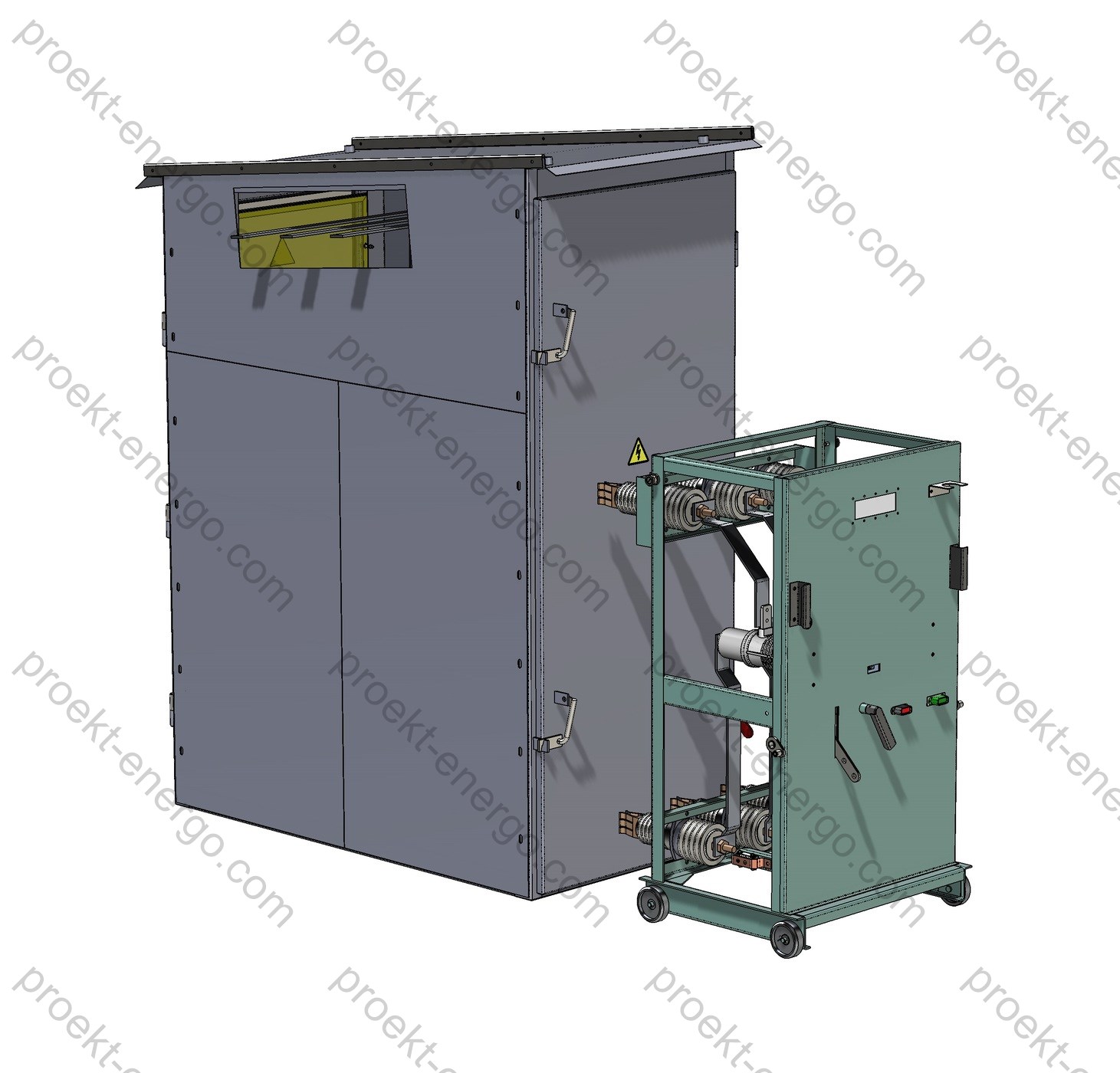
Technical Data

Rated voltage, kV 6; 10
Maximum operating voltage, kV 7.2; 12
Rated current (main circuits), A 630; 1000; 1600
Rated busbar current, A 630; 1000; 1600
Thermal withstand current 3 s, kA 20; 25; 31.5
Dynamic (peak) withstand current ~1 s, kA 51
Environmental category (EN/IEC 60721-3-4) EN/IEC 60721-3-4 (outdoor)
Ingress protection (IEC 60529) splash-proof IР34
Service corridor none (front access)
Type of line MV terminations cable, overhead
Insulation level (IEC 62271-1/-200) standard insulation
Withdrawable elements none (fixed-mounted)
Overall dimensions, mm
- width
- depth
- height

1000
1870
2500

Service Conditions

Cubicles are intended for outdoor installation and continuous duty under the following normalized environmental factors:

  • Environmental category - EN/IEC 60721-3-4 (outdoor). The K-3 series is engineered for moderate climates with exposure to precipitation, dust, and solar radiation. The enclosure includes drip edges and splash protection (IP34) to prevent ingress of rain and melt water.
  • Installation altitude - up to 1000 m above sea level without derating; higher-altitude use may require adjusted insulation levels and currents.
  • Location category - outdoor; vertical operating position; non-hazardous atmosphere, not saturated with conductive dust or aggressive vapors; no internal condensation provided ventilation and heating requirements are observed.
  • Wind and snow loads are considered in foundation/support design and when selecting optional overhead line entries; in areas with deep snow cover, installation on an elevated platform is permissible (plinth/skid height per project).
  • Options for seismic reinforcement, enhanced anticorrosion coating, “North” package (thermostated heaters, insulated cable entries, moisture protection of the relay compartment), and “Dust/Desert” package (additional filter inserts, mesh screens on ventilation) - as per data sheet.

For correct operation of protection and switching devices, maintain the specified microclimate in the control/relay compartment: dry, heated volume without condensation. Anti-condensation heaters with thermostat are used (installed in breaker and P&C compartments), and cable glands with seals prevent air/moisture ingress.

Layout and Design

KRUN K-3 (K-III) is a modular assembly in a welded metal enclosure with functional segregation by internal partitions. A typical cubicle comprises the following isolated compartments:

  • MV circuit-breaker compartment - vacuum circuit breaker (6/10 kV class), current transformers, optional core-balance CT (ring CT around cables), interlocks, position sensors, and arc-flash detection (project-specific). Compartment lighting and heating are provided; removable panels support inspection of contacts and secondary wiring.
  • Disconnector and busbar compartment - line/busbar disconnectors with earthing switches, support/bushing insulators, and busbars. Behind the door there is a protective mesh or dielectric screen with viewing windows for visual position check. Mechanical interlocks prevent incorrect operations between work and earthing blades.
  • Incoming/feeder terminations - termination of underground cables or overhead line entry with cross-arm and bushings. Surge arresters may be installed at the incomer/feeder; line CTs and capacitive voltage indicators are available for voltage-absence verification prior to earthing.
  • Protection & control (P&C) compartment - microprocessor relays (O/C, TOC, earth-fault, under/over-voltage, autoreclose, ATS as required), RTU/PLC for telecontrol, alarm/measurement devices, AMR/AMI meters (accuracy classes 0.5S–1), DC supplies, and terminal blocks. The fascia provides local breaker controls and PR-10 disconnector drives with status indication and key interlocking.

All compartments are sealed volumes separated by solid metallic/insulating partitions, improving fault containment and preventing transfer of arc products between compartments. Air clearances and creepage distances meet the 6/10/12 kV insulation level. Busbars are copper/aluminum with bolted joints; they are air-insulated for easier inspection and maintenance. Provisions are made for inter-cubicle bus joints, bolted tie bars, and secondary cable trays to simplify installation.

The enclosure provides splash-proof protection to IP34: drip edges exclude direct runoff to door openings; ventilation channels use labyrinth paths and mesh filters. Doors have multi-point locks and provisions for padlocks. A comprehensive interlock system ensures safe access: with the breaker and/or disconnectors closed, access to MV compartments is prevented; earthing switches cannot be closed with work blades closed. A grounding point is provided at the base for connection to the external earthing grid; all metal parts are bonded to the enclosure with flexible braids/star washers for reliable electrical contact.

Connection options support both cable and overhead line in/out. Cable terminations use sealed glands and support insulators; overhead line entries use bushings, cross-arms, and lightning protection as per project. The design allows bus-section nodes with bus links and bus-section devices (breaker/disconnector), as well as placement of a station service transformer (25–40 kVA or as specified) in a dedicated cubicle with fuses and a busbar disconnector.

Safety and Interlocking

  • Blocking of disconnector operations with the MV circuit breaker closed (mechanical/electrical interlocks per scheme).
  • Blocking between working and earthing blades in both directions; intermediate positions excluded by drive latching and limit switches.
  • Access to MV compartments is interlocked with device status; doors open only after de-energizing, opening disconnectors, and closing earthing switches.
  • Voltage-absence verification (indicators/capacitive sensors) before earthing; application of portable earthing to designated points.
  • Arc-flash protection of breaker/bus compartments (optional): light sensors + high-speed tripping; pressure relief flaps for overpressure venting.

Configurations and Options

  • Cubicles: incomers (UG cable/OHL), outgoing feeders, bus-section (breaker/disconnector), busbar incomers/links, VT, SST, combined.
  • Switchgear devices: vacuum circuit breakers 6/10 kV (breaking capacity up to 20–31.5 kA), disconnectors with PR-10 drives, earthing switches.
  • Instrument transformers: CTs with primary currents 50–1500 A, single-/three-phase VTs.
  • Surge arresters on busbars and on incomers/feeders; voltage indicators, viewing windows.
  • Protection functions: O/C, TOC, earth-fault, under/over-voltage, autoreclose (AR), automatic transfer (ATS); integration with SCADA and telecontrol (Modbus/IEC 60870-5-104/IEC 61850).
  • Environmental packages: “North”, “Dust/Desert”, “Marine” (anticorrosion, sealing, heating), anti-vandal versions, enhanced seismic performance - on request.

Typical Configurations

  • Incoming cubicle with vacuum circuit breaker, busbar and line disconnectors, CTs, and surge arresters. Cable/OHL entry - per project.
  • Outgoing feeder (cable) with breaker, CTs, core-balance CT (for selective earth-fault), feeder surge arresters, local/remote control.
  • Bus-section cubicle with circuit breaker (BS CB) for splitting busbars, AR/ATS per relay logic; or bus-section disconnector (BS DS) for maintenance switching.
  • VT cubicle (measurement/metering), SST cubicle (25–40 kVA and above, station service supply), busbar incomers/links for multi-row schemes.

Standards Compliance

  • EN/IEC 60721-3-4 - environmental categories for outdoor stationary use (replaces GOST 15150 U1).
  • IEC 60529 - degrees of protection (IP); enclosure rating IP34.
  • IEC 62271-1 / IEC 62271-200 - AC metal-enclosed MV switchgear and controlgear; insulation/dielectric tests and general requirements.
  • IEC 62271-100 / IEC 62271-102 - circuit breakers; disconnectors and earthing switches (as applicable).
  • IEC 60068-2 series - environmental/mechanical tests (vibration/shock, etc.).
  • Commissioning and acceptance testing per applicable IEC/EN standards, FAT/SAT and customer specifications.

Partnering and OEM Cooperation

We invite manufacturing sites and investors to arrange KRUN K-3 (K-III) production under our documentation. We are open to OEM components from leading brands and local suppliers (cable terminations, surge arresters, protection relays). Partners receive guidance on manufacturability, component selection, shop adaptation, and training for assemblers and commissioning personnel.

Documentation Deliverables

We provide a complete design & manufacturing package: BOMs, assembly drawings, primary and secondary schematics, layout drawings, cable lists and secondary wiring lists. Available formats: 2D (DWG/DXF), 3D (SolidWorks/Parasolid), purchased-parts lists, data sheets, transport/storage/installation/operation manuals. On request - export specifications, recommended spares, FAT/SAT templates, and test sheets aligned with IEC requirements. For sites with existing third-party equipment, we can perform reverse engineering and supply compatible cubicles.

Why work with us:

- No need to staff highly specialized engineering teams - you receive a complete documentation set for manufacturing, suitable for engineers of average qualification. 
- No need to build pilot prototypes - our experience allows direct launch of serial production.
- Working to our documentation - your team receives guidance on all manufacturing nuances of KRUN K-3 (K-III).

For additional information on KRUN K-3 (K-III), contact: inbox@proekt-energo.com

... and, as is well known, an error made at the design stage turns into 10× cost in manufacturing and 100× in operation...

PDF - Download KRUN K-3 (K-III) technical information.

pdf

Outdoor switchgear K-37

K-37 Outdoor Metal-Enclosed Switchgear

The KRUN (outdoor metal-enclosed switchgear) series K-37 is a modular solution for the reception and distribution of three-phase AC power at 50 Hz with rated voltages of 6 and 10 kV. These units are used in power plant auxiliary switchboards, step-down and distribution substations, and across industrial, oil & gas, mining, transport and agro-industrial facilities, as well as within packaged transformer substations and skid/block substations for a wide range of climatic conditions. The K-37 is engineered for long-term outdoor service, simplifying installation, improving maintainability, and enhancing personnel safety by means of comprehensive mechanical interlocking, internal arc-fault containment measures, and a convenient compartment layout.

Purpose and applications

KRUN K-37 is intended for 6/10 kV power reception and distribution; busbar sectionalizing and bus tie/backup; (3) connection of cable and overhead feeders; (4) feeding of station service transformers (SST) and MV measuring/metering circuits at 6–10 kV; (5) housing of protection, automation and telecontrol equipment. A typical K-37 cubicle can perform the functions of an incoming or feeder panel, bus tie circuit-breaker, sectionalizing disconnector, VT (voltage transformer) panel, SST panel, or a combined feeder. This flexibility allows standardized modules to be configured into switchboards of different ratings and schemes-from compact auxiliary boards to fully sectionalized distribution nodes at 35/6–10 and 110/6–10 kV substations.

K-37 cubicles are divided into independent compartments (incoming/feeder connections, busbar compartment, drawout unit compartment, relay cabinet), improving fault localization, reducing the risk of damage propagation, and easing maintenance. Each compartment has its own pressure-relief channels (relief flaps and rupturable panels) and automatic shutter mechanisms that block access to live parts when the truck is withdrawn.

Technical data

Rated voltage, kV 6; 10
Highest system voltage, kV 7.2; 12
Rated current of main circuits, A 630; 1250; 1600; 2000; 2500; 3150
Rated busbar current, A 1250; 1600; 2000; 3150
Short-time (thermal) withstand current, 3 s, kA 20; 25; 31.5
Peak (dynamic) withstand current, kA 51
Environmental category (EN/IEC 60721-3-4) Outdoor; temperate (no thermal insulation) / cold-climate (with thermal insulation)
Thermal insulation in KRUN - temperate option: without thermal insulation
- cold-climate option: with thermal insulation
Walk-in service corridor Provided
Type of line MV connections Cable, overhead
Insulation level per EN/IEC 62271-1 Standard insulation level
Drawout (withdrawable) elements With drawout element
Overall dimensions, mm
- width
- depth
- height

3500
900; 1350
3300

Service conditions

KRUN K-37 is manufactured for outdoor use with a walk-in control corridor and two-sided access, in environmental categories per EN/IEC 60721-3-4, with standard or enhanced external insulation. For the temperate option a splash-proof enclosure is provided (typical IP34 per EN/IEC 60529); for the cold-climate option-dust- and water-protected, up to IP54, with insulated panels to ensure reliable starting and operation at low temperatures and in dew formation conditions. Permissible installation altitude-up to 1000 m (higher altitudes by agreement with the manufacturer with appropriate insulation and cooling adjustments). The standard design allows operation at ambient temperatures up to +40 °C and down to -45 °C (temperate) and -60 °C (cold-climate), under site wind loads and with monthly mean relative humidity up to 90%. To mitigate condensation/icing, compartments are equipped with space heaters with automatic temperature/humidity control; cable and secondary wiring are routed in metallic trays/conduits for shielding and mechanical protection.

Design features and materials (dew-resistant insulators, gaskets, canopies, insulated corridor panels) are adapted for regions with high insolation, wind and snow loads, icing and dust. External canopies, interior/exterior lighting (typically 220 V), ventilation louvers and service hatches are provided for safe inspection with adjacent compartments de-energized.

Layout and construction

K-37 is built as a block of one, two or three side-by-side MV cubicles on a rigid common base frame, integrated by a walk-in control corridor. Multiple blocks can be coupled in a straight lineup by busbars or via a sectionalizing device. Each cubicle’s fixed frame carries through-type insulators with fixed contacts, current transformers, an earthing switch, and bus/feeder bars; the drawout truck accommodates the medium-voltage circuit-breaker (or isolating contacts/fuses), VTs/SST per the selected configuration. For overhead terminations, roof brackets and bushings are provided; for cable terminations-entry clamps and cable brackets. The default bus system is single bus, with bare copper bars; phasing and color coding follow IEC practice and the site convention. Line feeder terminations are accessible from the rear; doors with guarding allow visual checks without de-energizing the bus.

The relay cabinet is located above the drawout compartment; its door carries local controls, indication and metering. Inside are protection, automation, metering and communications devices (including microprocessor IEDs per IEC/ANSI function codes, AR-automatic reclosing, ATS-automatic transfer for auxiliaries, UFLS-under-frequency load shedding, undervoltage protection, etc.). The connection between the truck and the relay cabinet is via plug-in connectors with flexible shielded cables; secondary wiring is routed in metallic ducts for EMC robustness and maintainability. The corridor is of panelized construction with standardized wall/roof sections, lighting, and platforms/ladders at both ends.

To localize internal faults, roof-mounted pressure-relief flaps and differential/rupture panels in partitions redirect hot gases upward and away from the service side; louvered panels between MV compartments and the corridor close under overpressure. In the drawout compartment, automatic shutters close the bus and feeder contact windows when the truck is moved to the test/isolated position. The truck has positive latching in “test” and “service (connected)” positions with mechanical run-in; final movement to the “service” position is performed with the standard lever.

Safety and interlocking

The interlocking system follows safe-operation practice for KRUN: the truck cannot be moved with the circuit-breaker closed; insertion into the “service” position is blocked if the earthing switch is closed; isolating contacts cannot be operated under load; “local/remote” and “reclose-block” interlocks are provided; in sectionalizing panels, earthing cannot be enabled with adjacent incoming/tie trucks in the “service” position. Earthing-switch drives are fitted with key interlocks and limit switches to support inter-panel and inter-equipment interlocks (including from power transformer sides). For arc-flash protection, optical sensors in MV compartments provide fast breaker tripping and block reclosing upon bus faults.

The control corridor and relay cabinets are separated from the MV part by gas-dynamic barriers with back-draft louvers preventing flame ejection into the service zone; the outer enclosure and structural elements meet mechanical performance requirements per EN/IEC 62271-200/-1. Frames and enclosures are solidly bonded to the substation grounding grid, with continuous earthing of the drawout truck through sliding ground contacts.

Versions and options

  • Environmental options: temperate (no thermal insulation); cold-climate (enhanced insulation of enclosure and corridor, additional heaters and sealing).
  • Termination types: cable and overhead terminations; VT panels; SST panels (integrated up to ~40 kVA and free-standing 25–250 kVA); panels with vacuum circuit-breakers and/or isolating contacts with fuses.
  • Protection & control package: microprocessor IEDs for lines/incoming/tie, ATS for auxiliaries, UFLS, telecontrol, metering, time sync; DC 110/220 V or AC 220 V secondary systems.
  • Corrosion protection & finish: multi-stage metal prep; powder/enamel coatings for outdoor service; weather canopies and sealed entries.
  • Modifications: bus-to-bus or via sectionalizing device coupling to existing switchboards (incl. series K-VI, K-IX, K-37M, K-59) via transition panels; higher enclosure IP ratings, anti-icing systems, and corridor HVAC options.

Typical configurations

Common lineups include: (a) 6(10) kV boards with 4–12 feeders (incoming, bus-tie breaker, 1–8 outgoing feeders, VT, feeder to SST); (b) two-section 6(10) kV boards for 35/6(10) kV substations with ATS for auxiliaries; (c) extensions of existing K-VI/K-IX/K-37M boards by bus or section coupling; (d) 6(10) kV overhead-line sectionalizing nodes with overhead terminations and surge arresters; (e) boards for electric furnaces and RF links-per project. The selection of main circuit scheme, bus ratings and switching devices, termination type (cable/overhead), enclosure IP rating and protection package is defined by the inquiry sheet and project documentation for the specific site.

Compliance with standards

  • EN/IEC 62271-200 - AC metal-enclosed switchgear and controlgear for rated voltages >1 kV and ≤52 kV (type-tested metal-enclosed switchgear).
  • EN/IEC 62271-1 - Common specifications for MV/HV switchgear and controlgear (incl. dielectric/insulation tests).
  • EN/IEC 62271-100 - AC circuit-breakers; EN/IEC 62271-102 - Disconnectors and earthing switches.
  • EN/IEC 60529 - Degrees of protection (IP code).
  • EN/IEC 60721-3-4 (and, where applicable, -3-3) - Environmental categories for stationary use at non-weather-protected / weather-protected locations.
  • EN/IEC 61936-1 - Power installations exceeding 1 kV AC (design and erection); site testing/commissioning as specified therein and in the project documentation.

Partnering and subcontracting

We welcome cooperation with manufacturing sites (metalwork, machining, powder coating, secondary harnesses, protection & control assembly), design and commissioning firms, and investors interested in localization and serial production of K-37 cubicles. We provide complete manufacturing documentation and process sheets, inspection and test routes, BOMs, busbar and component specifications, master models and gauges for base tooling. We arrange supervisory installation and staff training, transferring assembly, setup and commissioning expertise. Designs can be adapted to regional markets and to locally available switching devices and protection/automation equipment.

Documentation available for manufacture

On request we supply a full documentation set to manufacture KRUN K-37 at your facility: production drawings (DWG/DXF), 3D models of parts and assemblies (Parasolid, STEP, SolidWorks), master specifications, main and auxiliary circuit schematics, harness and cable logs, assembly/adjustment/test instructions, FAT procedures, product passports and forms, templates for recording routine and acceptance test results; if needed-adaptation to your equipment fleet, tooling and process capabilities. For tenders we prepare a preliminary package (inquiry forms, commercial/technical proposal, 3D visuals, layout schemes, explanatory notes). 

Why work with us

- No need to maintain a large engineering staff: you receive a complete, production-ready documentation set with accompanying instructions-an engineer of average qualification can start the line.
- Deep module standardization and assembly templates eliminate costly prototyping: production lots can start immediately, with quality support.
- Expert advice on all aspects: selection of circuit-breakers/VTs/CTs, busbar optimization, relay cabinet layout, protection algorithms, installation and commissioning method statements, recommended spare parts kits.
- Flexible partnering model for manufacturers and investors: licensed assembly, localization, cooperation on machining and coating, joint deliveries to utility and industrial customers.

For additional information on KRUN K-37 please contact: inbox@proekt-energo.com

…and as is well known: an error made in design costs tenfold in manufacturing and a hundredfold in operation. Do it right the first time.

PDF - Download K-37 technical information

pdf

Outdoor switchgear K-47

K-47 Outdoor Medium-Voltage Metal-Clad Switchgear

The KRUN K-47 is a modular outdoor metal-clad switchgear lineup for receiving, metering, and distributing three-phase AC, 50 Hz, at 6 and 10 kV. Typical applications include plant auxiliary switchgear at power stations, distribution nodes of utility substations, power supply for industrial and mining sites, agricultural facilities, oil & gas infrastructure, and municipal utilities. Conceptually, K-47 follows a proven cell architecture with built-in drawout elements, a walk-in control corridor, and relay cabinets, ensuring standardized layouts, convenient maintenance, and scalability as the network grows.

Purpose and Application

The KRUN K-47 is intended for 6–10 kV substation switchgear: line sectionalizing and connection of overhead/cable feeders, supply of station auxiliaries (via an SST cabinet), as well as connection of power transformers and medium-voltage loads. In a typical substation bay cluster, K-47 performs the roles of incoming feeder, sectionalizing, switching of outgoing feeders, measurement and revenue metering, operational automation, AR/ATS (auto-reclosing/automatic transfer), and telecontrol. The equipment provides overload and short-circuit protection, selectivity, high maintainability (drawout primary apparatus), and compatibility with modern protection and control IEDs.

The basic purpose and functional/layout principles align with established 6–10 kV MV switchgear practice: cell-based structure with segregated compartments, walk-in control corridor, drawout trolleys with vacuum circuit breakers or isolating contacts, independent pressure-relief paths, and internal-arc containment. These solutions are described in industry guidance for MV switchgear and meet the requirements of IEC/EN practice.

Technical Data

Rated voltage, kV 6; 10
Highest voltage for equipment (Um), kV 7.2; 12
Rated current of main circuits, A 630; 1250; 1600; 2000; 2500; 3150
Rated busbar current, A 1250; 1600; 2000; 3150
Rated short-time withstand current (3 s), kA 20; 25; 31.5
Rated peak withstand current, kA 51
Environmental classification and location category EN/IEC 60721-3-4 (outdoor); cold-climate version available
Thermal insulation in switchgear - outdoor per EN/IEC 60721-3-4: without additional thermal insulation
- cold-climate version: insulated enclosure
Closed service corridor with service corridor
Type of medium-voltage line terminations cable, overhead
Insulation level per IEC standards IEC 62271-1 / IEC 62271-200 / IEC 60060-1 - standard insulation level
Withdrawable elements in cubicles with drawout element
Overall dimensions, mm
- width
- depth
- height

3000
750; 900; 1100
2700

Note on ratings. The values above reflect typical ranges for 6–10 kV MV switchgear. Achievable main-circuit and busbar currents depend on configuration (breaker type, busbar cross-section, type and quantity of connections) and are confirmed by the project documentation and O&M manual. For reference on the K-47 series: market offerings commonly cover main-circuit currents from 630 to 1600 A with interrupting capability 20/31.5 kA; higher current ratings are possible with appropriate apparatus.

Operating Conditions

K-47 is manufactured for outdoor installation in accordance with EN/IEC 60721-3-4 (location category for non-weatherprotected stationary use). This implies operation under elevated solar radiation, wind loads, sub-zero temperatures, and precipitation. The cold-climate version uses a reinforced insulated enclosure; both versions include space heaters with automatic control by temperature/humidity sensors to prevent condensation and to maintain proper conditions for secondary circuits.

Standard conditions: installation altitude up to 1000 m above sea level; ambient temperature up to +40 °C and down to -45 °C (outdoor), or down to -60 °C for the cold-climate version; pollution degree - Class II; wind speed - up to 34 m/s. For regions with intense insolation a sunshield over the control corridor is recommended. These limits and recommendations align with EN/IEC 60721-3-4 and common practice for 6–10 kV MV switchgear.

Product and environmental requirements are governed by IEC/EN 62271-200 (AC metal-enclosed switchgear and controlgear above 1 kV up to and including 52 kV) with references to environmental classes per EN/IEC 60721 and applicable restrictions for hazardous areas.

Layout and Design Solutions

The K-47 lineup is assembled from standardized cubicles (cells) mounted on a common steel frame. Each cubicle is partitioned into compartments: line terminations, busbars, drawout element, and relay/control cabinet. The control corridor is a closed walk-in space with a defined IP rating and fixed lighting; it accommodates protection and control IEDs, station-auxiliary equipment, and substation automation. This arrangement enables two-sided service access, safe maintenance, and independent pressure relief during internal-arc faults (pressure-relief flaps and vents on the roof/partitions).

The drawout trolley is the key assembly carrying the vacuum circuit breaker, fuses, voltage transformers (as per scheme), and isolating contacts of the main circuits. The trolley has three latched positions: “service/connected”, “test/disconnected” (primary circuits open, secondary circuits connected), and “maintenance/withdrawn”. The latching and shutter mechanisms prevent access to live parts when withdrawing; shutters close automatically when moving from the test to the maintenance position. A standard racking handle is used; additional trolley locking is provided for 31.5 kA ratings.

Busbars are air-insulated, bare, with fixed phase spacing. Transitions to overhead lines use roof bushing insulators and brackets; cable feeders use an enlarged termination compartment, convenient cable entries, and locations for CTs including earth-fault protection CTs. Relay cabinets house indication, control, and metering devices, as well as leading manufacturers’ microprocessor IEDs; secondary wiring is routed in metal conduits/cable ducts for EMC robustness.

Compatibility and expansion: K-47 supports busbar/bus-section couplers and extension of existing switchgear lineups of earlier/related series (K-37, K-49, K-59) using transition cubicles and coupling elements-useful for substation retrofits with mixed fleets.

The base frame is bonded to the grounding grid; all metallic parts of the cubicles and built-in equipment have reliable electrical contact with the structure. Local space heaters are provided in compartments, and corridor heaters switch on automatically at low temperature. To minimize consequences of internal-arc faults, pressure-relief and differential vents are used in compartments, and arc-flash protection with optical sensors blocks busbar reclose.

Safety and Interlocks

K-47 implements a full set of mechanical and electrical interlocks preventing incorrect operations, including: blocking trolley movement when the breaker is closed; blocking breaker closing in intermediate trolley position; blocking closing/withdrawal with the earthing switch engaged; interlocks for bus-section operations (breaker/disconnector); blocking energization of the SST on a grounded section; electromagnetic locks and limit switches on earthing switch drives. Containment is enhanced by shutters, compartmentalization, and louvered partitions that close automatically under gas pressure-meeting the intent of IEC/EN safety requirements for MV switchgear.

Variants and Options

  • Environment: outdoor per EN/IEC 60721-3-4; cold-climate insulated version available. Recommended: space heaters and condensation control; optional HVAC/anti-condensation package.
  • Terminations: cable/overhead, single-sided/double-sided; bus tie jumpers for section coupling.
  • Switchgear apparatus: vacuum circuit breakers (domestic/import lines, interrupting ratings up to 31.5 kA), VT/SST cabinets, combined cells with surge arresters and capacitors (engineered to order).
  • Control & protection: local/remote; ANSI/IEC functions (50/51, 50N/51N, 27/59, 81, 25, 79, etc.); SCADA/EMS integration via IEC 61850 / IEC 60870-5-104 (as engineered).
  • Metering & automation: revenue metering panels; AR/ATS; UFLS/UVLS; centralized alarm annunciation.
  • Enclosure: degree of protection not lower than IP34 (outdoor); higher for selected compartments. Doors with safety partitions, viewing windows, 220 V lighting and 36 V inspection lighting.

Typical Cubicle Configurations

  • Incoming feeder (cable/bus/overhead) with vacuum circuit breaker.
  • Outgoing feeder (cable/bus).
  • Bus-section circuit breaker; bus-section disconnector.
  • Voltage transformers (incl. with surge arresters).
  • SST cabinet: built-in up to 40 kVA (end cells of a lineup) or standalone 25–250 kVA.

Compliance with Standards

  • IEC/EN 62271-200 - AC metal-enclosed switchgear and controlgear above 1 kV up to and including 52 kV (product standard, incl. internal-arc classification).
  • IEC 62271-1 - Common specifications for switchgear and controlgear.
  • IEC 60060-1 - High-voltage test techniques - Part 1: General definitions and test requirements (dielectric tests).
  • IEC 60529 (EN 60529) - Degrees of protection provided by enclosures (IP Code).
  • EN/IEC 60721-3-4 - Environmental conditions - Classification of groups of environmental parameters and their severities - Stationary use at non-weatherprotected locations (outdoor).
  • IEEE C37.20.2 - Metal-clad switchgear (reference for North America, where applicable).

Engaging Contractors, Manufacturers, and Investors

We welcome cooperation with electrical installation and manufacturing companies interested in producing and supplying KRUN K-47. We will provide working documentation, specifications, bills of materials, as well as commissioning and deployment consulting. For investors we offer production business models (in-house assembly/contract manufacturing), tooling budgets, test-bay requirements, and training programs for engineering and maintenance staff.

Deliverables and Support

Within the project we prepare a complete document set: data sheets, single-line diagrams, primary and secondary schematics, specifications, manufacturing and QA procedures, passports and O&M manuals, plus a package of 3D models and drawings - AutoCAD (DWG/DXF), SolidWorks (SLDPRT/SLDASM), Parasolid (x_t/x_b), STEP/IGES - for rapid integration into the customer’s BIM/CAD. If required, we will adapt the layout to dimensional constraints, select breaker/CT/VT types to your standards, prepare spares kits, and provide supervisory installation and commissioning “turn-key”.

Why Work with Us

- Reduced lead time and risk: you receive a production-ready package that an average engineer can execute; we embed proven solutions for layout, interlocks, and arc-fault robustness.
- No pilot build needed: accumulated implementation experience lets you launch series immediately without a prolonged shakedown.
- Support at every step: we answer process questions, propose component substitutes, manage cooperation, and help pass conformity assessment to IEC/EN and OSHA/CE-related safety practices.

For information and calculations on KRUN K-47, contact: inbox@proekt-energo.com

…as is well known, an error at the design stage costs ×10 in manufacturing and ×100 in operation. Let your documentation be error-free.

PDF - Download K-47 Technical Information

pdf

Outdoor switchgear K-59

K-59 Outdoor Medium-Voltage Switchgear (AIS)

The KRUN K-59 outdoor switchgear is intended for the reception and distribution of three-phase AC power at 50 Hz with rated voltages of 6 and 10 kV. It is used in auxiliary power switchboards of power plants, at electrical substations of utilities and industrial facilities, for power supply of agricultural sites, as well as in the oil & gas sector.
KRUN K-59 is built from individual modules coupled by demountable joints. Each module is a steel structure consisting of a block of cubicles, a walk-in service aisle, and relay cabinets mounted on a common steel base with fully completed primary and secondary wiring.

Depending on function, cubicles within the module include:
– incoming/feeder cubicle;
– bus section circuit-breaker cubicle;
– bus section disconnector cubicle;
– voltage transformer (VT) cubicle;
– auxiliary services transformer (AST) cubicle;
– combined-equipment cubicle.

KRUN K-59 cubicles are split into mutually isolated compartments, each equipped with its own pressure-relief channel to localize the effects of internal arc faults and protect personnel.

Operational safety is ensured by built-in mechanical and electromechanical interlocks in line with IEC practice and applicable national electrical codes.

Ease of assembly, installation and commissioning is achieved by convenient access to KRUN K-59 cabinet fixing points and to cable and busbar connections.

Secondary circuits are routed in segregated metallic cable ducts providing protection and high electromagnetic immunity.

Extensive unification of KRUN K-59 subassemblies enables adaptation and upgrades in accordance with project documentation requirements.

Technical data

Rated voltage, kV 6; 10
Rated maximum voltage, kV 7.2; 12
Rated continuous current (main circuits), A 630; 1250; 1600; 2000; 2500; 3150
Rated busbar continuous current, A 1250; 1600; 2000; 3150
Short-time withstand current (3 s), kA 20; 25; 31.5
Dynamic (peak) withstand current, kA 51
Environmental classification (EN/IEC 60721-3-4) Outdoor; cold-climate version
Thermal insulation in KRUN – outdoor (EN/IEC 60721-3-4): without thermal insulation
– cold-climate version: with thermal insulation
Walk-in service aisle provided
Type of medium-voltage line terminations cable; overhead (air-insulated bushings)
Insulation level per IEC 62271-1 / IEC 60071-1 standard insulation
Withdrawable elements in cubicles with withdrawable trolley
Overall dimensions, mm
– width
– depth
– height

3000
750; 900; 1100
2700

Purpose and application

KRUN K-59 is a modular outdoor air-insulated switchgear (AIS) for medium-voltage networks 6–10 kV. Core functions: power reception and distribution, busbar sectioning and transfer, protection and switching of feeders, supply of power transformers and auxiliary services, measurement and metering, selectivity and fast operation of protections. The equipment is designed for use in open-air switchyards and modular block substations with a 6(10) kV side, as well as at sites requiring rapid deployment and high maintainability. The design supports operation across a wide range of climatic zones, including far-northern areas, coastal regions, and industrial sites with increased dust or humidity.

Typical applications: auxiliary substations of thermal and hydro power plants; distribution points of industrial facilities (metallurgy, chemical, cement); oil & gas production and transport (well pads, pumping stations); mines and processing plants; municipal power (boiler houses, district heating substations, water/wastewater pumping); transport infrastructure (metro, rail, airports); renewable plants at the MV side of wind/PV with interconnection to grid substations. High unification and the use of withdrawable apparatus minimize outage time for maintenance, which is crucial where continuity of supply is critical.

The delivery set and cubicle mix are tailored to the project: incoming and section cubicles with vacuum circuit-breakers; feeder cubicles with cable and overhead connections; VT and AST cubicles; metering, communications, and auxiliary circuits. Integration with SCADA/DCS, AMI/AMR and telemeasure systems is available; standardized ports and interfaces allow modernization without affecting the primary circuits.

Service conditions

KRUN K-59 is intended for outdoor installation at open sites in line with EN/IEC 60721-3-4 (outdoor). Temperature ranges and climatic factors are selected per site: for temperate climates-splash-proof execution with protection against rain and wind-driven precipitation; for cold climates-enhanced thermal insulation, heaters, and higher enclosure ingress protection. The structure is designed for wind, icing and snow loads according to regional maps. Installation is permitted up to 1000 m a.s.l. without derating; at higher altitudes, insulation and thermal ratings are adjusted. The equipment tolerates long-term relative humidity up to 95% without condensation when ventilation and heating regimes are observed, and withstands vibration typical near process equipment.

Ingress protection of the outer enclosure is selected to site conditions: IP34 is sufficient for most regions; IP54 is recommended for dusty, coastal and northern sites. Internally, zoned protection is implemented: partitions and cable routing channels segregate secondary circuits from the MV section and localize potential faults. To prevent condensation, thermostats, heaters and ventilation elements are provided; at sub-zero ambient temperatures, the specified temperature regime is maintained in relay cabinets and compartments with moving drive mechanisms.

Electromagnetic compatibility is addressed at the design stage: cabinets and cable ducts provide shielding, secondary circuits are segregated by function and laid in metallic trays, and separate grounding bars are provided for power and control sections. All conductive parts are bonded to the substation ground grid; provisions are made for portable earthing when performing switching under work permits.

Layout and design solutions

KRUN K-59 is a row of standardized cabinets mounted on a common base frame and enclosed by a single housing with a service aisle. Each cabinet has clearly separated compartments: apparatus (with withdrawable element), busbar, cable, and relay/control. Metal partitions between compartments provide both mechanical and electrical barriers and ensure internal-arc segregation. In the roof area, pressure-relief flaps and ducts direct hot gases upwards and/or away from personnel zones. Doors feature sealing gaskets, concealed hinges and viewing windows (on request).

The withdrawable element with a vacuum circuit-breaker travels on guides and locks in three positions: “service”, “test/isolated”, and “disconnected/maintenance”. Transfer between positions is via a removable handle or built-in racking drive; movement is only possible with interlocks satisfied. Main-circuit contacts use spring-loaded plug-in bus and line interfaces ensuring stable contact pressure and low resistance. For testing, plug-in test connectors and sockets are provided together with test blocks in secondary circuits.

The busbar system uses copper bars sized to the selected continuous current (1250…3150 A) and short-time withstand rating. Joints are bolted with controlled torque; tinned contact surfaces may be applied where needed. The cable compartment supports three-core and single-core shielded cables; cable stools, lugs platforms and brackets are provided, as well as terminations space. Connection options-bottom or top entry; for overhead lines, wall bushings and bus take-offs with guards are used.

The relay/control compartment houses microprocessor-based protection and control IEDs, meters, control panels, I/O modules, and schemes for AR, ATS and fast transfer. Interfaces for DCS/SCADA, telecontrol and AMI include Modbus RTU/TCP, IEC 60870-5-104, and IEC 61850 (incl. GOOSE for high-speed interlocking). Secondary circuits are segregated into power, measurement, DC control and signaling; routes are in metallic ducts avoiding crossings and induced coupling.

Serviceability and ergonomics are emphasized: the aisle provides access to apparatus, instrument transformers, terminal blocks and drives without removing large parts. Maintenance-prone units are positioned for easy reach; windows or removable covers allow thermographic inspection. In cold-climate versions, door and relay-cabinet heaters with thermostats and moisture protection are installed, along with additional cable-gland sealing.

Safety and interlocks

Safety is engineered into both construction and interlocking logic. Key features: interlock preventing movement of the withdrawable element with breaker closed; prohibition of breaker closing in intermediate trolley positions; interlock preventing earthing switch closing with potential present on the feeder; controlled access to the cable compartment (door opening only with earthed feeder and breaker open). Exchange keys and solenoid locks are applied for critical operations. Position indicators, limit switches and duplicate signals in the protection/control circuits are provided.

Internal-arc effects are localized by the enclosure and exhaust flaps: in case of an internal arc fault, hot gases are directed to a safe zone via pressure-relief ducts, protecting personnel in the service aisle. Optional optical/light-sensing arc-flash detection with dedicated high-speed trip logic can be applied for faster clearing. The cabinet and partition layout maintains supply to adjacent feeders during maintenance or failure of one cubicle (LSC2B service-continuity category), important for process loads.

Protection against direct contact with live parts is at least IP2X inside compartments with doors closed. Warning labels, mimic schemes and instructions are placed on doors and guards; provisions exist for portable earthing and for absence-of-voltage checks. All hardware is vibration-resistant; controls are protected against accidental operation and racking mechanisms are force-limited.

Variants and options

  • Climatic executions: outdoor per EN/IEC 60721-3-4 for temperate climates; cold-climate version with insulation, heaters and higher IP ratings. Optional enhanced anti-corrosion coating for coastal areas.
  • Connection types: cable (bottom/top entry), overhead (through wall bushings), bus take-offs; metering and transformer cubicles; connections to AST and power-line carrier (PLC).
  • Switchgear apparatus: 6–10 kV vacuum circuit-breakers on withdrawable trolleys, load break/disconnectors, earthing switches, MOV surge arresters, CTs and VTs per project.
  • Protection & communications: feeder/transformer/busbar protection IEDs; automatic reclosing (AR), automatic transfer (ATS), interlocking schemes; integration via Modbus, IEC 60870-5-104, IEC 61850/GOOSE.
  • Condition monitoring: busbar/contact temperature sensors, partial-discharge monitoring, breaker operation counters, remote-access modems.
  • Mechanics & ergonomics: shutter mechanisms, removable panels, service platforms, snow guards/canopies, condensate drainage, reinforced locks and hinges.
  • Environment: low-noise drives, acoustic panels, UV- and chemical-resistant coatings.

Typical configurations

KRUN K-59 supports a wide range of substation layouts. Base configurations:

  • Two-incoming section with bus-section circuit-breaker. Input redundancy, automatic transfer, power-quality monitoring and remote control.
  • Section with bypass bus. Enables feeder maintenance without process outage, simplifies breaker overhauls and protection testing.
  • Industrial section with AST and VT. Includes built-in or stand-alone auxiliary services transformer, metering circuits, automation and communications.
  • RES (renewables) MV switchgear. 6–10 kV sections on the MV side of wind/PV plants: cabinets with enhanced measurements, reverse-power protections and interfaces to the grid-substation IEDs.
  • Compact distribution point. Several feeder cubicles with a single incoming for local distribution at an industrial site or settlement; lineup can be extended later.

Standards compliance

Design and test regimes for KRUN K-59 follow relevant international standards:

  1. IEC 62271-200 - metal-enclosed medium-voltage switchgear: design requirements, Loss of Service Continuity (LSC), partition classes (PM/PI), internal-arc classification (IAC).
  2. IEC 62271-1 - common specifications for high-voltage switchgear and controlgear: climatic/mechanical requirements, electrical tests, marking.
  3. IEC 62271-102 - disconnectors and earthing switches: drives, interlocks, access control and safety.
  4. IEC 61936-1 - power installations exceeding 1 kV AC: substation layout, clearances, evacuation, grounding and lightning protection.
  5. IEC 60529 - degrees of protection provided by enclosures (IP Code) for outer and inner enclosures and service areas.
  6. EN/IEC 60721-3-4 - environmental classification for stationary use at non-weather-protected locations (outdoor).

Engaging EPCs, manufacturers and investors

We invite EPC/EPCM contractors, electrical installation and commissioning firms, regional manufacturing partners and investors interested in medium-voltage switchgear. We provide a full design package, process sheets, bills of materials, and critical tolerances and QA instructions. Cooperation models include contract assembly to our drawings, supply of semi-finished assemblies (enclosures, trolleys, wall bushings), or localized manufacturing with staff training and joint FAT/SAT.

For engineering companies we offer a library of typical solutions: 3D cabinet models for BIM, templates of single-line diagrams and layout plans, standard specifications, and recommendations for cable routing and service-aisle organization. For investors we prepare TEAs, production ramp-up schedules and localization roadmaps.

Offered documentation (CAD/3D)

We supply and update a complete documentation set for design, manufacturing and operation of KRUN K-59. For CAD/PLM the following formats are available: DWG/DXF (AutoCAD), SLDPRT/SLDASM (SolidWorks), STEP, Parasolid (*.x_t), plus outline drawings, parts lists and questionnaires. The O&M package includes:
- Product datasheet and forms;
- Installation, commissioning and operating manual;
- Main and secondary wiring diagrams;
- Cable specifications and recommended spare parts list;
- Factory and site test programs and procedures.

Recommendations for design, installation and operation

For site design we recommend placing KRUN K-59 on concrete sleepers, leveled and anchored. Plan racking paths for withdrawable trolleys in advance, providing straight access and vertical clearances for apparatus replacement. The service aisle should be continuous, with code-compliant width and lighting. Grounding grid, lightning protection, drainage and segregated cable routes for power and control should be incorporated at the design stage.

Installation stages: receipt of blocks, visual inspection, de-preservation, assembly of sections, checking bolted bus and grounding joints, cable laying and terminations, secondary wiring connection, protection/automation setup, insulation tests and functional checks. Special attention to interlock setting and arc-flash protection verification. Before energization, check trolley racking forces, smooth travel, proper latching in “test” and “service” positions, and conformity of the actual scope to the project documentation.

Operation includes periodic inspections, dust cleaning, torque checks on bolted joints, thermography of live parts under load, and verification of heaters and thermostats in cold seasons. Intervals depend on local conditions; recommended periodicity is at least annually with seasonal checks before winter peak loads. For work-permit tasks, mandatory steps include absence-of-voltage checks, application of portable earthing, restricted access to adjacent compartments, and use of PPE and insulating mats.

Benefits of adopting K-59

  • High personnel safety thanks to internal-arc withstand, inter-compartment partitions and a robust interlocking system.
  • Maintainability and minimal downtime: withdrawable apparatus, accessible inspection points, advanced diagnostics and monitoring.
  • Modularity and scalability: from compact distribution points to sectioned switchyards of large substations.
  • Ready for “digital” substations: modern communication protocols and seamless SCADA/AMI integration.
  • Climate-ready: EN/IEC 60721-3-4 outdoor execution, IP34/IP54, thermal insulation and heaters, anti-corrosion coatings.
  • Lifecycle economy: unified modules, typical solutions, reduced time for commissioning and maintenance.

Why work with us

– No need to maintain a large team of senior engineers - you receive a complete documentation set enabling an engineer of average seniority to manufacture the product.
– No need to build prototypes - our experience allows immediate start of serial production.
– Working to our documentation, your specialists receive consulting on all nuances of KRUN K-59 manufacturing.

For more information on KRUN K-59 please contact: inbox@proekt-energo.com

…and, as is well known, an error made at the design stage results in ten-fold costs in manufacturing and one hundred-fold in operation…

PDF - Download KRUN K-59 technical information

pdf

Outdoor switchgear KRUN-10

KRUN-10 (KRPZ-10) Outdoor Medium-Voltage Metal-Enclosed Switchgear

Purpose and application

KRUN-10 is intended for receiving, sectionalizing, and distributing three-phase 50 Hz AC power at 6–10 kV for power and industrial facilities. It is effectively used in station service switchgear of power plants, supply centers and node substations of utility grids, at industrial plants (metallurgy, chemical, mining), in the oil & gas sector, at traction substations, and at distribution points for agricultural facilities. The solution is engineered for outdoor service and offers high readiness for use as part of skid/block-type substations and distribution points, as well as standalone incoming/distribution points.

KRUN-10 is modular: the type and quantity of cubicles are selected per project. The typical lineup includes incomer cubicles (cable and overhead), feeder cubicles, busbar sectionalizing cubicles with a circuit breaker or a disconnector, voltage-transformer (VT) cubicles, and station service transformer (SST) cubicles. This arrangement enables versatile 6–10 kV supply schemes to feed 6/0.4 and 10/0.4 kV transformers, motor loads, electric furnaces, pumping stations, compressor stations, etc., with options for remote monitoring and control.

Design accounts for required supply modes: normal, post-fault, and maintenance. KRUN-10 supports schemes with busbar sectionalizing, redundant incomers, automatic transfer (ATS), and selective protection settings. Thanks to its modularity, the switchgear is equally convenient for new substations and for refurbishment of existing 6–10 kV switchgear without prolonged production downtime.

Technical data

Rated voltage, kV 6; 10
Highest voltage for equipment (Um), kV 7.2; 12
Rated current of main circuits, A 630; 1000; 1600
Rated busbar current, A 630; 1000; 1600
Rated short-time withstand current (3 s), kA 20; 25; 31.5
Rated peak withstand current (Ip), kA 51
Environmental class EN/IEC 60721-3-4 (outdoor, non-weatherprotected)
Degree of protection IEC 60529, IP34 (spray-proof)
Enclosed service aisle none
Type of medium-voltage line terminations cable; overhead (air)
Insulation level per IEC 62271-1 / IEC 60071, standard insulation level
Withdrawable elements none (fixed-mounted)
Overall dimensions, mm
- width
- depth
- height

1000
1200
2800

Service conditions

The equipment is intended for outdoor installation and complies with EN/IEC 60721-3-4 (stationary use at non-weatherprotected locations). The enclosure provides up to IP34, ensuring protection against precipitation/spraying water and ingress of typical outdoor dust. Standard execution is designed for continuous duty at installation altitudes up to 1000 m above sea level and seismic resistance up to intensity 9 (to be confirmed in the project on request). Operating position - vertical.

For cold climates, anti-condensation measures and heating are provided (heaters in the breaker, relay, and drive compartments; thermostatic temperature control) to increase switching reliability at sub-zero temperatures. For dusty/aggressive environments, optional features are available: anti-corrosion coatings, enhanced paint durability, reinforced seals and louvers, dust filters/brush seals, drip guards, as well as reinforced mechanical design for areas with elevated wind and icing loads.

From the standpoint of mechanical stresses, KRUN-10 is structurally designed to withstand transport and in-service accelerations, vibration, and shock loads typical for installation on foundations or skids. Storage and transportation are permitted in factory packaging; when supplied assembled, outdoor storage is allowed with the cubicles kept vertical and protected from weather until installation.

Layout and design solutions

Each KRUN-10 cubicle is a welded steel structure made of bent sheets with rigidly fixed panels and full partitions between compartments. A typical cubicle includes: a medium-voltage circuit-breaker compartment, a disconnector/busbar compartment, an incoming termination compartment (for cable or overhead connection), a relay compartment, and a control/drive compartment. Compartments are separated by metal partitions; access is protected by doors with multi-point latches. Behind the busbar-compartment door a removable protective screen (mesh/insulating) is installed to visually check disconnector blade position without access to live parts.

An incoming/feeder cubicle with a vacuum circuit breaker contains: line and busbar disconnectors (with earthing blades), a vacuum breaker, phase and zero-sequence current transformers (for cable entry), surge arresters, and busbars. The VT cubicle contains voltage transformers with fuses and a busbar disconnector; earthing blades for the bus are provided, with the option to install surge arresters on the busbars. The SST cubicle houses a 6(10)/0.4 kV station service transformer (typical ratings 25 or 40 kVA; other ratings per data sheet), with appropriate protection and switching. The relay compartment is equipped with a removable panel with microprocessor protection relays (IEDs), measuring instruments, alarms, and SCADA/automation elements.

Modern 6–10 kV vacuum circuit breakers with high mechanical and interrupting life are used as switching devices. Disconnector drives are manual (PR-10 type) or motorized per project; independent drives with mechanical interlocking are implemented for earthing blades. The cubicle earthing system connects the enclosure to the station earth grid; all metallic parts and built-in device enclosures are bonded to the frame using copper straps and serrated washers. For mobile configurations, cubicles can be supplied on skids; for stationary installations - mounted on a foundation/channels. Ventilation is natural via louvers/filters; local heating/dehumidification can be provided in certain versions.

Busbars are aluminum or copper, sized for the rated current (630–1600 A typical for KRUN-10). Electro-dynamic and thermal withstand of current-carrying parts is ensured by the design of bus bridges, insulation clearances, and use of support/feed-through insulators corresponding to the specified short-circuit levels. Line entries are either cable (via glands/terminations) or overhead (via bushings and a roof traverse). Field installation provides convenient access to lugs, terminals, and connection points of cables/overhead lines without disassembly of main assemblies.

Safety and interlocking

Safe maintenance is ensured by a combination of design measures and interlocks. Access to de-energized compartments is permitted only following the required sequence: open the breaker, open disconnectors, close earthing blades, verify absence of voltage, and apply portable earthing. Mechanical interlocks prevent human error: impossible to close an earthing device with main blades closed; impossible to operate the disconnector with the breaker closed; access is blocked when a disconnector is in an energized position. Additional electrical interlocks are provided in control circuits (key-operated switches, auxiliary position switches, protection logic), with position indicators on front panels. Visual barriers (protective screens) limit access to live parts when doors are open.

Feeder protection is implemented using microprocessor protection relays (or analog relays on request) with functions of instantaneous/definite-time overcurrent, overload and earth-fault protection; for motor feeders - undervoltage protection, autoreclosing (AR), and process interlocks. Provision is made for integration into DCS/SCADA systems, remote control, and tele-signals. Optional features include arc-flash light/current protection, key interlocks within a common key system, manual emergency trip mechanisms, and extended alarm packages.

Versions and options

  • Incoming/feeder cubicles with a vacuum breaker - equipped with vacuum circuit breakers from leading manufacturers, current transformers (incl. zero-sequence CTs), surge arresters, and line/busbar disconnectors with earthing blades.
  • Sectionalizing cubicles - with a vacuum breaker (SB) or a disconnector (SD), allowing multi-section busbar arrangements, ATS, and technological redundancy.
  • VT cubicles - voltage transformers with fuses and busbar disconnector, busbar earthing; optional surge arresters on busbars.
  • SST cubicles - 6(10)/0.4 kV station service transformer (typical 25/40 kVA), fuses, and busbar disconnector; optionally, the overhead incomer to the main breaker can be routed via the SST per single-line diagram.
  • Climate/corrosion packages - compartment heaters and anti-condensation kits, enhanced coating systems, reinforced seals and louvers, dust-protection kits.
  • Automation & telemetry - interfaces for IED/SCADA integration (Modbus/IEC 60870-5-104/IEC 61850 per project), remote control, time synchronization, energy metering.

Typical configurations

  • CB cubicle - vacuum circuit-breaker cubicle: cable incomer / busbar incomer / overhead incomer.
  • SD - sectionalizing disconnector cubicle; SB - sectionalizing breaker cubicle.
  • VT - voltage-transformer cubicle (with busbar disconnector and fuses).
  • SST - station service transformer cubicle (usually 25 or 40 kVA), other ratings per project.
  • Additional - outgoing feeders, redundant incomers, ATS between sections, metering units, communication and telemetry panels.

By combining these cubicles, distribution systems of varying complexity are assembled - from a single incomer with several outgoing feeders to two-section switchgear with two incomers, a sectionalizing breaker, and distribution across multiple feeders considering process loads.

Compliance with standards

  • EN/IEC 60721-3-4 - Environmental conditions, stationary use at non-weatherprotected locations (outdoor).
  • IEC 60529 - Degrees of protection (IP code), typically IP34 for spray-proof enclosures.
  • IEC 60068-2 series - Environmental testing (vibration, shock, transport).
  • IEC 60071-1/-2 and IEC 62271-1 - Insulation coordination and common specifications for MV switchgear.
  • IEC 62271-200 - AC metal-enclosed switchgear and controlgear 1–52 kV (applied per project/order to meet international requirements and certification).

Engaging contractors and partners

In manufacturing and implementation of KRUN-10 we are open to cooperation with manufacturers of electrical equipment (circuit breakers, current/voltage transformers, surge arresters, drives), as well as steelwork and cable plants. Contractors can perform painting, machining, harnessing, and cabinet assembly. For investors and integrators, we offer ready design solutions and unified specifications enabling rapid rollout of KRUN-10 serial production at your site, with localized supply chains and reduced lead times.

Documentation offered

The project package includes: single-line diagrams; functional and interconnection diagrams of primary and secondary circuits; wiring diagrams; cable schedules; bills of materials; test sheets; an explanatory note; the full set of manufacturing drawings (detail/assembly BOMs, purchased parts lists); 3D parametric models and CAM exchange formats (DWG/DXF, STEP/Parasolid). On request we provide working files for AutoCAD/Compass-3D/SolidWorks, as well as templates for automated wire/device marking. All documentation is adapted to your project requirements and your plant’s manufacturing capabilities.

Why work with us

-- No need to maintain a large engineering staff - you receive a complete documentation set for the product, suitable for execution by a mid-level engineer. 
- No need to build prototypes - our experience allows successful launch of serial production batches.
- Working to our documentation, your specialists will receive guidance on all nuances of KRUN-10 manufacturing.

For additional information on KRUN-10, please contact: inbox@proekt-energo.com

…as is well known, an error made at the design stage turns into 10-times the cost in manufacturing and 100-times in operation…

PDF - Download KRUN-10 technical information

pdf
  • 1
  • 2
  • Technical specifications

    Technical specifications

  • Operating manual for equipment

    Operating manual for equipment

  • 3-D models

    3-D models

  • Equipment drawings

    Equipment drawings

  • Technical specifications

    Technical specifications

  • Equipment drawings

    Equipment drawings

  • Operating manual for equipment

    Operating manual for equipment

  • Regulatory and technical documentation

    Regulatory and technical documentation

  • Regulatory and technical documentation

    Regulatory and technical documentation

  • 3-D models

    3-D models

  • Operating manual for equipment

    Operating manual for equipment

  • Equipment drawings

    Equipment drawings

  • Technical specifications

    Technical specifications

  • Regulatory and technical documentation

    Regulatory and technical documentation

  • 3-D models

    3-D models

Demo

FEEDBACK FORM