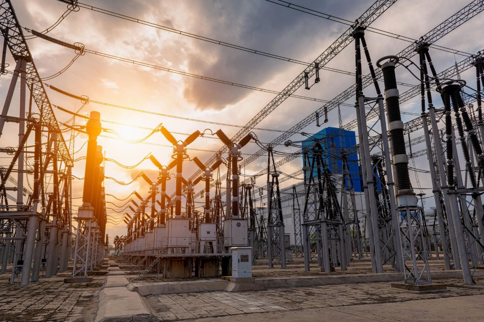
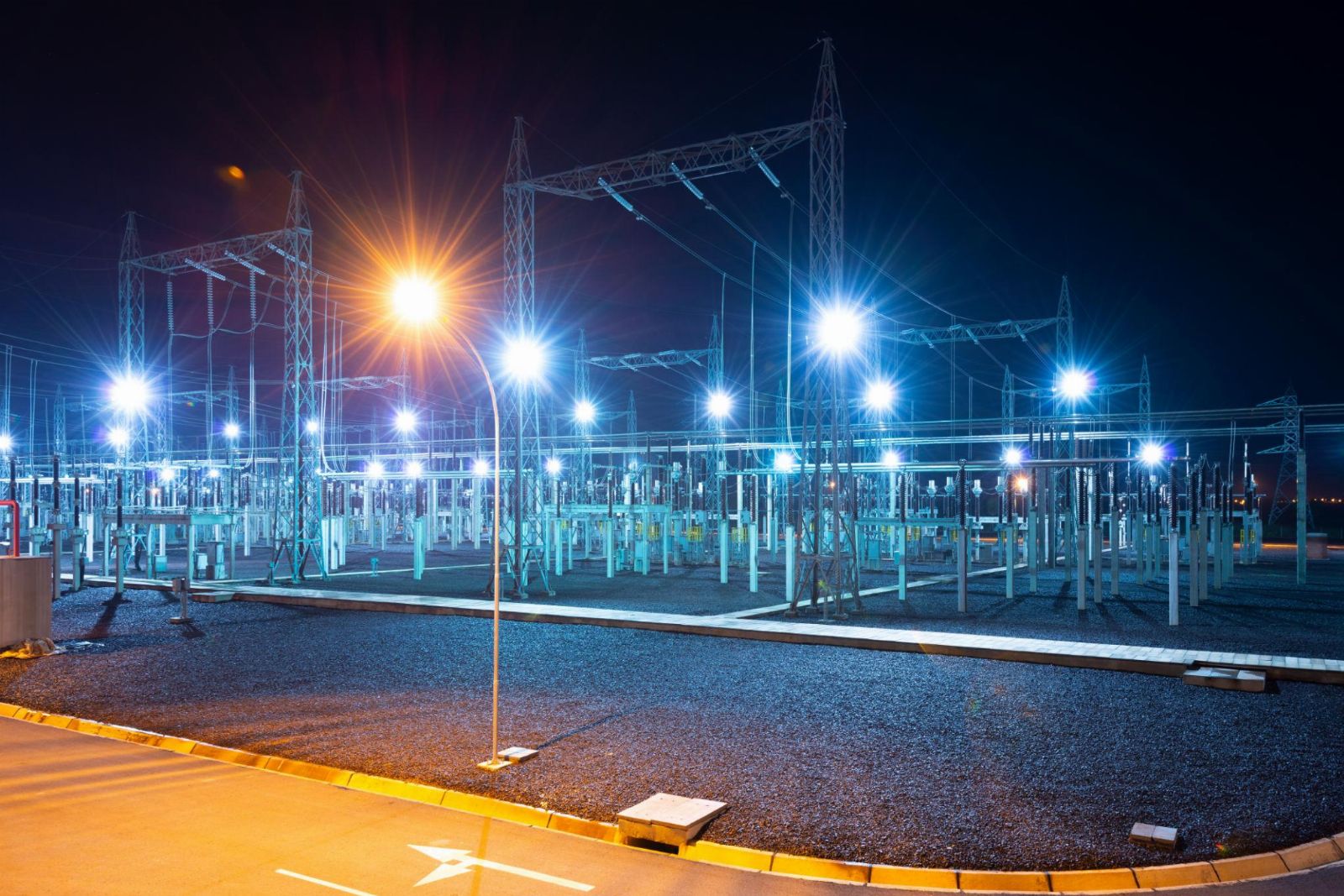
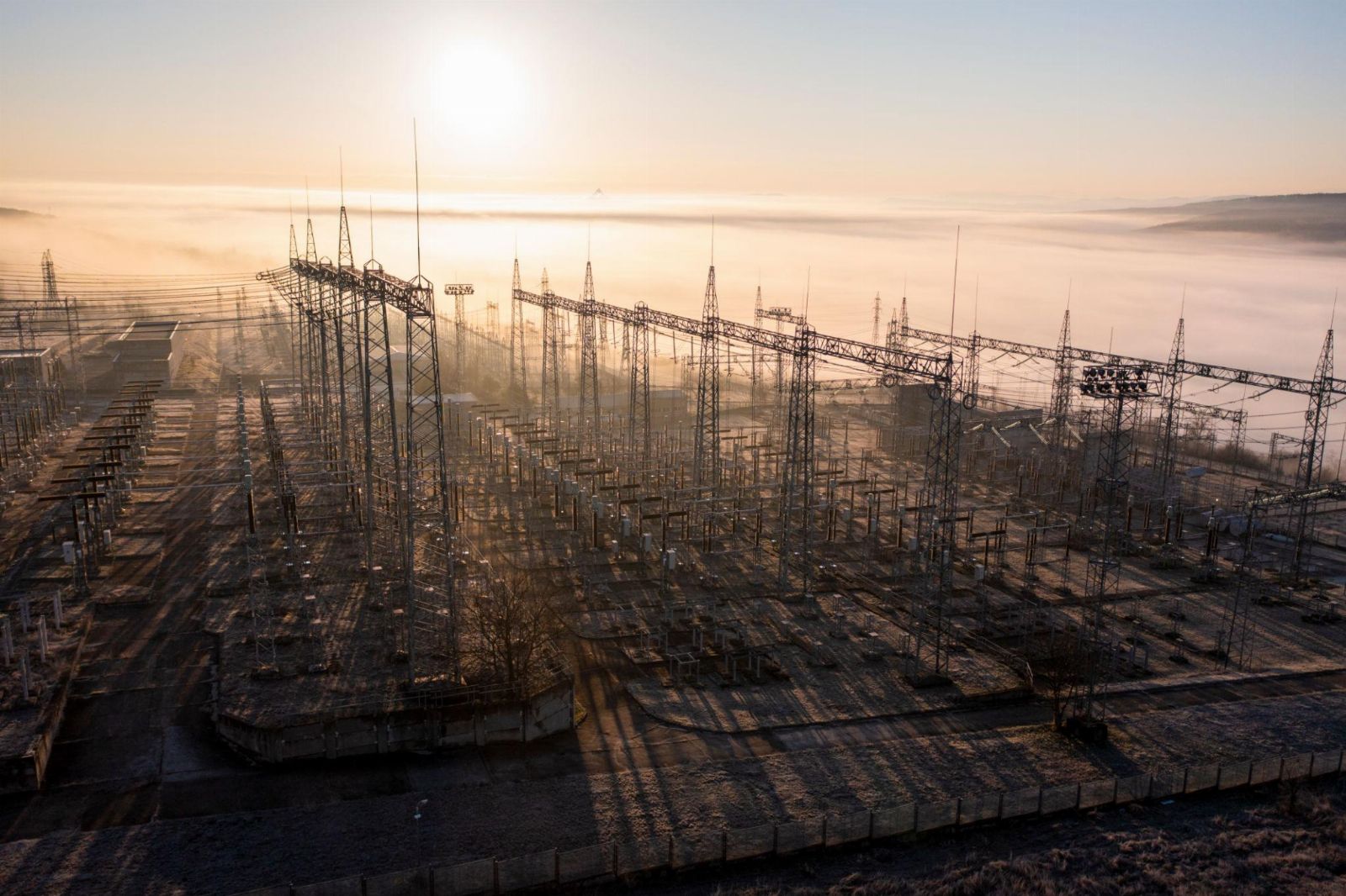
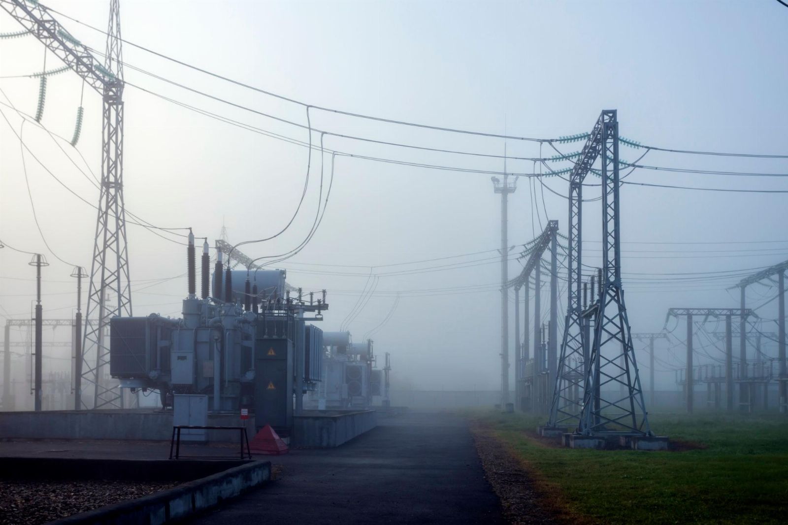
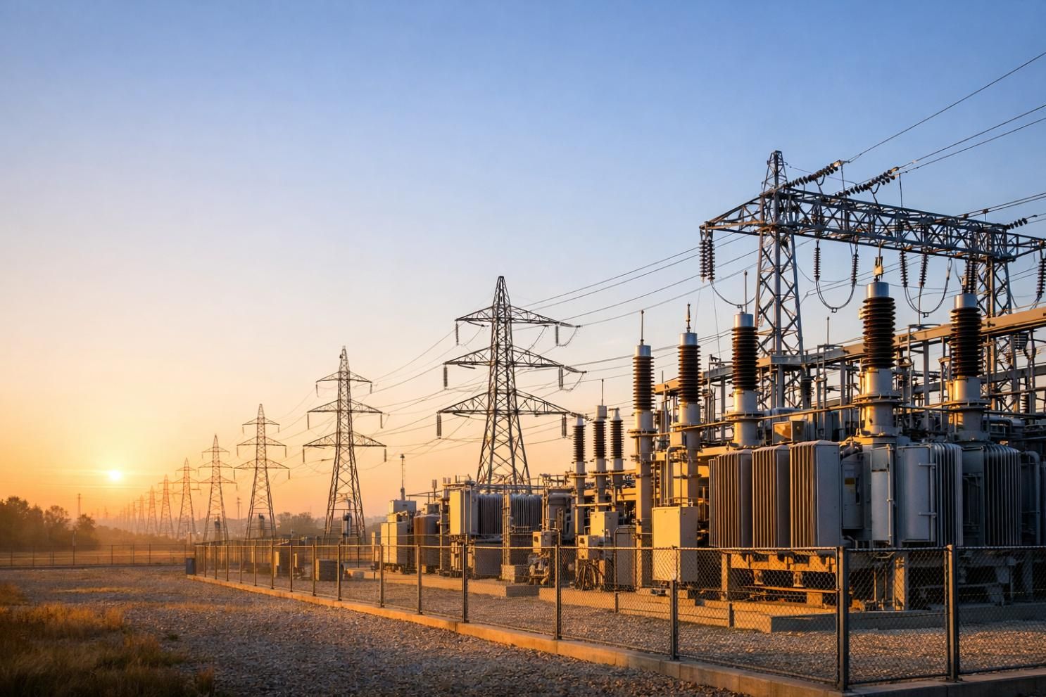
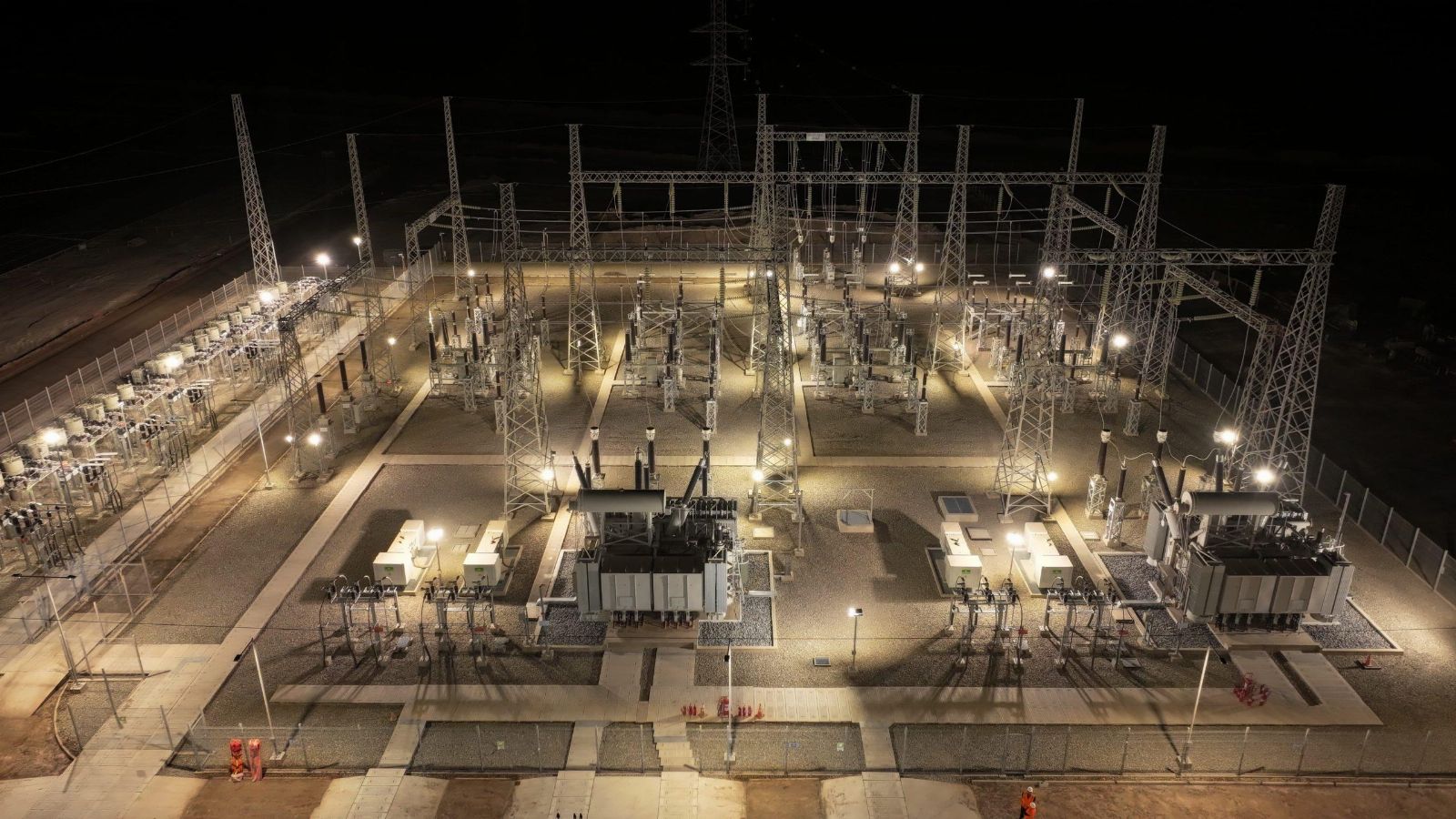
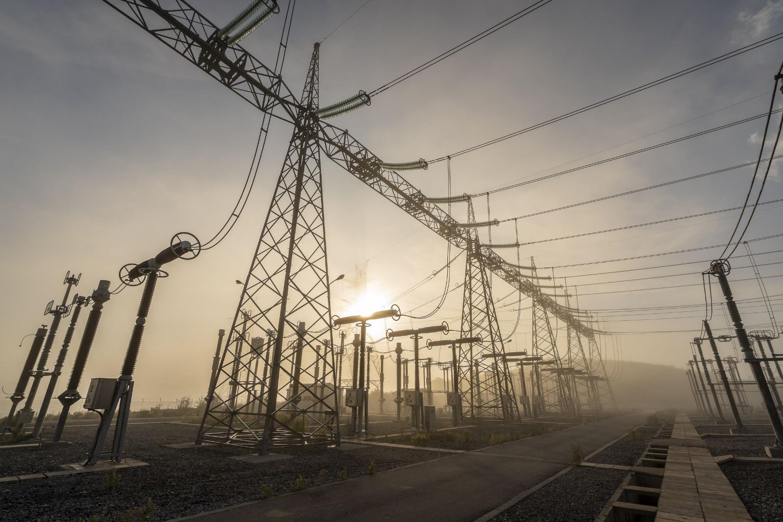
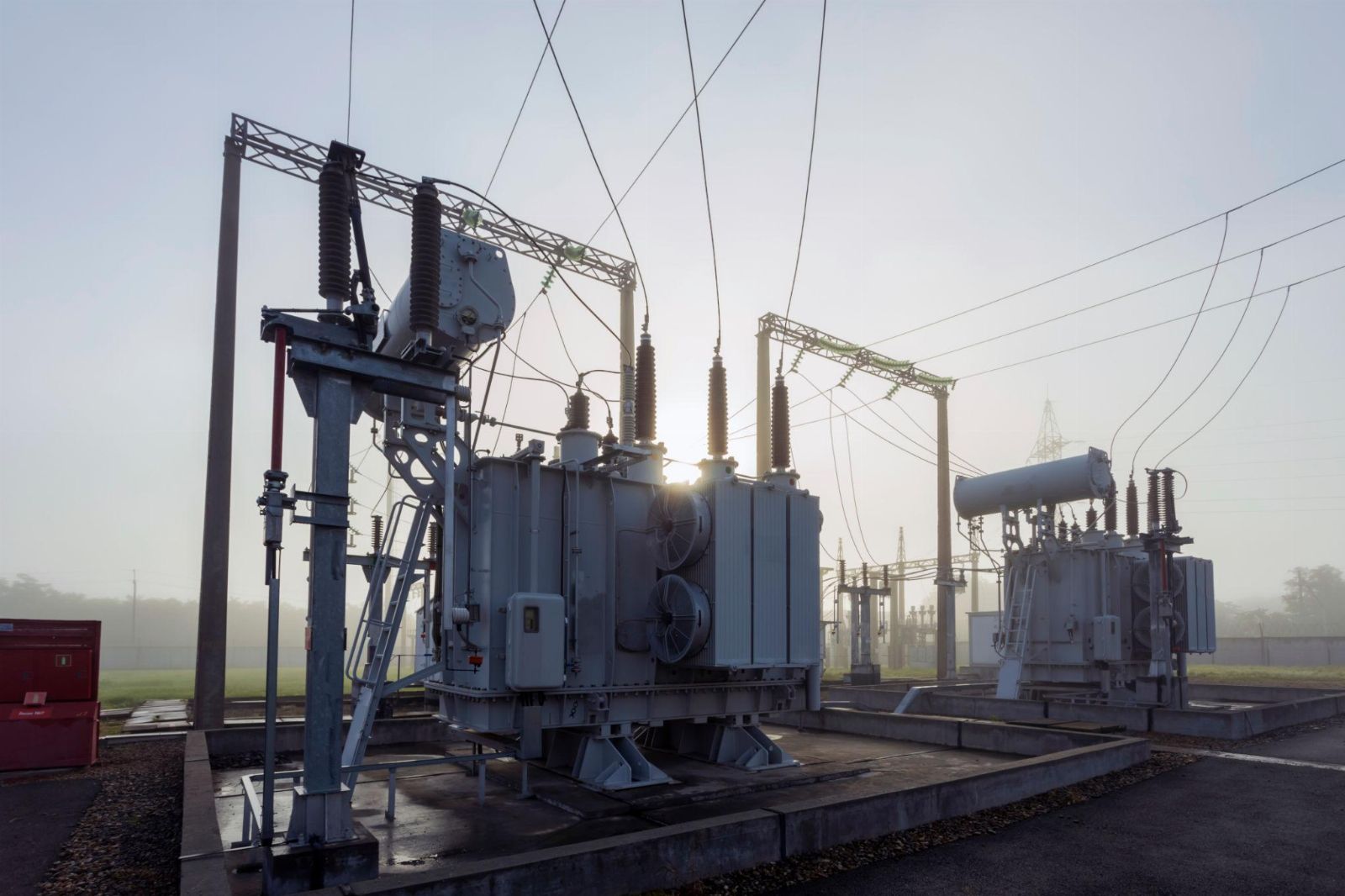
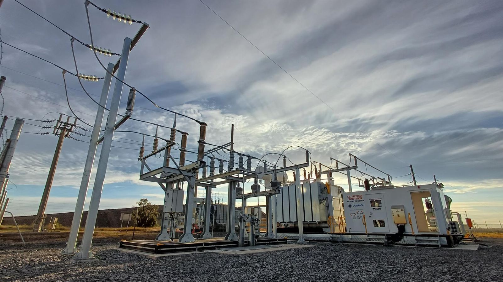
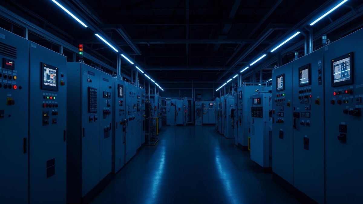
- We offer co-operation on replacement of old installed equipment on equipment at substations with new equipment produced at your factory. We have a large database of documentation for old, end-of-life equipment, and we will adapt your products to replace the old.

- Design of substation equipment in accordance with the technical specifications.

- Design documentation for the manufacture of electrical equipment.

- 3-D models, product drawings, BOM.

- Preparation of technical documentation for participation in tenders.

- Preparation of preliminary standards for material consumption for cost calculation..

- Consulting on projects.

..since August 1998

Proekt-Energo

Area of activity:

- Design of low-voltage, middle-voltage and high-voltage electrical equipment of substations for voltages of 0.4 - 220 kV.
- Development of working documentation in accordance with the technological capabilities of the plant.
- Preparation of preliminary technical documentation for participation in tenders for the supply of equipment.
- Consultations on project approvals.
- Supporting the production of equipment at the plant.

Specialization:

- Switchgear for indoor and outdoor installation for voltages of 6, 10, 20, 35 kV.
- Air-insulated secondary switchgears AIS for voltages 6, 10 kV.
- Complete transformer substations CTS for voltage 10 - 220 kV.
- Disconnectors for voltage 0.4 ... 220 kV.
- Drive to disconnectors.
- Replacement of withdrawable elements and switches in existing switchgear (Retrofit).
- Low-voltage switchgears for voltage 0.4 kV.
- DC 600V switchgears RU-600.

YAKNO (PKKZ-10) Standalone Outdoor Mining Switchgear Cubicle

The YAKNO-10 (PKKZ-10) standalone outdoor mining switchgear cubicle is a ready-to-deploy solution for receiving and distributing three-phase 50 Hz electrical power at 6/10 kV in open-pit mines and concentrator plants. It is intended for connection to 6/10 kV overhead lines and operation in main and branch feeders of pit infrastructure. Structurally, it is a splash-proof metal cubicle (IP34) with double-sided access, partitioned into independent compartments for the disconnector, medium-voltage circuit breaker, voltage transformer and control, featuring a comprehensive system of mechanical interlocks and a convenient serviceable relay panel for commissioning and maintenance.

Purpose and applications

YAKNO (PKKZ-10) supplies excavator fleets, drilling and pumping units, crushing and screening complexes, conveyor lines, and connection nodes of in-pit transmission lines. The cubicle switches and protects outgoing feeders to rotating machines (motors), power transformers and auxiliary distribution boards, supporting both local and remote control of feeder apparatus. Typical schemes such as “overhead line - cable feeder,” “cable - cable,” as well as sectioning of overhead lines with single- or double-ended supply enable flexible adaptation to pit network topology and project development stages.

The solution is designed for use within the distribution systems of power plants and industrial substations in the mining and metals sector, at connection points for mission-critical agricultural and industrial consumers, and as part of temporary/mobile power packages where rapid installation, redeployment and reliable medium-voltage switching are required.

Technical data

Rated voltage, kV 6; 10
Rated busbar current, A 630; 1000; 1600
Rated short-time withstand current (3 s), kA 20; 25; 31.5
Rated peak (dynamic) withstand current, kA 51
Environmental class (EN/IEC 60721-3-4) Outdoor (replaces GOST 15150 U1)
Degree of protection per IEC 60529 IP34 (splash-proof)
Walk-in service aisle None (non-walk-in)
Type of MV line terminations Cable, overhead (air)
Rated insulation level (IEC 60071-1 / IEC 62271-1) Standard insulation level
Withdrawable elements None (fixed-mounted)
Overall dimensions, mm
- width
- depth
- height

1000
1800
2500

Service conditions

The cubicle is intended for outdoor operation per EN/IEC 60721-3-4, in ambient temperatures from -45…-40 °C up to +50 °C, at installation altitude up to 1000 m above sea level, under mechanical stresses typical for open-pit sites, in a non-hazardous, non-aggressive atmosphere with controlled dust levels. The enclosure protection class is IP34 to IEC 60529, confirming splash-proof robustness suitable for open pit areas.

Space heaters are provided in the relay compartment and breaker operating mechanism; for low-temperature service, automatic anti-condensation heating can be enabled to maintain a set temperature, reducing moisture risk and ensuring consistent switching at sub-zero conditions. For installation above 1000 m, apply altitude correction factors to insulation and test levels per insulation-coordination practice (IEC 60071-1).

Layout and construction

The YAKNO (PKKZ-10) enclosure is a heavy-duty, fully welded steel housing with anti-corrosion coating. The interior is partitioned by solid barriers into functional compartments to localize faults and raise personnel safety. Each compartment has a dedicated door with latching hardware and mechanical interlocks. A perforated viewing screen provides visual indication of disconnector blade position; doors have opening limiters and are secured in a safe position during service.

The disconnector compartment includes a line disconnector with earthing blades, through-type insulators, and metal-oxide surge arresters (MOV) for lightning and switching-surge protection. A positive mechanical interlock couples the main and earthing shafts to prevent mal-operation during switching. The breaker compartment is equipped with a vacuum circuit breaker from leading manufacturers, current transformers (including a zero-sequence/core-balance CT), a three-phase voltage transformer (VT/PT), interlocking devices, and surge arresters to protect outgoing feeders. The control compartment contains disconnector drives, a removable/swiveling relay panel with protection-and-control (PAC), metering and indication, plus lighting and a service outlet.

For overhead-line entry, line-post insulators and an intake crossarm are used; for cable feeders, a sealed cable termination with optional side entry and provision for clamping two cables (as per execution). The zero-sequence CT design allows repositioning near the cable entry; optional skid rails enable a mobile/skid-mounted variant for quick relocation within the pit. All live bus parts are copper with a minimized number of bolted joints and plated contact surfaces to reduce contact resistance and operating losses.

For seamless project integration, removable elements (crossarm, insulators, skids) are provided for transport, with full device and wire marking, a single-line diagram on the inside of the control-door, and dedicated pads/bolts for connection to the site earthing grid. Sealing of revenue-metering circuits and a packing list are supplied in the O&M package.

Safety and interlocking

Personnel safety is ensured by a multi-layer concept: segregated compartments; inter-device mechanical interlocks (disconnector/earthing/breaker/doors); protective screens preventing access to live parts; and work practices for switching and application of portable earthing per recognized procedures. Interlocks enforce the prescribed sequence of operations; operating forces are limited and access to MV compartments is blocked when apparatus is energized.

Executions and options

Available executions include: overhead or cable entry, cable or overhead exit; line sectioning (single- or double-ended supply); cubicles with a power transformer up to 40…63 kVA and LV outgoing feeders; combined solutions with rotating-machine protection. Vacuum circuit breakers are standard; oil/SF6 breakers can be supplied to project specification. Options include additional earthing blades on the outgoing line, surge arresters, space heaters, temperature sensors, active/reactive energy metering, remote control and diagnostics.

Typical configurations

  • Overhead-line entry - cable feeder exit (motor, transformer and 6/10 kV switchboard section feeders).
  • Cable - cable (nodes linking main and branch cable lines; rotating-machine protection).
  • Overhead - overhead for line sectioning with single- or double-ended supply.
  • Cable entry - overhead exit (feeders to mobile consumers).
  • Overhead-line entry with power transformer up to 40…63 kVA and LV outgoing feeders (local auxiliary supply).

Standards compliance

Design and manufacture consider applicable test and acceptance rules and the following standards:

  1. IEC 60529: Degrees of protection provided by enclosures - IP Code (cubicle rating: IP34, splash-proof).
  2. EN/IEC 60721-3-4: Classification of environmental conditions - stationary use at non-weatherprotected locations (outdoor; replaces GOST 15150 U1).
  3. IEC 62271-200: A.C. metal-enclosed switchgear and controlgear for 1…52 kV - general requirements and type tests.
  4. IEC 62271-1 and IEC/EN 60071-1: Common requirements and insulation coordination - rated insulation levels and test duties.
  5. IEC 61936-1 and EN 50522: Power installations exceeding 1 kV AC and earthing of power installations (for installation and earthing practices).

Partnering with contractors and OEMs

We welcome cooperation with electrical installation contractors, component manufacturers (circuit breakers, CTs/VTs, surge arresters, drives, PAC), and investors planning localized production of YAKNO (PKKZ-10) cubicles using our documentation. Localization of selected modules, end-to-end quality procedures and certification support are available, including alignment with IEC 62271-200 for export projects.

Documentation and engineering support

We provide preliminary tender documentation, detail drawings, 3D models (AutoCAD, SolidWorks), DXF/DWG/Parasolid formats, main and auxiliary wiring diagrams, data sheets, specifications, spare-parts lists and lists of removable elements. Documentation can be adapted to project requirements and customer manufacturing capabilities (fixed installation or skid-mounted execution). For existing substations with third-party equipment, we prepare compatible solutions and transition parts, including relay panels and cable terminations.

Protection, control and metering

PAC is tailored to the feeder function. For “motor” loads: instantaneous overcurrent, overload protection, earth-fault protection and undervoltage. For “transformer” loads: instantaneous and time-overcurrent, earth-fault protection and overload. Included are measurements (voltmeter, ammeter), active-energy metering (and reactive on request), heater control for relay compartments, and inputs for external trip commands. The relay panel is removable/swiveling for ease of service.

Why work with us

- Reduced engineering burden: a complete documentation set enables assembly and commissioning by mid-level engineers with our process support.
- Fast series launch: we factor in routine and type test requirements, allowing batch production without lengthy pilot prototypes.
- Medium-voltage switchgear expertise: we select apparatus (VCB, CT/VT, surge arresters, drives), configure PAC to feeder type, and ensure alignment with IEC 62271-200 for export markets.

For additional information on YAKNO please contact: inbox@proekt-energo.com

As is well known, an error made at the design stage costs tenfold in manufacturing and a hundredfold in operation. Compliance with IEC/EN requirements, correct apparatus selection and PAC settings are investments in reliability and safety.

PDF – Download YAKNO technical information

pdf

K-6 (K-VI) Outdoor Metal-Enclosed Medium-Voltage Switchgear

The KRUN K-6 (K-VI) outdoor metal-enclosed medium-voltage switchgear is intended for the reception and distribution of three-phase AC power at 50 Hz with rated voltages of 6 and 10 kV. It is used in auxiliary switchboards of power plants, at substations of utility grids and industrial facilities, for the power supply of agricultural consumers, and in the oil & gas sector. The KRUN K-6 (K-VI) is assembled from individual cabinets with a splash-proof enclosure and two-sided service; each cabinet is divided into functional compartments to enhance reliability, personnel safety, and ease of operation.

Purpose and Applications

KRUN K-6 (K-VI) is designed for receiving and distributing three-phase power at industrial frequency 50 Hz with nominal voltages of 6 and 10 kV. The assembly is applied as 6–10 kV distribution switchgear at substations and auxiliary switchboards of power plants, at industrial and infrastructure sites, as well as for supplying critical agricultural consumers and along long transmission corridors.

Typical tasks: incoming feeders and bus sectionalizing of 6–10 kV networks; supplying outgoing feeders (cable and overhead); connection of 6/0.4 kV power transformers and station auxiliaries; measurement and revenue metering; building outdoor distribution points and package substations.

Technical Data

Rated voltage, kV 6; 10
Highest operating voltage, kV 7.2; 12
Rated current of main circuits, A 630; 1000; 1600
Rated busbar current, A 630; 1000; 1600
Short-time (3 s) withstand current, kA 20; 25; 31.5
Peak (1 s) withstand current, kA 51
Environmental classification EN/IEC 60721-3-4
Degree of protection (IEC 60529) splash-proof IP34
Service aisle no service corridor (two-sided access)
Type of MV line connections cable; overhead
Insulation level standard insulation (per IEC 62271-1 / IEC 60071-1)
Withdrawable elements fixed-mounted (no withdrawable truck)
Overall dimensions, mm
  - width
  - depth
  - height

1000
1800
2500

Operating Conditions

By environmental factors the equipment corresponds to EN/IEC 60721-3-4 (outdoor, non-weather-protected locations); enclosure protection level - IP34 (IEC 60529). For similar cabinets in the K-III series the environmental category is also specified as outdoor; the IP34 degree of protection is confirmed in the typical parameter tables.

Typical ambient temperature range for outdoor cabinets of this class corresponds to EN/IEC 60721-3-4 solutions: from -40…-45 °C up to +45 °C (cold-climate versions use anti-condensation/heating kits and the appropriate “cold” category). For the KRN-IV-10 series the lower limit is stated as -45 °C, and for open-air installation -40…+45 °C.

By mechanical environmental factors the assembly corresponds to class 4M4 per EN/IEC 60721-3-4; insulation and dielectric requirements follow IEC 62271-1 / IEC 60071-1. The enclosure degree of protection is defined by IEC 60529.

For installation above 1000 m a.s.l., apply altitude correction factors to insulation withstand levels as commonly required for medium-voltage switchgear (IEC 62271-1 guidance).

Layout and Construction

Each KRUN K-6 (K-VI) cubicle is made in a splash-proof metal enclosure and divided into independent compartments: disconnector & busbar compartment; medium-voltage circuit-breaker (VCB) compartment; incoming/outgoing feeder compartment; relay compartment; control compartment. This zoning confines any fault to a single compartment and ensures safe servicing.

The disconnector & busbar compartment houses oil/air bushing insulators, the disconnector, and busbars; a removable mesh viewing screen behind the door enables visual position check of the blades with doors closed. The MV circuit-breaker compartment accommodates a vacuum circuit-breaker and a space heater; with cable entry, zero-sequence current transformers (CBCT) can be installed.

The control compartment includes operating mechanisms for the busbar and line disconnectors (PR-10), and lighting; the relay compartment holds protection, automation, signaling and measuring devices, as well as mechanical interlock mechanisms. Access to all compartments is via doors with multi-point latches and provisions for padlocking.

The RVZ disconnector is operated by two PR-10 mechanisms: one linked by tie-rod to the main blade shaft, the other to the earthing blade shaft; a mechanical interlock between shafts prevents closing of the earthing blades when the main blades are closed. The VCB is operated by push-buttons and/or a manual mechanism (for certain VCB types).

Terminations: bottom cable entry and/or side/rear bus connections via busducts/adaptors; front panels can provide voltage presence indicators and test sockets for phasing checks.

Cabinet earthing is performed by welding the base frame to the site grounding grid; metallic parts of built-in devices are bonded to the enclosure via earthing bars/star washers/sliding contacts.

Safety and Interlocking

The assembly includes a system of mechanical and electromechanical interlocks preventing incorrect operations and ensuring safe access to compartments. Operation with faulty interlocks is prohibited; before work, absence of voltage must be verified and portable earthing applied - in accordance with applicable safety rules and local procedures.

Key interlocks: blocking of earthing-blade closing when main blades are closed; access blocking to compartments for incorrect disconnector/earthing positions; door latching with rod mechanisms; cross-interlock between operating shafts; blocking of any movement of withdrawable parts (if present) without connected secondary circuits; optional key and electronic interlocks for busbar earthing switches.

Typical safe-access sequence: open the VCB; open the disconnector; close the earthing blades; open the relevant compartment door; verify absence of voltage; remove the mesh guard if required.

For additional protection, arc-flash detection systems (optical/pressure) with pressure-relief flaps can be used to reduce arc energy and localize damage.

Variants and Options

KRUN K-6 (K-VI) cabinets are configured to project needs. The composition may include vacuum circuit-breakers from various manufacturers and the following options:

  • Vacuum circuit-breakers: ABB VD4, Schneider Electric Evolis, Alstom/GE HVX/ECA; rated currents 630…3150 A (depending on series).
  • Current transformers for protection, measurement and metering; zero-sequence CTs (CBCT).
  • Voltage transformers (single-phase UGE/Y12G or equivalents); HV fuses; busbar earthing switches.
  • Surge arresters on incomers/busbars.
  • Protection & control: electromechanical relays and digital IEDs (Sepam, MiCOM, SPAC, Orion, etc.); metering - any modern meter types.
  • Voltage presence indicators and test/phasing sockets.

Typical Configurations

KRUN K-6 (K-VI) is assembled from individual panels (incoming, bus sectionalizer, feeder, VT, station-service, etc.). VCB panels include line and bus disconnectors, the VCB, current transformers; surge arresters and zero-sequence CTs are available per specification. The VT panel contains a voltage transformer with a bus disconnector and fuses, plus busbar earthing blades; the station-service (SS) panel contains a 25/40 kVA transformer with protective device.

  • VCB panel - vacuum circuit-breaker panel (cable/bus/overhead entry).
  • Bus sectionalizer - CB/disconnector for bus sectionalizing and redundancy.
  • VT panel - voltage-transformer panel (with fuses and bus disconnector).
  • SS panel - station-service transformer 25/40 kVA with protective device.

Standards Compliance

  • EN/IEC 60721-3-4 - environmental classification (outdoor, non-weather-protected).
  • IEC 60529 - degrees of protection of enclosures (IP code; for KRUN K-6 - IP34).
  • IEC 62271-200 - AC metal-enclosed switchgear and controlgear, 1–52 kV.
  • IEC 62271-1 / IEC 60071-1 - insulation requirements and insulation co-ordination.
  • IEC 61936-1 - power installations exceeding 1 kV AC (design & erection).

Working with Contractors and Partners

We welcome cooperation with manufacturing sites, investors and EPC contractors. On request we will configure the optimal KRUN K-6 (K-VI) architecture for your project - from auxiliary switchgear of TPPs/HPPs to distribution points along overhead lines and oil & gas fields. Adaptation to breakers and protection devices available in your market is provided, as well as localization of metalwork and assembly, and support during type/acceptance tests and commissioning.

If needed, we can organize manufacturing of individual assemblies on a cooperative basis (enclosures, busducts, VT/SS panels, cable entries), supply of spares, and training of production staff. For sites with special conditions - selection of anti-corrosion coatings, heating/ventilation kits, air filtration, and snow-retention for service platforms.

Documentation Delivered

Each KRUN K-6 set is supplied with a complete package of factory and working documentation sufficient for manufacturing, installation and operation:

  • Product data sheet; Operation manual/Technical description; primary and secondary schematics; connection diagrams; operating documents for components.
  • Full set of fabrication drawings for the cabinet metalwork, assemblies and parts; bills of materials and purchased components; paint maps and coating requirements.
  • 3D models and exchange files for your CAD: DWG/DXF (AutoCAD), SLDPRT/SLDASM (SolidWorks), STEP/Parasolid; installation sketches, external wiring diagrams, cable and terminal lists.
  • Factory test programs and procedures, test reports, protection settings lists, and templates for operational interlock cards.

Why Work with Us

- No need to maintain a large team of highly qualified design engineers - you receive a documentation set that can be executed by an engineer of average qualification.
- No need to build prototypes - our experience allows immediate launch of serial production.
- Working to our documentation - your specialists receive support on all nuances of manufacturing KRUN K-6.

For additional information on KRUN K-6 please contact: inbox@proekt-energo.com

…and as is well known - an error made at the design stage leads to ten-fold costs in manufacturing, and a hundred-fold in operation…

PDF - Download KRUN K-6 Technical Information.

pdf
  • 1
  • 2
  • Regulatory and technical documentation

    Regulatory and technical documentation

  • 3-D models

    3-D models

  • Operating manual for equipment

    Operating manual for equipment

  • Operating manual for equipment

    Operating manual for equipment

  • Technical specifications

    Technical specifications

  • Technical specifications

    Technical specifications

  • Operating manual for equipment

    Operating manual for equipment

  • 3-D models

    3-D models

  • Equipment drawings

    Equipment drawings

  • Equipment drawings

    Equipment drawings

  • Technical specifications

    Technical specifications

  • Equipment drawings

    Equipment drawings

  • Regulatory and technical documentation

    Regulatory and technical documentation

  • Regulatory and technical documentation

    Regulatory and technical documentation

  • 3-D models

    3-D models

Demo

FEEDBACK FORM