Working design documentation for the manufacture of electrical equipment for substations. 3D models. Drawings. Regulatory documentation.

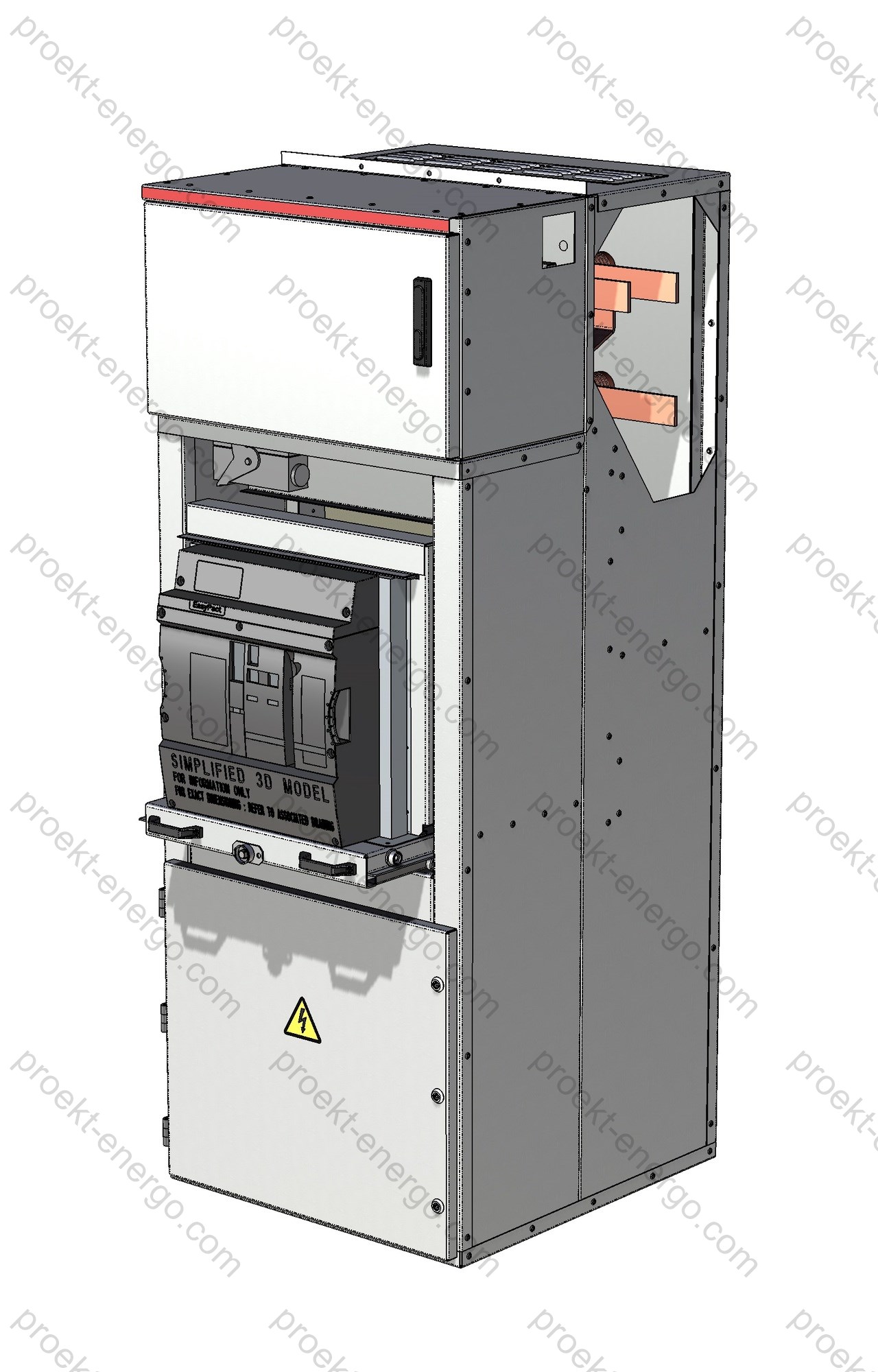
KSO-20 Single-front metal-enclosed switchgear 20 kV (AIS metal-enclosed)

Purpose and application

KSO-20 are modular single-front metal-enclosed switchgear panels 20 kV (AIS metal-enclosed) for receiving, distributing, and switching three-phase power at 50 Hz. Voltage series per IEC 60038: rated 20 kV with maximum operating 24 kV (Series I). The solutions target networks with isolated, resonant-earthed (compensated) or effectively earthed neutral at distribution and industrial power facilities: indoor MV substations (primary/secondary), auxiliary switchboards of power plants, and supply hubs for transport, logistics, and utilities. Supply options include installation in permanent buildings and integration into factory-built modular container stations.

Functionally, KSO-20 covers incoming and sectional panels with circuit breaker, feeder panels, transformer feeders, metering/measurement panels, reactive-power compensation, and ATS/AR (automatic transfer/reclose) sections. The single-front concept provides access to all controls and indications from the front, allowing rows along walls and efficient use of switchroom floor area. A unified busbar system and connection interfaces simplify scaling to reliability Categories I–III.

Service conditions

Base climatic category — U3 per GOST 15150; project-specific U1/U2/UHL, etc., are available considering temperature, humidity, altitude, and site corrosion category. Typical enclosure degree of protection — IP31 per GOST 14254 (IEC 60529). Where required, local IP of individual compartments can be increased while maintaining thermal regimes and ventilation.

The voltage class is certified to MV standards: Ur = 24 kV (maximum operating voltage for 20 kV equipment). Insulation levels, air clearances and creepage distances are project-validated for lightning/switching overvoltages and short-circuit forces, including thermal/dynamic withstand of main circuits.

Layout and design solutions

The series uses sectional separation into three isolated compartments: busbar, apparatus and cable. Segregation improves fault containment, simplifies maintenance, and mitigates consequences of abnormal events. For the 20 kV class, increased insulation distances and reinforced bus supports are provided. The busbar system consists of series-connected copper bar segments on insulating supports; provisions are made for bus barriers/bushing insulators for safe section coupling and “two-row” rooms with bus bridges.

The apparatus compartment is withdrawable (drawout): 24 kV vacuum circuit breaker, CTs/VTs; on request — fuse block or combined module. Operation is possible with the door closed; truck withdrawal is permitted only with the breaker open and after releasing the operational interlock. The cable compartment is primarily for bottom cable entry (top entry available); supports and clamps for armoured cables are provided, along with points for test plugs and sensors for lug temperature. The secondary compartment accommodates microprocessor IEDs for protection/automation, ATS/AR, metering, terminal blocks, and telecontrol; harness routing is organised in cable ducts with allowance for upgrades.

The enclosure is available in two manufacturing concepts: a welded steel frame with powder coating, or a weld-free body of hot-coated steel (Z/ZA/AZ/ZM) per EN 10346 with bolted/riveted joints. The latter offers high corrosion resistance and dimensional stability for series production; coating is selected per required service life and site corrosion category.

For control and monitoring, the front hosts a mimic diagram with LED indication of drives and circuits, internal compartment lighting, and an auxiliary socket for a portable lamp. On request, a VDIS voltage-presence indication system (IEC 62271-213) with LRM interface is implemented for portable voltage/phase comparators and integration into the interlock logic.

Safety and interlocking

Priority — process safety: all breaker operations with the door closed; no switching of disconnectors with the breaker closed; no earthing switch closing on live circuits; no truck withdrawal with the breaker closed; no access to HV compartments without applying earths. Inter-panel trapped-key interlocking is available for coordinated operations across multiple panels/sections. For personnel protection per IEC 62271-200, continuity category LSC (up to LSC2B), partition class PM/PI, and internal arc classification IAC (e.g., AFL/AFLR with appropriate equipment and type tests) are specified.

Versions and options

  • Main switching device. 24 kV vacuum circuit breakers with interrupting ratings matched to calculated SC currents and protection settings (IEC 62271-100). Load break switches and contactors (IEC 62271-106) and “breaker-fuse” combinations (IEC 62271-105) are permissible — for transformer feeders and special duties.
  • Disconnectors and earthing switches. Devices per IEC 62271-102 with required mechanical/dynamic withstand; sectional/bypass circuits for maintenance modes.
  • Protection, automation and communications. Microprocessor IEDs for lines/transformers/sections, autoreclose/automatic transfer/load-shedding; integration via IEC 60870-5-104 and IEC 61850, PQ data export, support for local and supervisory SCADA.
  • Measurement and metering. CTs/VTs per IEC 61869 series accuracy classes, revenue/technical meters, power-quality monitoring systems.
  • Diagnostics and monitoring. Sensors for lug and bus temperatures, arc-flash sensors, breaker operation counters, partial-discharge monitoring — integrated into a predictive diagnostics system.
  • Enclosure and environmental robustness. Two-coat powder paint or hot metallic coatings Z/ZA/AZ/ZM per EN 10346; seals and fire-rated penetrations per specification; seismic analysis/testing options per project category.
  • Cable infrastructure. Cables per IEC 60502-2 (6–30 kV) with terminations/test kits; bus bridges and cable links between sections.

Typical configurations

Based on standard schemes, configurations include “incoming — section — feeders”, “two 20 kV incomers with ATS”, “incoming — transformer — feeder”, “incoming — section — section — feeders”, etc. For refurbishment of existing switchboards, transition panels and interface-dimension compatibility are provided. Project options include LSC up to LSC2B and PM/PI partitions, enabling isolation of individual feeders for maintenance without de-energising adjacent feeders within the selected category.

Partnering with contractors, OEMs and investors

We offer flexible cooperation models for localisation and serial manufacture of KSO-20: supply of metal kits (enclosures, doors, drawout trucks, busbar assemblies), licensing of design documentation, outsourcing of harnesses and mounting panels, support for type/qualification tests (including internal arc and functional safety), and staff training.

Documents

  • Tender package: single-line diagrams, equipment lists, data sheets, compliance matrices, 3D visualisations, and a design note with effort estimate, delivery schedule, risk matrix, and mandatory test list.
  • Manufacturing drawings and 3-D models: assembly drawings for enclosure/modules, specifications, main/secondary schematics, cable registers, purchased-parts lists, routing sheets. Formats — DWG/DXF, STEP/Parasolid; models — for AutoCAD, SolidWorks, Inventor.
  • Interlocking schemes and safety: inter-panel and intra-panel logics, key interlocks, safe operation sequences, signal/condition tables, VDIS and arc-flash protection integration into the overall system.
  • Commissioning and operation: insulation test programs, verification of secondary circuits, protection IED settings, pre-commissioning/commissioning reports, O&M schedules, torque charts, lists of control measurements and diagnostic tests.
  • Module/parts cooperation: sourcing contractors for enclosures, busbar systems, wiring harnesses and mounting panels; agreement of tolerances, coatings and marking; organisation of incoming/in-process QC.

Standards compliance

Design, manufacture and testing of KSO-20 take into account (depending on configuration and selected devices): IEC 62271-200; IEC 62271-1; IEC 62271-100; IEC 62271-102; IEC 62271-105; IEC 62271-106; IEC 61869 series; IEC 60038; GOST 15150; GOST 14254 (IEC 60529); EN 10346; IEC 60502-2.

Technical data

Rated voltage, kV 20
Maximum operating (Ur), kV 24
Rated current of main circuits, A 630; 800; 1250; 1600
Rated busbar current, A 630; 1250; 1600
Short-time withstand current (3 s), kA 25; 31.5
Peak withstand current (amplitude), kA ≈63; ≈80
Rated fuse current, A up to 200
Rated breaking capacity of 24 kV fuses (example 200 A), kA up to 63
Climatic category and installation class per GOST 15150 U3 (others — project-specific)
Degree of protection per GOST 14254 (IEC 60529) IP31 (higher locally — per spec)
Overall dimensions, mm
— width
— depth
— height

650–1000
1035–1250
≈2300–2600 (selected versions up to ~3020)

We will supply a complete set of engineering materials — from the tender package to shop-ready drawings and instructions for manufacture, assembly, and commissioning. Documentation is adapted to the project requirements, selected device OEMs, and your plant’s capabilities. If you do not plan in-house fabrication of modules/parts, we will organise cooperation for enclosures, drawout trucks, busbar systems, wiring harnesses, and mounting panels. Final assembly, electrical installation, and testing are performed at your site under our technical supervision.

  • Preliminary technical documentation for tenders: single-line diagrams, equipment lists, questionnaires, standards compliance sheets, 3D models and renderings, and a design note with estimates of effort, schedule, and risks.
  • Working drawings and 3-D models: assembly drawings, main and secondary schematics, bills of materials, purchased-parts lists, cable registers; formats — DWG, DXF, STEP, Parasolid; models — for AutoCAD, SolidWorks, Inventor.
  • Interlocking schemes and algorithms: inter-panel/intra-panel logics, key interlocks, safe operation sequences, signal/condition tables, integration of VDIS and arc-flash protection into the overall system.

Why work with us

You do not need an expanded engineering staff: the drawing set enables a mid-level engineer to launch serial production without costly prototypes. We support the project end-to-end — from agreeing SC calculations and selecting apparatus to IEC/GOST to training assembly and operating staff in safe switching, interlocking, crimping techniques, and torque-tightening charts.

For more information on KSO-20 contact: inbox@proekt-energo.com

PDF — Download KSO-20 technical information

pdf

KSO-220

Single-front medium-voltage switchgear KSO-220

Single-front metal-enclosed switchgear KSO-220 for 6–10 kV is intended for the reception, distribution and switching of three-phase 50 Hz AC power in systems with isolated, compensated or effectively earthed (grounded) neutral. The design belongs to the class of medium-voltage metal-enclosed switchgear and ensures a high level of personnel safety, installation efficiency and maintainability when used as part of indoor switchgear (indoor substations), package transformer substations and modular block-type substations. The panels are oriented toward long-term operation with minimal downtime and support modernization and staged expansion of existing switchboards.

Typical applications of KSO-220:
- indoor switchgear of package transformer substations (prefabricated substations);
- substations of industrial facilities;
- auxiliary switchgear of power plants;
- municipal and infrastructure facilities (water and heat utilities, metro systems, etc.);
- distribution points, supply centers and sectioning nodes of urban and industrial networks;
and other power-supply installations.

KSO-220 can be installed both in permanent indoor substation buildings and in specially designed factory-built modular enclosures. Each panel is a bolted/riveted sheet-metal framework of corrosion-resistant steel (including hot-dip galvanized versions) using riveted and/or non-welded fasteners. Service is provided from one side for single-row or back-to-back layouts. A panel with a vacuum circuit-breaker for a key feeder includes segregated compartments - low-voltage (relay), withdrawable unit (apparatus), busbar and cable - enabling selective access and localization of possible fault conditions.

The relay compartment, the withdrawable unit compartment and the cable compartment have individual doors with keyed access. The relay compartment is segregated from the primary circuits and accommodates protection, metering and telecontrol equipment. Withdrawable units include vacuum circuit-breakers, bus-section disconnectors and drawout voltage-transformer trucks. The truck has three positions: service (main and auxiliary circuits engaged), test (main circuits open, auxiliaries engaged) and maintenance (all circuits open, truck fully on the service platform).

A system of interlocks eliminates hazardous operations:
- prohibition of moving the withdrawable unit between service and test positions with the breaker closed;
- prohibition of breaker closing with the truck in an intermediate position;
- interlock against racking in/out with plug-in contacts under load;
- prohibition of transfer from test to service with the earthing (grounding) switch closed;
- prohibition of closing the earthing switch in service or intermediate positions (allowed only in test);
- interlock of the cable-compartment door when the earthing switch is open;
- interlock of the feeder door with a load-break switch when the earthing switch is open;
- closed-door operation of the breaker; device positions are visible through viewing windows and mechanical indicators.

Purpose and application

KSO-220 is used to build incoming, bus-section and outgoing feeder connections of 6–10 kV distribution networks; to connect power transformers; to distribute power via cable and overhead lines; to connect reactive-power compensation banks, process drives and special loads. The cubicles implement protection and automation functions (instantaneous/time overcurrent, earth-fault, sensitive earth-fault, autoreclosing, automatic transfer, etc.), as well as commercial/technical metering and remote control/monitoring through standard dispatching interfaces (SCADA/DCS). The modular concept enables scalable indoor switchgear, bypass bus arrangements, sectioning, bus bridges between rooms, and implementation of incomer redundancy without major enclosure redesign.

Service conditions

Standard environmental category - EN/IEC 60721-3-3 (indoor, weather-protected locations in temperate climates). Default degree of protection - IP31 (selected nodes optionally IP41/IP54 subject to thermal management). Degrees of protection are defined by IEC 60529 (IP Code). Enhanced requirements for dust/moisture, condensation and corrosion are met by installing filter-fan units, space heaters, sealed cable glands and protective coatings; permissible temperature/humidity ranges and service altitude follow the general specifications for switchgear and controlgear in IEC 62271-1.

Layout and construction

The KSO-220 design provides functional segregation into low-voltage (relay), apparatus/withdrawable-unit, busbar and cable compartments. Inter-compartment metal partitions, shutters and screens prevent access to live parts when the apparatus is racked out. Primary busbars (copper/aluminium) and contact joints are rated for the declared short-circuit thermal/dynamic stresses; provisions are made for CTs/VTs, arc/temperature sensors, current inlets and bus bridges. The relay compartment is segregated from primary circuits and houses protection IEDs, measuring devices, communication modules and DC auxiliary power sources. The cable compartment has independent earthing points, cleats/brackets for cable fixing and a dedicated area for safe termination of screens/armours.

Safety and interlocking

Personnel protection combines mechanical and electrical interlocks, clear visual indication and organizational measures. On request the panels are supplied with internal arc classification (IAC) with accessibility class (A) and directions (F/L/R - front/side/rear) for a specified current/time (e.g., IAC AFLR 20 kA 1 s). The methodology and acceptance criteria for internal-arc tests of metal-enclosed switchgear 1–52 kV are defined by IEC 62271-200. In practice, it is recommended to state IAC requirements explicitly in the specification because under IEC they belong to type tests performed upon user request.

Versions and options

  • Incoming/bus section - vacuum circuit-breaker or disconnector; ATS/AR implementation; measurement and metering.
  • Outgoing feeder - withdrawable circuit-breaker, CTs/VTs, protection IED (IOC/TOC/SEF/EF), telecontrol (Modbus RTU/TCP, IEC 60870-5-104, IEC 61850).
  • Transformer feeder - switch-fuse combination to IEC 62271-105 or circuit-breaker with protection; gR/aR fuses selected to transformer power and prospective fault currents.
  • Reactive-power compensation - capacitor-bank feeder with appropriate switching and protections for stepped/dynamic cos φ control.
  • Disconnectors/earthing switches - per IEC 62271-102 for indoor installations; motor drives and remote interlocking available.
  • Switches/load-break switches - per IEC 62271-103 (switching without short-circuit interruption), including three-pole drawout versions.
  • Instrument transformers - selection and placement per IEC 61869-2 (CTs) and IEC 61869-3 (VTs) to ensure correct metering and protection performance.
  • Enhanced enclosure protection - local facias/compartments at IP41/IP54, anti-corrosion finishes, sealed cable entries to IEC 60529.

Typical configurations

  • Single-section busbar system with one incomer and a group of feeders; line or transformer backup can be implemented.
  • Two-section busbar system with a bus-section circuit-breaker and automatic transfer on incomers; bus bridges between switchboards are possible.
  • Bypass bus arrangement for maintenance without interruption to critical loads.
  • Module for packaged substation - a set of KSO-220 panels in a climate-controlled container with ventilation, gas relief and integrated micro-climate systems to IEC 62271-202.
  • Commercial metering node - dedicated cubicle with VTs/CTs, metering cabinet and communication channels to AMR/SCADA.

Compliance with standards

Design, manufacture and testing of KSO-220 are carried out to applicable international and harmonized standards for 6–10 kV medium-voltage switchgear (to be confirmed for each project):

  • IEC 62271-200 - AC metal-enclosed switchgear and controlgear for 1–52 kV (incl. internal-arc classification, IAC).
  • IEC 62271-1 - Common specifications for switchgear and controlgear >1 kV (applies to MV equipment 1–52 kV).
  • IEC 62271-102 - AC disconnectors and earthing switches.
  • IEC 62271-103 - AC switches/load-break switches for 1–52 kV.
  • IEC 62271-105 - Switch-fuse combinations for 1–52 kV.
  • IEC 60529 - Degrees of protection (IP Code).
  • IEC 61869-2/-3 - Instrument transformers (CTs and VTs) for measurement and protection.
  • IEC 60071-1 - Insulation coordination: selection of withstand voltage levels.
  • IEC 62271-202 - Prefabricated substations for AC 1–52 kV (for containerized indoor switchgear).

Technical characteristics

Rated voltage, kV 6; 10
Highest voltage for equipment (Um), kV 7.2; 12
Rated current of main circuits, A 400; 630; 1000; 1600
Rated busbar current, A 630; 1000; 1600
Short-time withstand current (3 s), kA
- with vacuum circuit-breaker
- with load-break switch


20; 31.5
16; 20
Peak withstand current (1 s), kA
- with vacuum circuit-breaker
- with load-break switch


51; 80
31.5; 63
Environmental category (EN/IEC 60721-3-3) EN/IEC 60721-3-3
Degree of protection to IEC 60529 IP31
Overall dimensions, mm
- width
- depth
- height

750; 800
850
2100

We offer documentation to manufacture KSO-220:

- Preliminary technical documentation for tender participation: single-line diagrams, equipment lists, short-circuit calculations, data sheets, explanatory notes and a delivery plan.
- A full “production-ready” design/fabrication package for your plant: specifications and lists of purchased components, assembly drawings, sheet-metal flat patterns/bend tables, connection and wiring diagrams, cable schedules, protection-settings tables, FAT/SAT programs and acceptance checklists.
- If you have no in-house metalworking, we assist with cooperation: selection of subcontractors for laser cutting/bending and powder coating, procurement of busbar fittings and cabinet hardware; supply of primary and secondary devices with factory certificates.
- Adaptation of documentation to project requirements, local regulations and your manufacturing capabilities; support of initial series and personnel training.

  • 3D models and assemblies: SolidWorks (SLDPRT/SLDASM), Parasolid (x_t/x_b), STEP, IGES - for BIM/PLM integration.
  • Drawings and flat patterns: AutoCAD (DWG), DXF - for laser cutting, stamping and sheet-metal bending.
  • Secondary-circuit packages: schematic and connection diagrams, signal lists, terminal/wire tables, HMI templates.
  • Protection IED configurations and exchange files (CID/SCD) per IEC 61850, settings for IEC 60870-5-104/Modbus, test reports and settings logs.
  • Installation & commissioning manuals, procedures to verify interlocks and arc protection, operation & maintenance instructions.

Why work with us

- No need to maintain a large engineering staff: we provide a production-ready design package that can be executed by a mid-level engineer following the instructions.
- Faster time-to-series: a library of proven subassemblies allows you to avoid or minimize a “zero series”.
- Technology support: consulting on protection-relay commissioning, interlock verification, protocol setup (Modbus/IEC 60870-5-104/IEC 61850), preparation of FAT/SAT programs, and support for certification and production audits.

For more information on KSO-220 contact: inbox@proekt-energo.com

…and, as is well known, an error made at the design stage costs tenfold in manufacturing and a hundredfold in operation.

Documents

PDF - Download KSO-220 technical information

pdf

КСО-319

KSO-319 Single-front Medium-Voltage Metal-Enclosed Switchgear

The KSO-319 single-front medium-voltage switchgear (rated for 6–10 kV) are modular cubicles for receiving, distributing, and switching three-phase AC power at 50 Hz in systems with isolated, effectively earthed, or solidly earthed neutral. The equipment is intended for indoor air-insulated switchgear (AIS) of packaged transformer substations (PTS), industrial substations, plant auxiliary switchgear of power stations, municipal utilities and urban infrastructure, as well as other power-supply facilities. The cubicles can be installed both in permanent indoor substations and in rapidly deployable factory-built modular blocks, which significantly shortens implementation time and reduces civil/installation scope.

Purpose and application

Functionally, KSO-319 forms incomer, bus-section, and feeder connections of medium-voltage switchgear. The cubicles provide: switching of 6–10 kV transformers and lines; busbar sectioning with automatic transfer capability; supply of plant auxiliaries and process loads; energy metering; signalling and data exchange with monitoring and SCADA/DCS systems. During brownfield upgrades, KSO-319 is convenient thanks to unified mating dimensions, transition panels, and coordinated busbar centerlines-this eases interfacing with installed equipment and enables staged commissioning of renewed sections without prolonged outages.

Service conditions

Base environmental category - EN/IEC 60721-3-3 (indoor, weather-protected, replaces GOST 15150 U3). The design accounts for temperature, humidity, dust, as well as storage and transportation conditions. Degree of enclosure protection - IP20 per IEC 60529, preventing access to hazardous live parts and ingress of solid objects. Project-specific local increases of IP in individual compartments (e.g., apparatus) are possible subject to thermal and ventilation calculations. For high-altitude sites, the effect of reduced air pressure on dielectric strength is considered in insulation clearances and acceptance test methods per the general requirements for switchgear.

Layout and construction

The KSO-319 enclosure is supplied in two main variants: (a) a welded structural-steel frame with powder-polymer coating for high mechanical durability and long-term protection; (b) a bolt/rivet-assembled design made of galvanized/Al-Zn steel for fast assembly, manufacturability, and service convenience. The cubicle is divided into functional compartments: busbar (main busbars and inter-panel links), apparatus (circuit-breaker, disconnector, earthing switch), cable (entries, terminations, current transformers), and a low-voltage compartment (protection and control IEDs, measuring instruments, marshalling panels). Viewing windows on the front provide visual indication of device positions; internally, a service light and a receptacle for a portable lamp are provided. For measuring circuits, current and voltage transformers per the IEC 61869 series (incl. Parts 2 and 3) are recommended to ensure proper accuracy classes, thermal/dynamic withstand, and compatibility with modern protection and metering IEDs.

Safety and interlocking

KSO-319 incorporates mechanical interlocks that prevent hazardous or incorrect operations: blocking disconnector operation with the circuit-breaker closed; blocking closing of the earthing switch with the disconnector closed; blocking disconnector closing when the circuit is earthed; blocking door opening unless the earthing switch is positively engaged. Circuit-breaker operation is performed with the door closed, reducing personnel risk during switching. Requirements for sequence of operations, drive endurance, insulation distances, and verification tests follow IEC 62271-1 general provisions and the relevant product parts IEC 62271-100 (AC circuit-breakers) and IEC 62271-102 (disconnectors and earthing switches). For sites with higher safety demands, arc-resistant versions with confirmed Internal Arc Classification (IAC) and accessibility types AFLR/ALR/AR per IEC 62271-200 can be provided, routing energy to safe zones.

Versions and options

The KSO-319 range includes incomers, bus-section panels (with breaker or disconnector), feeder panels, VT/CT panels, metering, plant auxiliaries, as well as bus-tie (coupler) panels. Available options:
- vacuum circuit-breakers with endurance and interrupting ratings per IEC 62271-100;
- manual and motor operators; fixed or withdrawable arrangements;
- microprocessor protection IEDs (differential, directional, autoreclose/automatic transfer), disturbance recorders;
- digital integration per IEC 61850: MMS for supervisory exchange, GOOSE/SMV for high-speed events/measurements over station/process bus;
- additional industrial-safety measures: arc-flash detection, temperature monitoring of busbars and cable lugs, partial discharge monitoring;
- corrosion-resistant coatings, insulation/heaters, seismic versions, extended spare-parts kits, and standardized bus links.

Typical configurations

Proven schemes for 6–10 kV AIS based on KSO-319:
1) Incomer - connection of a transformer or MV line; metering; automatic transfer;
2) Bus-section - bus sectioning to improve maintainability and contingency flexibility; with breaker or disconnector;
3) Feeder - outgoing cable/overhead lines with full protection suites and I/U diagnostics;
4) VT/CT panel - supply for measuring circuits, commercial/technical metering, system monitoring;
5) Plant auxiliaries - supply of DC/AC auxiliaries, life-support systems of the switchgear, and control circuits;
6) Bus coupler/tie - bus links for flexible network topology, redundancy, and bypass modes during maintenance.

Compliance with standards

  • IEC 62271-200:2021 and Amd.1:2024 - AC metal-enclosed switchgear 1–52 kV; construction requirements, internal arc confirmation, accessibility types.
  • IEC 62271-1:2017 - Common specifications for high-voltage switchgear and controlgear (service conditions, insulation levels, type tests).
  • IEC 62271-100:2021 and Amd.1:2024 - AC circuit-breakers: endurance, interrupting capability, test duties.
  • IEC 62271-102:2018 - AC disconnectors and earthing switches: requirements for drives and interlocks.
  • IEC 61869-2/-3 - Instrument transformers (CTs/VTs): additional requirements and accuracy classes for protection and metering.
  • IEC 61850 - MMS/GOOSE/SMV communication services for digital substations and SCADA/DCS.
  • IEC 60529 - Degrees of protection (IP code).
  • EN/IEC 60721-3-3 - Environmental conditions for stationary use in weather-protected locations (replaces GOST 15150 U3).

Engaging contractors, manufacturers, and investors

We are open to cooperation with manufacturers of switchgear and HV/MV equipment, EPC contractors, and investors interested in localizing production of medium-voltage cubicles. A technological documentation package is provided for industrialization: material and purchased-parts specifications, quality-control plans, assembly and commissioning instructions, coating/galvanizing requirements, and typical routines for routine/functional tests. A phased transition is possible-from screwdriver assembly to full-cycle production (enclosures, busbars, coating)-including staff training and production-process audits. This approach enables serial launch without costly prototypes and minimizes validation risks.

Documents

A complete set of design and shop documentation is available for KSO-319: data sheets, single-line and functional diagrams, purchased-parts lists, assembly drawings and detailing, cable schedules, and nameplate/label templates. File formats: AutoCAD (DWG/DXF), SolidWorks (SLDPRT/SLDASM), Parasolid (X_T/X_B). On request, we adapt to your production capabilities (press-brake, stamping, welding, powder coating), corporate standards, and digital interfaces (IEC 61850 data models and services for SCADA/HMI integration).

Operation and maintenance

The closed-door breaker operation concept reduces injury risk and makes switching predictable. Modularity and unified parts simplify spares management and speed up post-fault recovery. Options include arc-flash protection, temperature monitoring of busbars and cable lugs, and partial-discharge monitoring. Maintenance routines are set considering breaker duty statistics, disturbance recorder data, and the requirements proven by type tests.

Technical data

Rated voltage, kV 6; 10
Highest system voltage, kV 7.2; 12
Rated current of main circuits, A 400–2000
Rated busbar current, A 630–2000
Thermal short-time withstand current (3 s), kA 12; 20; 31.5
Peak withstand current (1 s), kA 51
Environmental category (replaces GOST 15150 U3) EN/IEC 60721-3-3
Degree of protection IP20 (IEC 60529)
Overall dimensions, mm
- width
- depth
- height

800
850
2250

- Preliminary technical package for tenders (data sheets, specifications, single-line/functional diagrams) for fast compliance checks and preparation of a commercial offer.
- Full design package and 3-D models to launch KSO-319 production at your site. If in-house enclosure and busbar fabrication is unavailable, we will arrange manufacturing at certified partner plants; your factory performs final assembly, routine/acceptance tests, and installation.
- Prompt document updates to your project requirements and manufacturing capabilities; support during component procurement, supervisory installation and commissioning; preparation of test programs (insulation - per the IEC 60060 series; functional - per applicable parts of IEC 62271).

Benefits of working with us

- No need to maintain a large team of highly qualified engineers: the documentation set is structured for confident work by a mid-level engineer.
- Serial production launch without building a prototype: a portfolio of proven solutions and unified modules enables immediate transition to repeatable batches.
- Support for digital integration: configuration of IEDs and communications per IEC 61850 (MMS/GOOSE/SMV), interaction with SCADA/HMI, optimization of secondary wiring and cable routing.

For additional information on KSO-319 please contact: inbox@proekt-energo.com

PDF – Download KSO-319 technical information

pdf

KSO-205 Medium voltage air insulated switchgear

KSO-205 - Single-front medium-voltage switchgear 10 kV

Single-front metal-enclosed switchgear 6–10 kV, type KSO-205, is intended for the reception and distribution of three-phase AC power at 50 Hz in networks with isolated or effectively earthed (grounded) neutral. The switchgear belongs to the class of medium-voltage metal-enclosed assemblies designed for long, safe operation as part of indoor switchgear (indoor substations), package transformer substations, and other power-supply facilities. The design focuses on high serviceability and rapid replacement of withdrawable units without extended downtime.

Typical applications of KSO-205:
- indoor switchgear of package transformer substations (prefabricated substations);
- substations of industrial facilities;
- auxiliary switchgear of power plants;
- municipal utilities;
- distribution points, supply centers, and sectioning nodes of urban and industrial networks;
and other power-supply installations.

KSO-205 panels can be installed both in permanent indoor substation buildings and in special factory-built modular enclosures. Each panel is a bolted/riveted sheet-metal structure made of hot-dip galvanized folded steel. KSO-205 provides single-front service with single-row or back-to-back layouts. A panel with a vacuum circuit-breaker features segregated compartments: low-voltage (relay) compartment, withdrawable unit compartment, busbar compartment, and cable compartment.

The relay compartment, the withdrawable unit compartment, and the cable compartment are closed by separate doors keyed alike. The relay compartment is segregated from primary circuits; protection and automation equipment is mounted inside and on its door. As withdrawable units the panels may use: a vacuum circuit-breaker; a sectionalizing disconnector; a voltage-transformer truck.

The withdrawable unit can be set to the following positions relative to the enclosure: service, test, and maintenance. In the service position, both main and auxiliary circuits are engaged and the unit is latched within the panel. In the test position, the main circuits are disconnected while auxiliary circuits remain engaged (disconnection of auxiliaries is permissible); the unit is fixed within the panel. In the maintenance position, both main and auxiliary circuits are disconnected and the unit is placed outside the panel on a service trolley.

The KSO-205 incorporates the following interlocks:
- an interlock preventing movement between service and test positions with the circuit-breaker closed;
- an interlock preventing circuit-breaker closing in the intermediate position (between service and test);
- an interlock preventing racking in/out of a unit with plug-in contacts under load;
- an interlock preventing racking from test to service with the earthing (grounding) switch closed;
- an interlock preventing closing of the earthing switch in service or intermediate positions (i.e., allowed only in the test position);
- a cable-compartment door interlock preventing door opening when the earthing switch is open;
- a door interlock on panels with a load-break switch preventing door opening when the earthing switch is open.

Purpose and application

KSO-205 panels are intended for reception, distribution, and switching of 6–10 kV electrical energy in power-supply systems of industrial, infrastructure, and energy facilities. Typical functions include: incoming and bus sectioning, outgoing feeders (cable and overhead), transformer feeders, capacitor banks, technological drives, as well as commercial and technical metering points. The panels support protection and automation functions (e.g., instantaneous/time overcurrent, earth-fault, autoreclosing, automatic transfer) and integration into SCADA/DCS via standard interfaces and protection relays (IEDs).

Service conditions

Standard environmental category - per EN/IEC 60721-3-3 (indoor, naturally ventilated locations in temperate climates). Enclosure degree of protection - IP31 to IEC 60529, providing protection against solid objects ≥ 2.5 mm and vertically falling drops of water. On request, increased degrees of protection can be provided for individual compartments (e.g., IP41/IP54), along with filters/louvered inlets, space heaters, and micro-climate sensors. Options are available for vibration and seismic performance, anti-corrosion finishes, and enhanced dust/moisture protection for special regions.

Layout and construction

The panel follows a modular concept with functional segregation into compartments: low-voltage (relay), withdrawable unit, busbar, and cable. Metal partitions/screens and mechanical shutters prevent access to live parts when the withdrawable unit is removed. Primary circuits are made with copper or aluminium busbars (bus ratings of 630/1000/1600 A depending on configuration); joints are designed for the short-time thermal and dynamic currents specified in the data table. The mounting framework uses perforated profiles to simplify installation of secondary wiring, current/voltage transformers, terminal blocks, and temperature/arc sensors.

Primary apparatus include vacuum circuit-breakers with mechanical/electrical endurance suitable for 6/10 kV distribution duty, as well as disconnectors, earthing switches, load-break switches, and combined switch-fuse units for the protection of small and medium-power transformers. Instrument transformers are applied per IEC 61869-2/-3 (or national harmonized standards), ensuring correct operation of metering devices and protection IEDs.

Safety and interlocking

Comprehensive safety is achieved through a combination of design measures and interlocks: mechanical (cam/lever mechanisms, key interlocks), electrical (limit switches, interlock circuits), and organizational (keyed access, labeling, safety signage). Viewing windows provide visual indication of the circuit-breaker and earthing-switch positions, as well as shutter and door status. On request, panels can be supplied with internal arc classification (IAC) with accessibility classes AFL/AFR/AFLR in accordance with IEC 62271-200; this option vents arc energy and by-products through pressure-relief systems to reduce risks to personnel and equipment.

Versions and options

The KSO-205 range covers incoming, bus-section, and feeder panels; transformer and capacitor-bank feeders. Options include: metering compartments with commercial metering nodes; switch-fuse combinations (for transformer protection 250–1600 kVA); sectionalizing devices with remote control; arc-flash sensors and fast trip devices; auxiliary power and DC panels; communication interfaces (Modbus, IEC 60870-5-104, IEC 61850) for dispatching; busbar redundancy; bus bridges and switchgear extensions. Supply as part of prefabricated modular substations (containerized indoor switchgear) is available in accordance with IEC 62271-202.

Typical configurations

  • Incoming/bus section - panels with a vacuum circuit-breaker or disconnector, current transformers for overcurrent/power protections, with the option to implement ATS/AR.
  • Feeder panel - withdrawable circuit-breaker, CTs/VTs, relay compartment with protection IED (IOC/TOC, definite-time/IDMT, earth-fault), terminals for 6–10 kV cable connections.
  • Transformer feeder - switch-fuse combination (or circuit-breaker with protection), VT for metering on the MV side, personnel earthing switch.
  • Metering cubicle - withdrawable VT truck, metering cabinet, interfaces for AMR/AMI systems.
  • Bypass/transfer - for bypassing lines/equipment during maintenance, fitted with disconnectors and mechanical interlocks.
  • Module for prefabricated substation - integration of multiple KSO-205 panels into a containerized solution with appropriate ventilation, heat removal, and fire-safety measures.

Compliance with standards

Design and manufacture of KSO-205 follow international and harmonized standards applicable to medium-voltage metal-enclosed switchgear. Key references include:

  • IEC 62271-200 - AC metal-enclosed switchgear and controlgear for 1–52 kV (incl. internal-arc classification, IAC).
  • IEC 62271-100 - AC circuit-breakers.
  • IEC 62271-102 - AC disconnectors and earthing switches.
  • IEC 62271-105 - Switch-fuse combinations for 1–52 kV.
  • IEC 62271-202 - Prefabricated substations for AC 1–52 kV (for containerized solutions).
  • IEC 60529 - Degrees of protection (IP Code).
  • EN/IEC 60721-3-3 - Environmental conditions for weather-protected stationary use (replaces GOST 15150 U3).
  • IEC 61869-2/-3 - Instrument transformers (CTs and VTs) for measurement and protection.
  • IEC 60071-1 - Insulation coordination: selection of withstand voltage levels for switchgear above 1 kV.

Technical data

Rated voltage, kV 6; 10
Highest voltage for equipment (Um), kV 7.2; 12
Rated current of main circuits, A 400; 630; 1000; 1600
Rated busbar current, A 630; 1000; 1600
Short-time withstand current (3 s), kA
- with vacuum circuit-breaker
- with load-break switch


20; 31.5
16; 20
Peak withstand current (1 s), kA
- with vacuum circuit-breaker
- with load-break switch


51; 80
31.5; 63
Environmental category (EN/IEC 60721-3-3) EN/IEC 60721-3-3
Degree of protection to IEC 60529 IP31
Overall dimensions, mm
- width
- depth
- height

800
850
2100

Documents

- Preliminary technical documentation for tender participation to manufacture KSO-205. We will prepare the information needed to assess feasibility against tender requirements and data sheets.
- Detailed fabrication package: working drawings, 3-D models, and all materials required to manufacture KSO-205 at your facility. If you do not plan to produce parts in-house, we will help outsource their fabrication. Final assembly and wiring are performed at your site.
- All documentation can be adapted to project requirements and to your plant’s manufacturing capabilities.
- If your substation has equipment from another manufacturer, we will prepare documentation to produce compatible panels to complement the existing installation.

Deliverables and files

  • Design and fabrication sets: schematic diagrams, single-line diagrams, wiring diagrams, cable schedules, BOMs and parts lists.
  • 3D models and assemblies: SolidWorks (SLDPRT/SLDASM), Parasolid (x_t/x_b), STEP, IGES - for BIM/PLM integration.
  • Drawings and flat patterns: AutoCAD (DWG), DXF - for laser/punch cutting and sheet-metal bending.
  • Protection & control settings and configurations: relay IED settings, HMI templates, IEC 60870-5-104/IEC 61850 protocols.
  • Installation & commissioning manuals, interlock check procedures, and FAT/SAT functional test programs.

Partnering with subcontractors

We welcome cooperation with manufacturers of electrical equipment, metal structures and LV panels, with engineering and installation companies, and with investors interested in localizing production of KSO-205 panels. Support packages include transfer of design/technical specifications, training for technologists and designers, support of initial series, production process audits, and assistance with certification tests. For regional markets we can align with local norms and standards, prepare type-test programs and FAT/commissioning procedures, and select components with favorable logistics.

Your benefits

- No need to maintain a large team of highly qualified engineering staff - you receive a complete documentation set that can be executed by mid-level engineers.
- No need to build prototypes - our experience enables immediate serial production, reducing time-to-market.
- Working to our documentation, your specialists receive consulting on all nuances of KSO-205 manufacturing, including protection relay commissioning and interlock verification, FAT/SAT programs, and preparation of operation manuals.

For more information on KSO-205 contact: inbox@proekt-energo.com

…and, as is well known, an error made at the design stage costs 10× in manufacturing and 100× in operation.

PDF - Download KSO-205 technical information

pdf

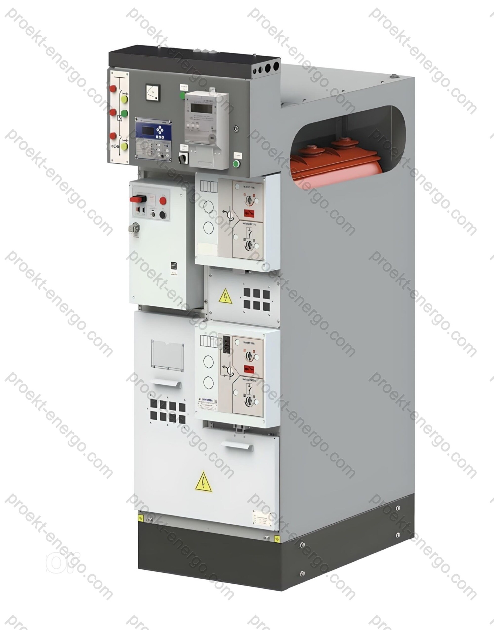
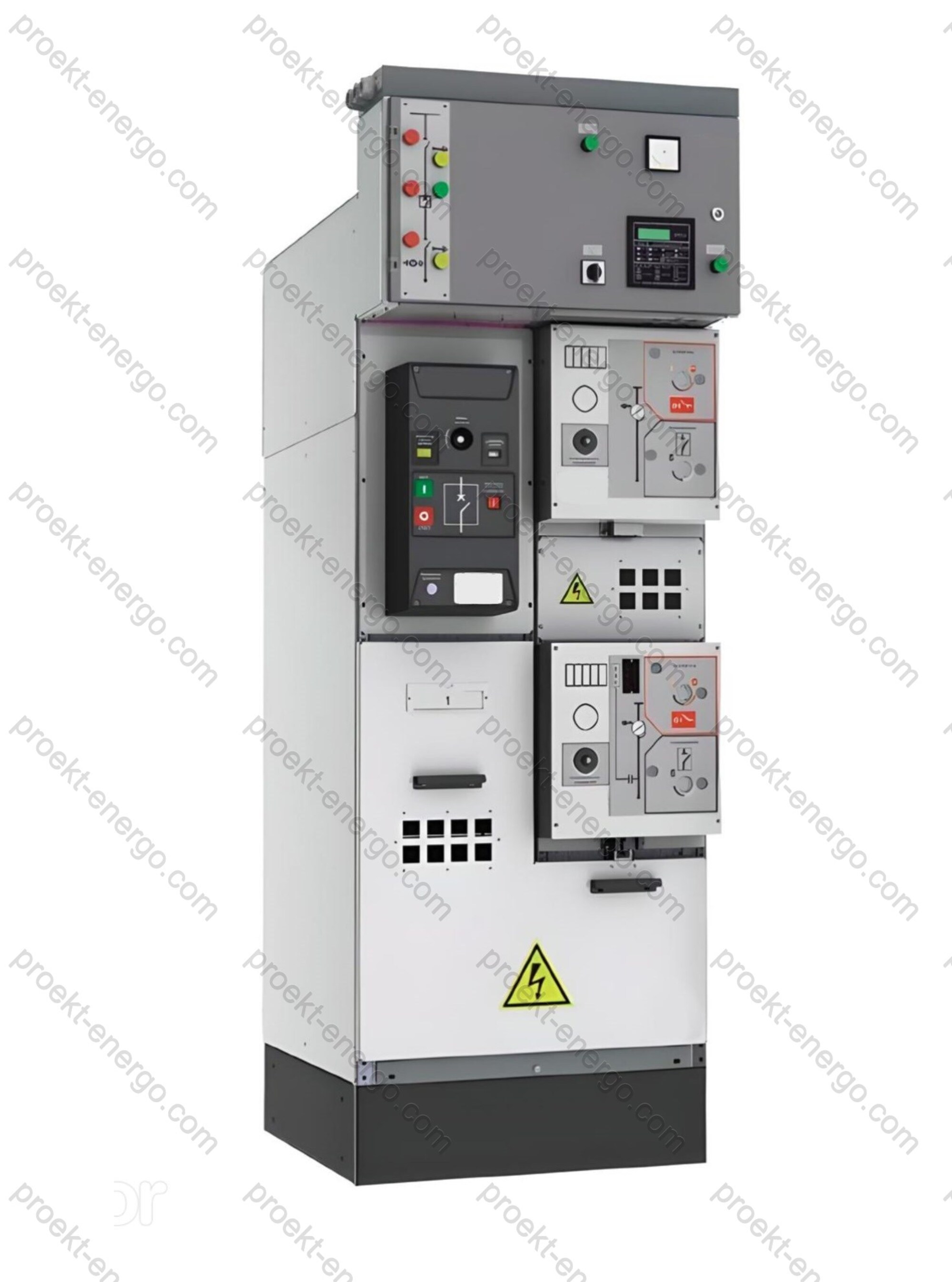
KSO-423 «Omega» Medium voltage air insulated switchgear

KSO-423 “Omega” Single-front Medium-Voltage Metal-Enclosed Switchgear

Purpose and application

KSO-423 “Omega” are modular single-front switchgear cubicles (metal-enclosed, air-insulated – AIS) for receiving, distributing, and switching three-phase AC power at 50 Hz for 6–10 kV systems. The series is intended for networks with isolated or effectively earthed neutrals at distribution utilities and industrial power facilities. Typical applications include indoor AIS of packaged transformer substations, industrial substations, plant auxiliary switchgear of power stations, and power centers for transport, logistics, and municipal infrastructure. The cubicles are supplied both for installation in permanent indoor substations and for integration into factory-built modular blocks, reducing commissioning time and total installed cost.

Functionally, KSO-423 “Omega” covers incomer and bus-section panels with a circuit-breaker, feeder panels, transformer feeders, metering and measuring panels, and-optionally-power-factor correction cubicles. Single-front service provides access to all controls and indications from the front, enabling rows of cubicles to be arranged along a wall and making efficient use of the switchroom footprint. Unified interfaces and a standardized busbar system allow easy scaling and adaptation to supply schemes of different reliability categories.

Service conditions

Base environmental category - EN/IEC 60721-3-3 (indoor, weather-protected; replaces GOST 15150 U3). Project-specific variants for other location categories (e.g., cold climate, tropical, enhanced corrosion resistance) are available with due account of temperature/humidity ranges, site altitude, and corrosion category. The typical degree of enclosure protection is IP31 per IEC 60529; local increases of IP for individual compartments can be provided subject to thermal and ventilation constraints.

Rated voltage series follows international practice: 6 kV (highest system voltage 7.2 kV) and 10 kV (highest system voltage 12 kV). Insulation levels and air clearances are selected to withstand lightning and switching overvoltages; electrodynamic forces and thermal effects under short-circuit currents are considered in line with the specified thermal and peak withstand ratings.

Layout and construction

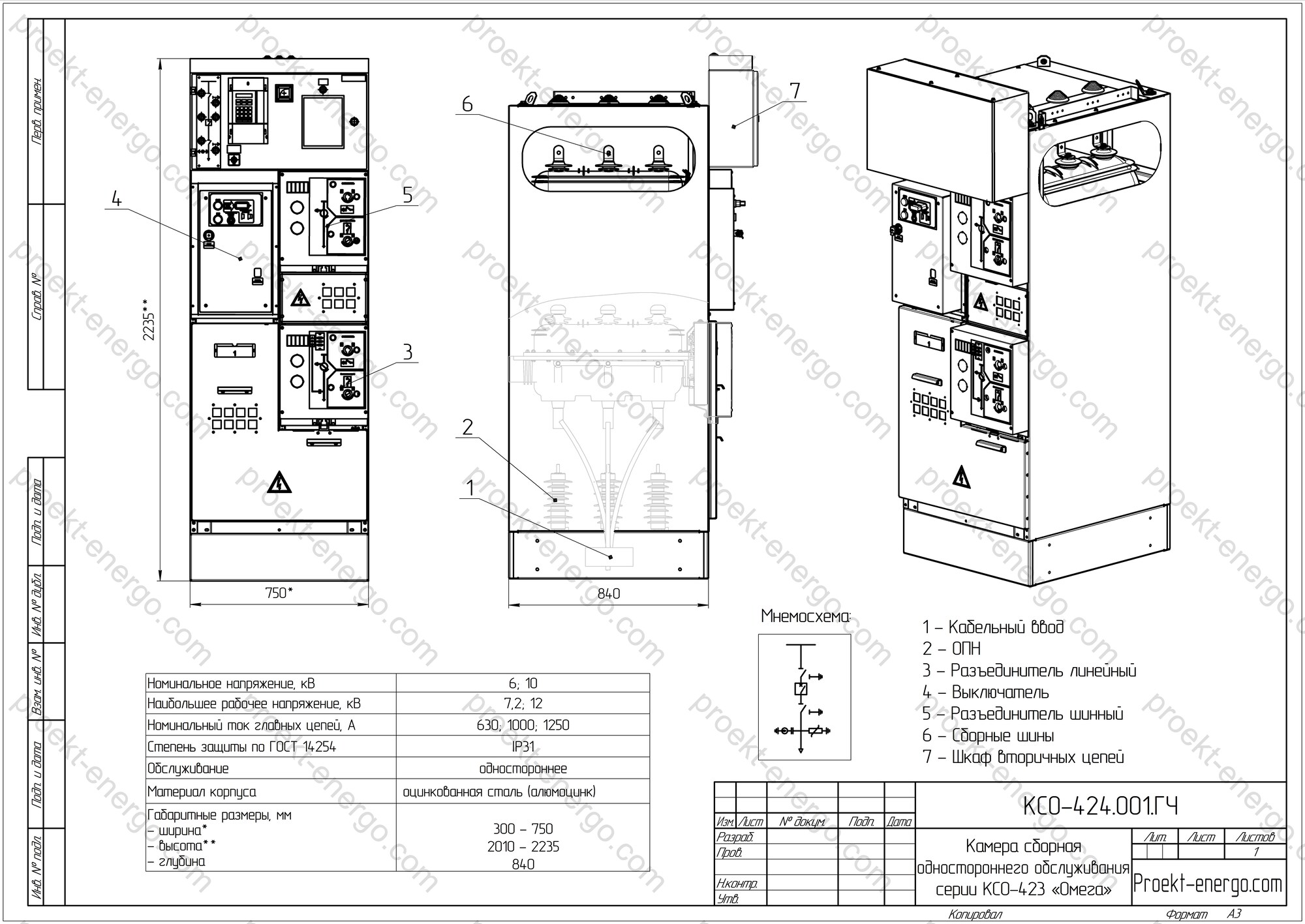
The “Omega” series uses three segregated compartments - busbar, apparatus, and cable - improving fault containment, serviceability, and safety. Compactness is achieved by arranging primary devices transverse to the main busbars, reducing depth without compromising dielectric performance. The busbar system is formed by consecutively joined copper bar segments on post insulators; provisions are made for through-bushings or bus partitions to enhance segregation and enable safe section coupling. For “two-row” halls, bus bridges or cable links between sections are available.

The apparatus compartment is withdrawable: the vacuum circuit-breaker, current transformers, and, where required, fuse blocks or combined modules are mounted on draw-out platforms. This accelerates inspection and replacement and allows maintenance with the door closed. The cable compartment is primarily arranged for bottom entry, with top entry available on request; supports and terminals are provided for temperature sensors at cable lugs, fixing of armoured cables, and provision for test plugs. The low-voltage compartment houses digital protection & control IEDs, AR/AR (ATS/AR), metering devices, terminal rows, RTU/telecontrol equipment, and auxiliary power; wiring is routed in an integrated cable duct with spare capacity for upgrades.

Enclosures are manufactured in two technological variants: a welded steel frame with powder coating (high rigidity and impact resistance) and a non-welded enclosure made of hot-dip coated steel (Z, ZA/AZ systems) to EN 10346 with bolted/riveted joints. The latter provides enhanced corrosion resistance and stable geometry in series production; coating type is selected to meet service-life and site corrosion requirements. Front doors use reinforced multi-point latching to improve resistance to arc-pressure surges and vibration.

A front-door mimic with LED indication shows device and circuit states. Built-in internal lighting (lamp holder and socket for a portable lamp with a front-mounted switch) enables routine work without de-energizing the switchgear; lamp replacement is safe and does not require removing voltage from primary or auxiliary circuits. A voltage-presence indication system (VDIS) with interface for portable detectors can be integrated into the interlocking logic as specified.

Safety and interlocking

KSO-423 “Omega” is engineered for operational safety. All circuit-breaker operations are performed with the door closed. A system of mechanical and electrical interlocks prevents hazardous actions: disconnector operation blocked with the breaker closed; earthing-switch closing blocked with the disconnector/breaker closed; racking blocked with the breaker closed; MV-compartment doors locked unless the earthing switch is closed. Trapped-key interlocking between panels/sections is available for procedures requiring coordinated actions.

Per IEC 62271-200, continuity categories LSC (e.g., LSC2A/LSC2B) and partition classes PM/PI are applied. When equipped with arc-handling measures (gas relief, reinforced hinges/latches, arc sensors), typical configurations can be type-tested for Internal Arc Classification (IAC), e.g., AFL/AFLR, providing personnel protection for the selected accessibility.

Versions and options

  • Main switching device. Medium-voltage vacuum circuit-breakers per IEC 62271-100 with interrupting ratings coordinated to calculated short-circuit levels and protection settings. Load-break switches and contactors (IEC 62271-106) can be used for special feeders; “circuit-breaker–fuse” combinations (IEC 62271-105) are available for specific applications.
  • Disconnectors and earthing switches. Devices per IEC 62271-102 with required mechanical/dynamic categories; bus-section disconnectors and bypass circuits can be provided for maintenance modes.
  • Protection, automation, and telecontrol. Digital IEDs for line/transformer/section protection, autoreclose/automatic transfer, and special schemes; integration via IEC 60870-5-104/IEC 61850, power-quality data export, and connection to local/upper-level SCADA.
  • Measurement and metering. CTs/VTs to the IEC 61869 series with required accuracy classes, commercial/technical metering, and power-quality panels.
  • Condition monitoring. Temperature sensors at cable lugs and busbars, arc-flash sensors, breaker operation counters, partial-discharge sensors - integrated into a predictive diagnostics system.
  • Enclosure & environment. Dual-layer powder coating or hot-dip Z/ZA/AZ coatings per EN 10346; seals, cable glands, and fire-stopping to the specified fire-safety class; seismic calculation/testing per the required category.
  • Cable infrastructure. Support for cables to IEC 60502-2 (6–30 kV) with termination kits and test provisions; bus bridges and cable links between sections.

Typical configurations

Based on standardized schemes, the following arrangements are typical: “incomer - section - feeder”, “dual incomers with ATS”, “incomer - transformer - feeder”, “incomer - section - section - feeders”, etc. For brownfield retrofits, transition panels and mechanical-interface compatibility are available. Depending on project needs, LSC categories up to LSC2B and PM (metal) or PI (insulating) partitions can be applied, allowing maintenance of an outgoing feeder without de-energizing adjacent feeders (within the selected category). Cable testing on feeder panels is supported via standard test plugs in the cable compartment.

Engaging contractors, switchgear manufacturers, and investors

We offer flexible cooperation models for localization and series production of KSO-423 “Omega”: supply of metal kits (enclosures, doors, draw-out trucks, busbar assemblies), licensing of shop documentation, outsourcing of harnesses and mounting panels, support of type/qualification tests (incl. internal-arc and functional safety), and staff training. For investors and manufacturing sites, a low-CAPEX production roadmap is available: adapting drawings to existing paint/galvanizing lines, fastener and hardware selection, routing sheets, quality plans (IQC/OQC), and incoming-inspection procedures for purchased items.

Documents

  • Tender package: single-line diagrams, equipment lists, data sheets, standards-compliance matrices, 3D visuals, and an explanatory note with effort estimate, delivery schedule, risk matrix, and mandatory test list.
  • Manufacturing (shop) documentation: enclosure and assembly drawings, BOMs, primary/secondary schematics, cable schedules, purchased-parts lists, routing sheets. Formats - DWG/DXF, STEP/Parasolid; models - for AutoCAD, SolidWorks, Inventor.
  • Interlocking logic and safety: inter-panel and intra-panel algorithms; condition tables for close/open/earth/rack-out/access; VDIS and arc-flash integration; safe-switching instructions for operators.
  • Commissioning & O&M: insulation-test programs, secondary-circuit checks, P&C settings, FAT/SAT protocols, maintenance regulations, torque charts, and lists of control measurements and diagnostic tests.

Compliance with standards

Design, manufacturing, and testing of KSO-423 “Omega” follow the requirements of the standards below (as applicable to the selected configuration and devices):

  1. IEC 62271-200 - AC metal-enclosed switchgear above 1 kV up to and including 52 kV (LSC categories, PM/PI partitions, internal-arc classification IAC).
  2. IEC 62271-1 - Common specifications for high-voltage switchgear and controlgear (consolidated edition).
  3. IEC 62271-100 - AC circuit-breakers for MV (2021 + Amd. 1:2024).
  4. IEC 62271-102 - Disconnectors and earthing switches (2018 + Amd. 1:2022).
  5. IEC 62271-105 - Combined “circuit-breaker–fuse” functional units.
  6. IEC 62271-106 - Contactors and motor-starters above 1 kV.
  7. IEC 61869-2 - Instrument transformers - Additional requirements for CTs.
  8. IEC 60038 - Standard voltages (2009 + Amd. 1:2021).
  9. EN/IEC 60721-3-3 - Environmental conditions for stationary use in weather-protected locations (replaces GOST 15150 U3 for climatic category); IEC 60529 - Degrees of protection (IP code).
  10. EN 10346 - Continuously hot-dip coated steel flat products (Z/ZA/AZ/AS/ZM) for corrosion-resistant enclosure versions.

Technical data

Rated voltage, kV 6; 10
Highest system voltage, kV 7.2; 12
Rated current of main circuits, A 630; 1250
Rated busbar current, A 630; 1250
Thermal short-time withstand current (3 s), kA 20
Peak withstand current (1 s), kA 51
Rated fuse current, A 200
Breaking capacity of 200 A fuses, kA 20
Environmental category (replaces GOST 15150 U3) EN/IEC 60721-3-3
Degree of protection IP31 (IEC 60529)
Overall dimensions, mm
- width
- depth
- height

300–750
840
2010–2235

We will prepare a complete engineering package - from the tender set to shop drawings and instructions for manufacturing, assembly, and commissioning. The documentation is adapted to your project requirements, preferred apparatus vendors, and plant capabilities. If you do not plan to fabricate parts and subassemblies in-house, we can arrange cooperation at partner facilities: enclosures, draw-out trucks, busbar systems, harnesses, and mounting panels. Final assembly, electrical installation, and testing are performed at your site with our technical support.

  • Pre-tender technical package: single-line diagrams, equipment lists, data sheets, standards-compliance matrices, 3D models/renders, and an explanatory note with effort, schedule, and risk assessment.
  • Shop drawings and 3-D models: enclosure and assembly drawings, primary/secondary schematics, BOMs, purchased-parts lists, cable schedules; formats - DWG, DXF, STEP, Parasolid; models - for AutoCAD, SolidWorks, Inventor.
  • Interlocking schemes and algorithms: inter-panel and intra-panel logic, trapped-key schemes, safe-operation sequences, signal/condition tables, integration of VDIS and arc-flash protection into the overall system.
  • Commissioning and operation: insulation-test programs, secondary-circuit verification, P&C IED settings, FAT/SAT protocols, maintenance regulations with task periodicities and control charts.

Benefits of working with us

You do not need to maintain a large engineering staff: our documentation set enables a mid-level engineer to start serial production without costly prototypes. We support the project end-to-end - from short-circuit studies and apparatus selection to IEC-compliant documentation, to staff training on safe switching and interlocks, crimping procedures, and torque charts.

For additional information on KSO-423 “Omega” please contact: inbox@proekt-energo.com

PDF - Download KSO-423 technical information

pdf

Proekt-Energo

FEEDBACK FORM

  • 3-D models

    3-D models

  • 3-D models

    3-D models

  • Operating manual for equipment

    Operating manual for equipment

  • Regulatory and technical documentation

    Regulatory and technical documentation

  • Regulatory and technical documentation

    Regulatory and technical documentation

  • Operating manual for equipment

    Operating manual for equipment

  • Regulatory and technical documentation

    Regulatory and technical documentation

  • 3-D models

    3-D models

  • Technical specifications

    Technical specifications

  • Equipment drawings

    Equipment drawings

  • Equipment drawings

    Equipment drawings

  • Operating manual for equipment

    Operating manual for equipment

  • Equipment drawings

    Equipment drawings

  • Technical specifications

    Technical specifications

  • Technical specifications

    Technical specifications